I’m using the internal 22k pullup on the input from the rotary encoder and also from the reed switch input, but I’ve noticed I appear to get false triggers on the reed switch input and more recently on the rotary encoder input.
I was using the internal 22k pullup, e.g.
pinMode(PUSH_BUTTON, INPUT_PULLUP);
But it now looks like this is too weak for real world usage.
I suppose I could solder on external pullups e.g. 4.7k or perhaps even 1k, to prevent false triggers, but it seems odd that STM would have 22k as the internal pullup, if its value was too high to be usable.
It could also be that a lot of the miss-triggers are caused by supply noise.
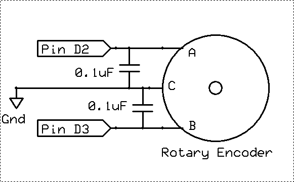
Note. I’m debouncing the rotary switch extrnally using 100nF cap across the switch, so I would have thought this would also act to decouple the pin and stop miss triggering as well as debouncing, but at the moment it doesnt seem to be working as well as I’d like ?
BTW. I’m powering the Maple Mini on Vin, via a 9V external supply, because the switched high current output – which drives a solenoid, is designed to run from 12V, but 9V seems to be plenty (but 5V is not quite enough)
Any thoughts about what I am doing wrong.
Ray
Ray
I agree it sounds like the input wires are too long, but I modified the code to disable the external reed switch detector, (which is on a 10ft long pair of wires), and its still going wrong, so I think its miss triggering on the rotary encoder, and the rotary encoder connections are only about 2 inches long, inside a box.
To be honest, I cut some corners, to save having to solder loads external components, I use the internall 22k pullups on all inputs, which are the 2 rotary encoder signals, as well as the push button that is on my rotary encoder, and also use the 22k pullups on the reed switch sensor.
To debounce, I just have a 100nF capacitors to gnd on all these inputs.
But initially I had a problem, where if I pushed the Press button on the rotary encoder, I”d get a miss trigger on the rotary encoder its self.
And to stop that happening, I had to change my wiring, so that it didnt have a common ground wire from the system GND to the button gnd and the rotary encoder ground.
I presumed the problem was that when the button was pushed, it shorts the 100nF to GND, (across the push button).
Somehow this was causing current to flow up the common GND, and caused the GND on the rotary encoder to rise, hence somehow applying noise / spike to the rotary encoder trigger input.
Basically, I’m doing the same as Nick Gammon describes here
http://www.gammon.com.au/forum/?id=11130
But the push button on the rotary encoder is debounced in the same way, and shares a common GND wire
I learnt something new.
For some reason I thought the internal pullups were 22k. But they are not !
On page 62 of the datasheet
http://www.st.com/content/ccc/resource/ … 161566.pdf
It says
RPU
Weak pull-up equivalent resistor min 30k, typical 40k, max 50k
Mine are appear to be around 42k.
So really I need a much lower external resistor, as these “weak” pullups are far to high to be usable in my application, (at least for the interrupt lines)
You may try to pass 3 turns (all wires incl gnd) via a ferrite bead with longer cables too.. when living close to a radio station
You may try to pass 3 turns (all wires incl gnd) via a ferrite bead with longer cables too.. when living close to a radio station
I started the same way on a cheap chinese rotary encoder i had, but when i noticed 1 step would trigger the interrupt over 50 times, i looked at the signal of my encoder with a logic analyzer, and there was about a 2ms gap between one line changing state, and then the other. So now i ended up just making a program that samples the pins every millisecond (and it does some debouncing by requiring the pin to have the new state on 2 consecutive reads), and it works very reliably, and it hardly taxes the processor at all, so unless your encoder can make lots of steps per second or is of far better quality than what i have, is using interrupts and all that effort in hardware debouncing really necessary?
(and in the end it’s running on a timer that also generates interrupts, i confess :p)
Btw, 100nF @3.3V, shorted down via 0.1ohm (esr+cont res) creates a 20ns long pulse of 30A current.. (mcu clock is 14ns).
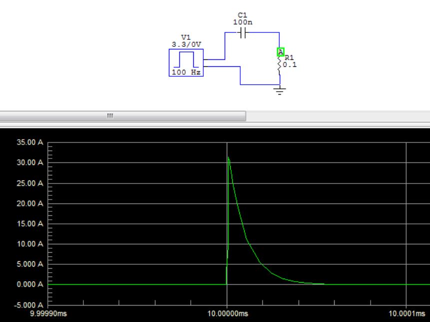
- Switch current 100nF.JPG (53.74 KiB) Viewed 553 times
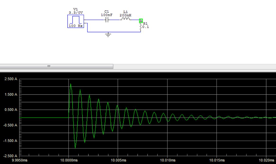
- Switch current 100nF 200nH 0_1ohm.JPG (81.29 KiB) Viewed 549 times
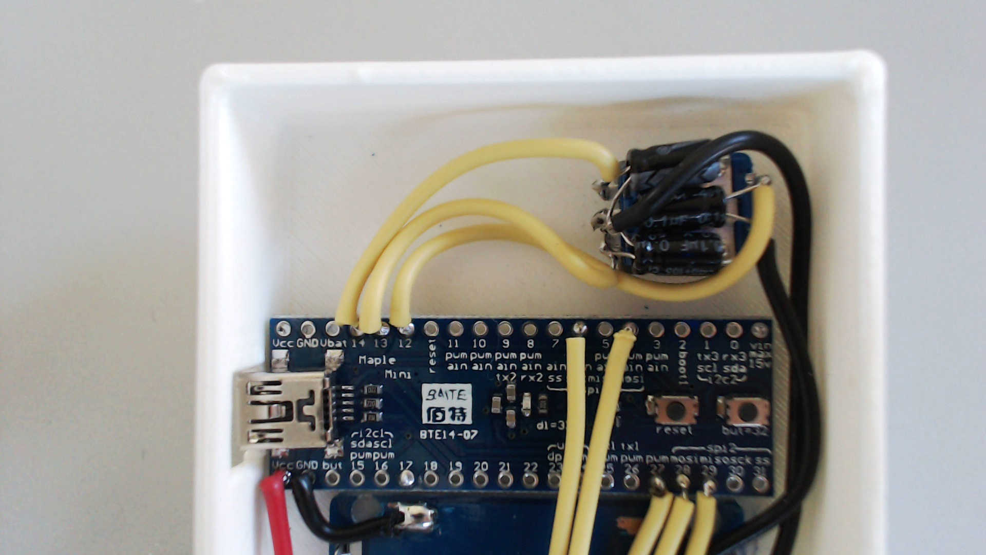
- Picture 21.jpg (110.52 KiB) Viewed 541 times
The rule-of-thumb for pull-up/pull-down is 10K. I doubt this would eliminate your issue.
– Poor input DC source over long length,
– Plastic enclosure
– FET + solenoid inductive load
I would minimize the voltage stability by use of a 1A DC-DC
Caps should be low ESR caps, tantalum preferred
Use ferrite filters between Maple and FET
You can probably live with the plastic box but do use ground strapping between common ground and the DC-DC The reference.
Ray
Solenoid this this one
http://www.ebay.com.au/itm/WS-2X-5-6lbs … 2245433151
Its supposed to be 12V but normally run it from 6V as it produces enough magnetism at 6V, however sometimes I need to use 9V.
FET is 2N7000 which is rated at 200mA continuous and 500mA when pulsed. And I’m only turning the FET on for 5mS and then off for 350mS.
The solenoid has a DC resistance of 50 Ohms, so at 9V the max current drawn should be inside the spec for the FET
Flyback diode is a 1n4148 – I could be blown, but I don’t have the unit exhibiting the problem (long story)
I have a partially built backup unit (the one I took a photo of) so I will need to add the solenoid and FET etc and attach my scope and see what’s going on !
But as the problem of miss triggering seems to be caused purely by pressing the push button on the rotary encoder and not purely by the FET and the solenoid, I think the main cause is just that the internal pullup’s are “weak” as described in STM’s on docs.
I won’t use the internal pullups again for any real world products which involve interrupt inputs, as it looks like the changes of miss triggering due to supply noise is too high.
I ended up running all the ‘commons’ through the base of an npn, and using just one line as the int. The base and collector lines were decoupled and I only had to deal with that one edge input.
Ok, it meant a scan at the int time to see what was active, but it certainly allowed me to tailor the circuit to my needs.
Possibly as high as 50k, and is probably only useful on inputs between devices on the same PCB.
I should have not tried to use the internal pullup for any external connections, as the lightlyhood of false triggering is too hig.
Basically, I’m doing the same as Nick Gammon describes here
http://www.gammon.com.au/forum/?id=11130
I do note however, that you are using 0.1uF electrolytics in your circuit. I would want to swap those out for some decent ceramics, and ground any metal areas on the encoder if they are isolated. Just my preference though
I do note however, that you are using 0.1uF electrolytics in your circuit. I would want to swap those out for some decent ceramics, and ground any metal areas on the encoder if they are isolated. Just my preference though
//stm32f103cb 20k ram 128k flash
#define B_nextfile PA4
void setup()
{
afio_cfg_debug_ports(AFIO_DEBUG_SW_ONLY); // release PB3 and PB5
afio_remap(AFIO_REMAP_SPI1); // remap SPI1
gpio_set_mode(GPIOB, 3, GPIO_AF_OUTPUT_PP);
gpio_set_mode(GPIOB, 4, GPIO_INPUT_FLOATING);
gpio_set_mode(GPIOB, 5, GPIO_AF_OUTPUT_PP);
Serial.begin(250000);delay(1000);
Serial.println("serial ok");
pinMode(B_nextfile,INPUT_PULLUP) ;
attachInterrupt(B_nextfile,isr_next,FALLING);
}
int f1;
void loop()
{
Serial.println(f1);
delay(10000);
}
void isr_next(void)
{
++f1;
}
The spec says their values can range from 30k to 50k
Use a suitable value external pullup
[octavio – Sun Sep 17, 2017 11:33 pm] –
The pullups values are similar to those found in other microcontrollers (atmega,xmega) and they work without problem in those microcontrollers,with or without filters if the wires are not too large.And 50k seems a suitable value,sometimes i have used 1M external resistors to reduce current consumption and still works.
This is irrelevant. They are not a STM processor.
Second, it does not seem to be a bug for me, it is rather the MCU which runs couple of times faster than the AVR processors.
Third, you should put a resistor (100 Ohm) in series with the capacitor to the button in order to reduce the currents produced by shorting the capacitor when you press the button. Otherwise it can generate noise spikes which can erroneously trigger interrupts.
volatile int f1;[Pito – Mon Sep 18, 2017 6:38 pm] –
Btw, I am running here (BPill) 3 attached interrupts at 3 pins, the first fires 1300x per second, the second about 550x, the third about 4-10x per second (all at random times). I am not loosing a single one (so far). In parallel Serial.print(), math, HardWire I2C, bitbanged SPI into Xilinx.
Doing in ISR exactly what you do – incrementing a volatile uint32_t.
Can you post what circuit and settings you are using for debugging if any? (internal pullup, internall pulldown, floating with external resistor of XXohms to 3v3, etc)
That will help a lot as starting point to other people since you are getting good results.
There are 360ohm resistors in series in my case. I’ve put them there to minimize ringing (it may catch more interrupts when it rings). Why it may ring? Because the CMOS outputs are fast and the wires are long, the parasitic LC driven by fast edges rings. The same may happen with encoders, switches etc.
The resistor’s value could be higher, as the interrupt’s frequency is rather low (max few kilohertz) – thus the RC will not mess too much.
CMOS ---> 360ohm -----> BPill interrupt input
About volatile: the value is not written out of the ISR and is read on with a single instruction ,so it should not be a problem.
Could you explain me in more detail – what does it mean you get interrupts “without pin changing value” when you also add the input goes “slowly” from zero to 3.3V. Can you clarify it more precisely pls?
If your signal goes slow from 0 to 3.3V in 200ms, you may get 50 additional interrupts. That is because your signal is slow.
The decision level for 1 or 0 in 3.3V CMOS is at 1.65V approximately.
The decision level may change, as the environment is noisy. So you have to spend a minimal time in that region. The logic while at 1.65V will trigger each time the level changes by few millivolts (the changes comes from VCC and GND – it jumps +/- 30mV).
Therefore Schmitt triggers are used – the Schmitt trigger introduces hysteresis – thus a small change at the 1.65V decision level will not retrigger. The BluePill does not have Schmitt triggers at its inputs I think (or does it)? It does have the Schmitt trigger inputs.
https://en.wikipedia.org/wiki/Schmitt_trigger
When somebody wants to chase each and every edge:
1. you must use fast edges (to minimize time spent at 1.65V)
2. or you have to use Schmitt triggers to process slow signals (where the edges are slow)
PS: The Schmitt trigger’s hysteresis in BPill is 200mV (datasheet). Hopefully it works. So – when your slow growing signal does not change (while around 1.65V) by 200mV downhill, you have to get 1 interrupt. Anyway, I would recommend to have edges fast.
PA4 is SPI1 NSS, you do a remapping of SPI1, maybe there is something weird.
BTW, SPI1 is not at PB3,4,5 by default, but on PA4,5,6,7.
Steve is correct.. If you dont put a resistor in series with the switch, the surge current to charge the capacitor will cause problems. I experienced this when using a rotary encoder.
@pito.. +1
Supply rail on the BluePill seems quite noisy when I look at it with a scope, and this will potentially cause multiple triggers,
E.g if the i put voltage is from a cap that is slowly charging up, its effectively a high pass filter, and will be a fairly smooth rise.
where as the GPIO input threshold changes all the time as its approx Vcc/2 and Vcc varies slightly all the time.
Most probably he has the switch from pin against GND, pullup, and the 10uF capacitor from pin to GND. So he discharges the capacitor to GND, and then he slowly charges it via pullup. So the voltage rises kRC. He is using falling edge, so he fires the interrupt when he presses the button against ground.
BTW. good call about potential issues with NSS.
Code was added to make it usable as GPIO even when using SPI, and I dont recall anyone having problems with using it as an output.
But there may be problems as an input or with using it as an interrupt pin

