I would like to have an way to turn it on and off without using a simple power switch. My thoughts are to use an N gate MOSFET with a push button in parallel as shown below. Simply put, from an OFF state, GRD is connected to the MCU initially by pressing the push button (which will have to be held down for a couple of seconds) and when the MCU has booted up, it asserts the digital pin connected to the latch keeping GRD connected via the MOSFET. The unit is turned off, either after a period of inactivity to save power or after a seperate ‘OFF’ button has been pressed, or ‘OFF’ has been selected on the menu and the MCU has put its afairs in order (eg saving config data so it starts up next time in the same place) prior to unasserting the latch.
I would appreciate some input. Does this sound like a feasable solution?
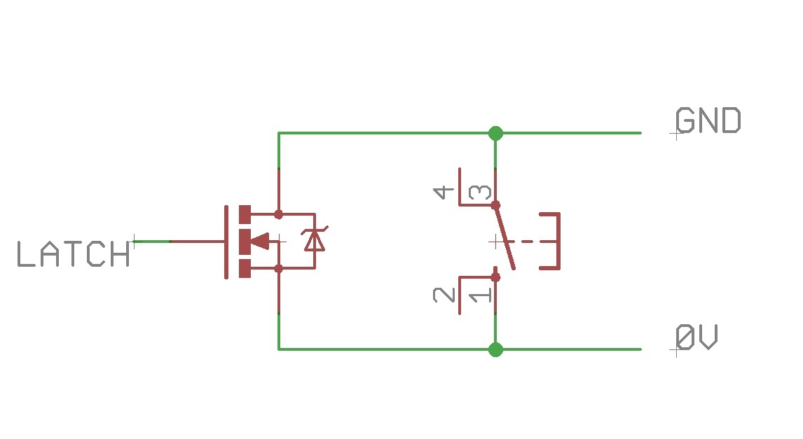
- on_switch.jpg (38.67 KiB) Viewed 789 times
I added a small foil capacitor between Gate and ground, while the Gate-Vcc was 2 small metallic blobs on the (plastic) case. The multimeter was powered via that mosfet.
While putting my finger on the blobs it charged the capacitor immediately (via finger’s R), the mosfet switched on, after about 10minutes the C discharged itself and the multimeter switched off.
I liked it, my first invention
https://www.youtube.com/watch?v=VRQ3XJO1VFo
+Ekawahyu Susilo Yup, touch control is implemented in software using pure GPIO functionality. In short – you set GPIO to output low, then start the timer and switch GPIO to input with pull-up (internal or external). Due to pad (and human body) capacitance, the GPIO input level will get high not instantly(it will charge the capacitance for some time, no more than dozen cpu ticks), this period is measured with the timer and compared to a threshold. Most of hardware touch controllers work just in the same way.
@Pito, that’s an excellent method, well done, I wish I was that knowledgeable. I think I’ll stick to a tactile switch though.
I therefore need some protection to stop the board destroying magic smoke from appearing.
My prototype board has a 2 X 20 pin connector so I can plug a blue pill in and also has a 5V regulator and a 3.3V regulator to supply both 5V and 3.3V to the blue pill, the TFT and the sensors. It also has a coin cell for the RTC. Can anyone help with suggesting what I need to ensure that when I plug the USB in to the blue pill, I keep it and the battery power seperate to ensure no magic smoke ensues?
Thanks, Steve.
More specifically, you probably need a Schottky diode in line with one or both power inputs to stop you from feeding one supply with the voltage of the other. Simple rectifier diodes may work, but may have too much voltage drop. Things become more complicated if your batteries are rechargeable, even more so if they are LiPo so perhaps we need a slightly more complex solution than the one I have just suggested.
https://circuits.io/circuits/3352039-so … h-5v-logic
Center button is ON. You can also check its pressed state with the MCU at the rightmost voltmeter’s positive input. It will be high when you press button.
The other button is OFF. You can change it to an MCU pin, so you can turn off power from software.
http://playground.arduino.cc/Main/Capac … n.CapSense
https://www.youtube.com/watch?v=BHQPqQ_5ulc
Ive been thinking and I stand to be corrected if any of my thoughts are wrong.
The blue pill does not need 5V to run but when the USB is plugged in, the 5V pin is high so I can take that to a LiPo charger. The LiPo voltage will run my TFT shield when applied to the 5V pin as I have tested it but the backlight may not be full brightness however, it does seem well lit. It will also power the accelerometers, again I have checked. So basically, I only need to worry about the 3.3V side which I am protecting with a Schottky diode.
The following is my design for the power supply with a charger, 3.3V regulator and an ‘on’ button which is latched once the blue pill is booted up. I also have a PTC fuse to protect the LiPo circuit and maybe I should have included a second diode to protect from connecting the LiPo the wrong way round
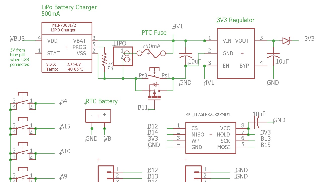
- charger.jpg (155.11 KiB) Viewed 693 times
i think it also has ‘wake on interrupt’ features where in you can make a button connected to a gpio pin to wake the mcu up from sleep
you could literally program a timer in software in the stm32f103 to ‘switch off’ (rather set ‘sleep’ or ‘stand by’ modes) after a timeout and you could reset that timer on any activity (in software)
My project is an extension of the board I already have – see below
Steve.
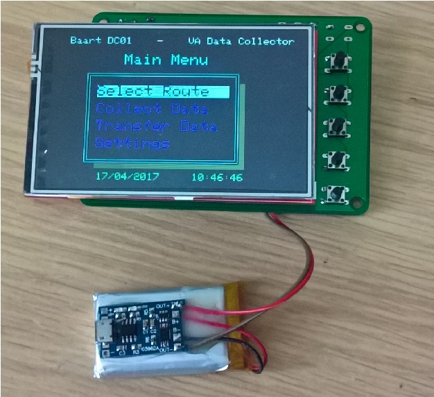
- WP_20170417_10_46_28_Pro.jpg (184.87 KiB) Viewed 207 times
