I bought this card from aliexpress:
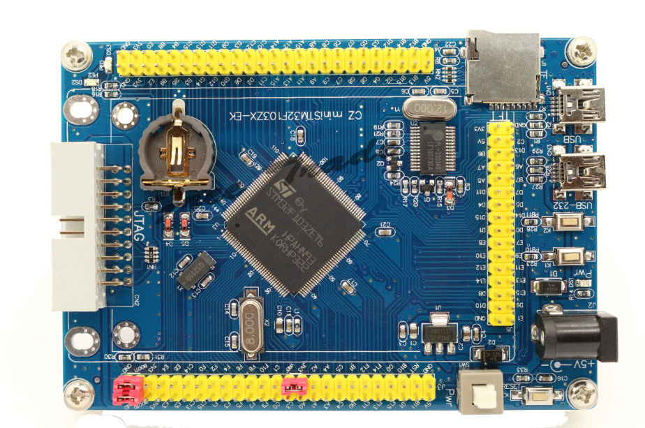
- UT8_2CzXipaXXagOFbXY.jpg (232.48 KiB) Viewed 4359 times
It you don’t have ST-Link, you can use that USB-232 port to upload bins to the board.
If you connect the jumper from boot0 to +3.3 and from boot1 to GND, the board will boot the STM ROM bootloader, which uses USART 1.
As that is connected to the USB-232 with the converter, you can now use a program in Windows to upload .bin files to the board.
The STM tool for that is called something like Bootloader Demonstrator. Search for it online, it’s on STM webpage somewhere. It is a Windows only tool as far as I know.
At that point, unless you need to use all the flash in the board (unlikely), I would upload the new bootloader that we have modified to work on generic boards. It’s in a repo in Roger’s github, and there is a link to it in the announcements forum section. (the repo is STM32duino-bootloader).
Your board seems to have 2 leds in PE2 and PE0, and Roger has compiled the bootloader for several different led ports, but I don’t see it for PE2 or PE0, so you will need to modify the source and compile it.
When I get to work I can try to download the source and modify it for you if you have problems doing that.
Once you upload the STM32duino bootloader, you can use the main port to upload sketches with the DFU bootloader, which is easier to use because it reboots the board automatically and goes in bootloader mode a few seconds on every reboot before jumping to the sketch, so you don’t need to be changing the boot0 jumper all the time.
I am at work right now so I dont have any board to test it out.
I set the led to port PE2, and the button to GPIOB11, which seems to be one of the buttons in the front of that board next to the USB connectors.
Tonight I control the LEDs on my card but the picture seems to me to read and PE0 PE2 and the electrical diagram provided by the Chinese seller confirms it but I want to spend a few minutes to check the accuracy.
For programming I have a USB-232 working at 3.3v but Thursday I should deliver an original ST-Link V2 bought on Ebay.
I work on Linux so I need software that run on it. I was able to program the ST Nucleo Boards in linux ( on Eclipse) by filling out a simple project in GitHub (https://github.com/texane/stlink) .
I see now that while I was writing this mail have already taken steps to compile the bootloader ![]() Thanks.
Thanks.
I think I need to read something on the bootloader to understand how it works, how to it write and how to use it to load firmware.
As always, a step at a time
I keep you updated
Thanks
Drk
https://code.google.com/p/stm32flash/
I have not used it ever, so dont know if it works, but you can give it a shot and let us know.
Once you upload the bootloader to the board, it will work like the bootloader in the official Maple and Maple Mini boards, with the DFU protocol.
This is what is called by the following upload methods in linux.
nucleo_f103rb.upload.tool=stlink_upload

genericSTM32F103C.menu.upload_method.STLinkMethod.upload.tool=stlink_upload

genericSTM32F103R.menu.upload_method.STLinkMethod.upload.tool=stlink_upload

genericSTM32F103V.menu.upload_method.STLinkMethod.upload.tool=stlink_upload

genericSTM32F103Z.menu.upload_method.STLinkMethod.upload.tool=stlink_upload
I spent a bit of time to understand how it is made this card. I found this:
Led –> PE0, PE2
Button –> PB10, PB11
One of the two USB port is interfaced to Chip PL2303HX. There are also two transistor which was discussed on the forum.
BOOT1 ( PB2 )
RESET# ( NRST = pin25 )
PL2303_TXD —> USART1_RX ( PA10 )
PL2303_RXD <— USART1_TX ( PA9 )
Linux reads me ttyUSB0 and serial device when I connect the board to the computer.
The second USB port is connected to pins USB_DM ( PA11 ) and USB_DP ( PA12 )
Bootloader and Programmer
Since I have a programmer ST-Link v2 do not think I can be useful a bootloader, I can directly use the programmer using the JTAG connector.
If I understand it to be able to program the STM32 chip via external programmer I needed to connect the pin BOOT1 to Ground?
Can you confirm this?
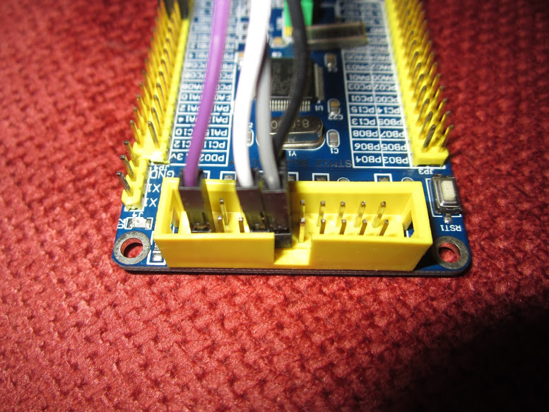
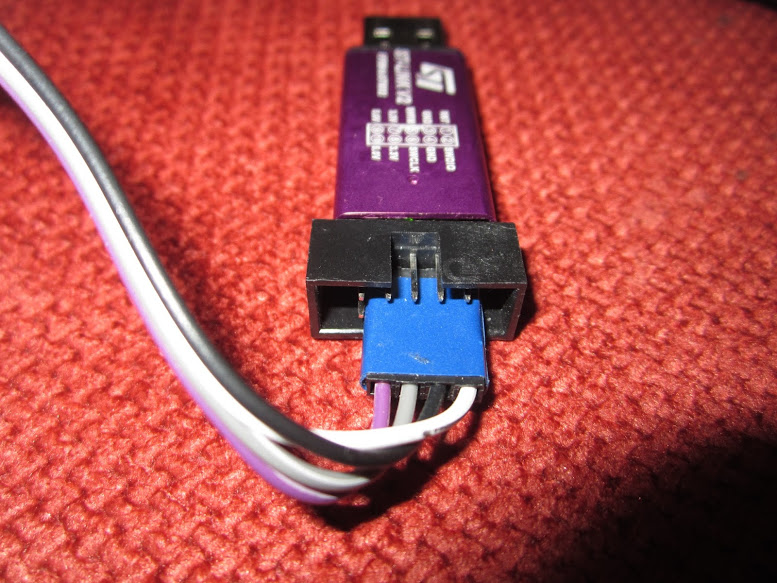
The controller ST-Link v2 has two connectors: one JTAG and a 4-pin connector.
The JTAG is simple because the generic card STM32 I own has a dedicated JTAG connector, but for the 4 Pin how do I connect to the Board?
Drk
The JTAG is simple because the generic card STM32 I own has a dedicated JTAG connector, but for the 4 Pin how do I connect to the Board?
Since I have a programmer ST-Link v2 do not think I can be useful a bootloader, I can directly use the programmer using the JTAG connector.
If I understand it to be able to program the STM32 chip via external programmer I needed to connect the pin BOOT1 to Ground?
Can you confirm this?
In the WE finally I put my hands on the controller ST-Link V2 delivered by the postman.
As a first test I used the classic Blik sckech. I only had to change the LED pin ( PE2 )
Board (CZ Mini STM32F103) and programmer, they were connected through the JTAG port.
BOOT0 and BOOT1 set on the ground.
I Compiled and binary Flashing directly from Arduino IDE.
Everything worked in the first test. No problems found. The skech works perfectly !!!!!
There was no need to change Jumper for BOOT0 and BOOT1.
As a first test I chose not to install the Bootloader
I’m really happy and super excited. Now I have to go deeper with the study.
Thank you all for your support.
Drk
The Bootloader is worth installing, however I’ve not specifically compiled a version for a board with the LED on PE2
Annoyingly there is no standardisation for which LED these boards use.
I will try to create make file target / config for a generic board with LED on PE2
I’ve just created a bootloader version for that board (so it flashes the correct LED).
https://github.com/rogerclarkmelbourne/ … 20_pe2.bin
When you feel like installing the bootloader let me know how you get on.
BTW. On windows you need to install a driver (see driver/win/install.bat ) On Linux there is a script you need to run (install.sh)
On Mac no other installation should be required.
See https://www.youtube.com/watch?v=0jdJp3TQuJY
Note, If it doesnt look like the bootloader is working, I could have screwed up the config, as I don’t have a board to test it on (but I can have a go testing on another one of my boards by attaching an external LED)
Cheers
Roger


All Comments