I know a lot of you use the TP4055 based single cell Lipo charger / discharge protection modules, but I’m wondering if anyone has actually checked their low voltage cutoff point ?
I’ve been doing some tests, and they do not seem to disconnect the battery to prevent over discharge of the Lipo cell.
I’ve tried 2 of these module and both of them seem to behave the same.
When I first connect the battery, if the battery voltage is not high enough, they module does not seem to connect the battery to the output terminals, until I supply it with 5V from USB.
However once have primed it with 5V, I can immediately remove the 5V input and the module seems to keep supplying current until the battery down as low as 2.5V
Has anyone actually checked that these modules do what they claim ?
Update..
I’ve just done some more testing, and these modules behave quite strangely
If I connect my bench PSU as the battery, and slowly increase the voltage, there is no output until the “battery” gets to around 2V.
As I increase the “battery” voltage to 4.2V, I noticed that the output voltage is significantly lower than the “battery” voltage.
However, if I briefly attach another power source (I used a battery) to the input of the module, the output voltage jumped to virtually the voltage
If I then lower the “battery” voltage (from my PSU), the output voltage tracks the battery voltage until the battery gets down to 2.4V, at which point the output of the module cuts off.
Hence it appears that the lower cut off point is 2.4V, which seems far to low for a normal LiPo cell, as I thought the minimum voltage for a single LiPo cell was around 3V
BTW. This was with no load. But in my practical tests, with 75mA load, these modules appeared to do the same thing
FYI
The modules that I have, use a
TP4055 (Lipo charger IC) https://dlnmh9ip6v2uc.cloudfront.net/da … TP4056.pdf
S8205 BATTERY PROTECTION IC FOR 4-SERIES OR 5-SERIES CELL PACK https://www.ablic.com/en/doc/datasheet/ … 5A_B_E.pdf
DW01A “One Cell Lithium-ion/Polymer Battery Protection IC” http://escooter.org.ua/_fr/1/DW01A-DS-10_EN.pdf
I’m not sure why it using the S8205 as well as the DW01A, and that the S8205 is intended for use with a 4 or 5 cell pack, not a single cell that this module is designed to connect to.
What I find interesting about both these devices, is that their “over discharge protection voltage” matches what I observed with these modules, as its around 2.35V
But as far as I can tell, its best not to discharge LiPo cells below 3V, and a lot of sources specify a minimum voltage of 3.2V or even higher.
Perhaps someone can explain why these devices have such low voltages for the over discharge protection.
It’s nice to know that should the regulator still draws current below the drop out point this will prevent the Li-po from going to zero.
[Riva – Fri Oct 12, 2018 8:04 am] –
Interesting but does it really matter that much if your using an LDO regulator to drop the voltage to 3.3V as this will stop working around 3.4V to 3.5V anyway and prevent further voltage drop?
It’s nice to know that should the regulator still draws current below the drop out point this will prevent the Li-po from going to zero.
I’m not sure what happens to a LDO if the voltage drops below 3.3V. My experience with other regulators is that if the supply voltage goes below the regulated output voltage, that the LDO just outputs whatever it receives, minus a small voltage drop.
I have some devices nRF51 and nRF52 which will work fine right down to around 1.8V, so in that case the discharge protection would kick in before the MCU stopped
But in the case of the board I was using the battery charger module with has a buck EA3036 buck converter as the regulator, and that has a minimum input voltage of 2.7V according to the datasheet.I’m not sure if it continues to output 3.3V even if its input is 2.7V i.e whether its a boost converter or not.
I guess the most surprising thing was that the cutoff voltage on these discharge protection IC’s is as low as 2.4V
to cut to the chase see a little bit at 0:40 and the new selected IC at 8:30 https://www.youtube.com/watch?v=Fj0XuYiE7HU&t=8s
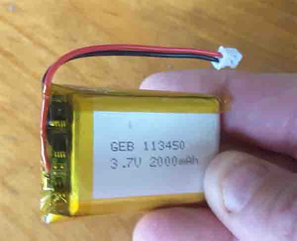
- battery.jpg (27.28 KiB) Viewed 407 times
[flyboy74 – Fri Oct 12, 2018 10:46 pm] –
I also usually use batteries that has manufacture builtin protection on the battery
battery.jpg
Thats interesting, I didnt know you can get them with built in protection, in a small package
I mainly used recycled batteries, as the local library has a battery recycling bin, and I’ve managed to salvage several laptop, and cordless drill battery packs, which are a great source of free cells.
At 2000Mah in a little square shaped package like that it is way more capacity than I need for any of my little MCU projects and fits very easy on to the project.
The only problem that I have had is there isn’t a polarity for wiring the connector and have plugged in batteries backwards and smoked up a project so now am super careful on checking before plugging now ![]()
[RogerClark – Fri Oct 12, 2018 12:07 pm] –
I’m not sure what happens to a LDO if the voltage drops below 3.3V. My experience with other regulators is that if the supply voltage goes below the regulated output voltage, that the LDO just outputs whatever it receives, minus a small voltage drop.
That’s ideal for me with my ESP8266 devices as I don’t need to use an external voltage divider to check battery level. Just use ESP.getVcc() and flag when voltage starts to drop below about 3.2V and I know the Lipo needs replacing.
I’m trying to determine the best MCU for low power operation but it takes months to discharge a 18650 and even resorting to a small 600mAh battery it takes over 30 days with a atmega32u4 taking 6 BME280 readings per hour and sending averaged readings twice per hour using Lora.
It’s difficuot to know how long batteries will last.
I bought a board from Nordic Semiconductor which does precise low current measurements, and is intended for profiling how long their chips will run from a battery, but it will measure any low current load.
( I am not sure if it would measure an ESP32 as they can take more current )
The big unknown seems to be how much charge the battery will loose on its own, even without a load.
lipo cells seem to hold their charge quite well, but they are not perfect.
Hence the calculation to determine how long a battery will last, has a lot of uncertainty and the only way to know for sure, is to actually test it
It seems during deep sleep most of the other components on the board will draw much more power than the MCU in deep sleep. The quiescent current of many of the components is much higher than the UPL of the MCU. Some big users are LDOs and voltage dividers on the battery monitor. I did have a link on a tiny little IC that is a boost/buck converter from TI that is a super efficient and has a number of modes : buck converter when battery is above 3.4v then it by-passes the switching part and shuts it down till the battery drops below 3.1v then it starts up as a boost converter to step it up to 3.3v, it also has a mode where it detects that there is very low current because of MCU in deep sleep and changes the freq of the boost/buck converter to be more efficient at that current. I also saw a design of voltage divider where a GPIO pin need to push open a mosfet to turn on the voltage divider that way it isn’t draining current when your not using it.
Also on another note how you leave the MCU before deep sleep has a big change on current draw. If pins are left set as outputs before entering deep sleep those pins will allow current to drain away.
[flyboy74 – Sat Oct 13, 2018 9:14 pm] –
Also on another note how you leave the MCU before deep sleep has a big change on current draw. If pins are left set as outputs before entering deep sleep those pins will allow current to drain away.
Yes, to reduce battery drain during sleep I stop SPI & I2C and turn off internal pull up resistors.
I have been toying with the idea of TPL5110 and/or TPL5111 nano timers to try and save a few extra nA’s but I will see how long my current batteries last first and this will probably be about 6 months from now.
A bit late on the band wagon for them but I have started to investigate the nRF51822 chips but it would be a steep learning curve to figure out the code so this will probably be a dead end.


