USB To SPI I2C IIC Serial Port Adapter
https://www.aliexpress.com/item/USB-To- … 5ce3eb61b6
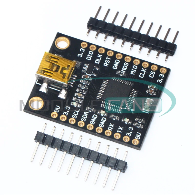
Looks like its pre-flashed with firmware so that it can be used as a USB to SPI etc
But the description also says
This Module can use for STM32F103C8T6 minimum system Development board If can be Programming,But we don’t provide Technical Support,Please Know it.
However it would probably need to be flashed via Serial and its hard to know whether the Boot0 pin is available .
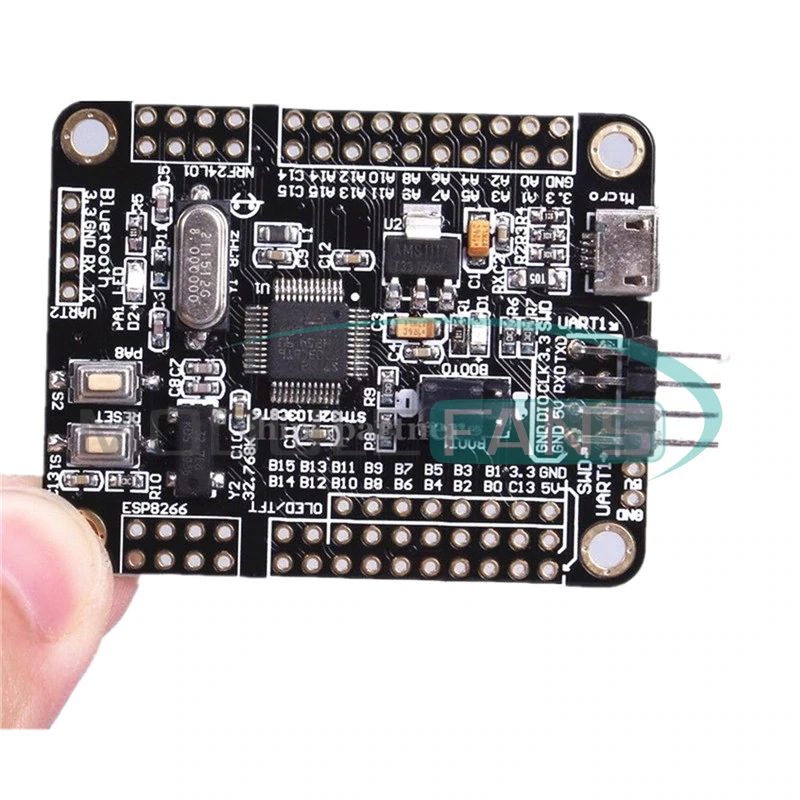
this board unfortunately doesn’t have the square indicating pin 1 on either the nrf or the esp connector track ends.
oh and the oled/tft pining isn’t labeled either, but it does have unpopulated eprom, spi flash and sd card track / pads
srp
this board unfortunately doesn’t have the square indicating pin 1 on either the nrf or the esp connector track ends.
oh and the oled/tft pining isn’t labeled either, but it does have unpopulated eprom, spi flash and sd card track / pads
srp
USB To SPI I2C IIC Serial Port Adapter
…
Looks like its pre-flashed with firmware so that it can be used as a USB to SPI etc
…
I think the board operates as different devices depending on what pins you pull high or low, and is set at boot time.
I doubt its possible to get the source code, unless they are just flashing with some open source firmware for the STM32.
They are charging several dollars premium for the firmware, as the board is less functional than the Blue Pill, but costs about 3 times as much.
I guess it would be interesting to know how the SPI driver works on the PC, but I suspect it may enumerate as Serial for all functions.
It may even use Serial for I2C where the address would need to be sent before each byte of data
Controlling SPI CS etc is also an interesting point, I guess that would be done by setting DTR etc
[RogerClark – Fri Dec 30, 2016 10:00 am] –
I noticed this board on AliExpressUSB To SPI I2C IIC Serial Port Adapter
https://www.aliexpress.com/item/USB-To- … 5ce3eb61b6
Looks like its pre-flashed with firmware so that it can be used as a USB to SPI etc
But the description also says
This Module can use for STM32F103C8T6 minimum system Development board If can be Programming,But we don’t provide Technical Support,Please Know it.
However it would probably need to be flashed via Serial and its hard to know whether the Boot0 pin is available .
Hi,
I am new to STM32 altogether and I am the sucker who bought this board. This board switches between USB to I2C, USB to Serial or USB to SPI by grounding either MOSI, RXD or SDA pins and I have no idea how the I2C or SPI work, I tried all sorts of methods sending data via the USB virtual comport in I2C or SPI mode but nothing seem to work. I have attached a complete dump of the firmware from the chip. I hope I am doing it right. It is done using ST-Link and I save the entire flash memory.
If you can help see how this thing works, it will be much appreciated.
When the usb is connected to PC, it shows up as a CH340 Virtual comm port in all 3 modes.
DId you look in the Windows device manager to see what devices appear when you connect it with the relevant pins pulled high or low?
Edit
Flashed the code to a BluePill but the USB device comes up as unknown, and looking in the device manager, this is because the USB is not functioning correctly.
There should be value in the windows device manager for Hardware ID’s, but it just appears as “USB Unknown”
Do you know what clock crystal is on that board ?
Also when you backed-up the whole flash, there seems to be less code than I’d expect,
[RogerClark – Sat Sep 16, 2017 9:27 pm] –
Are you trying to use it as USB to Serial, or USB to SPI etc ?DId you look in the Windows device manager to see what devices appear when you connect it with the relevant pins pulled high or low?
Edit
Flashed the code to a BluePill but the USB device comes up as unknown, and looking in the device manager, this is because the USB is not functioning correctly.
There should be value in the windows device manager for Hardware ID’s, but it just appears as “USB Unknown”
Do you know what clock crystal is on that board ?
Also when you backed-up the whole flash, there seems to be less code than I’d expect,
Yes, I am trying to use it as USB to Serial, USB to SPI and USB to I2C, I have successfully use it as USB to Serial but I can’t figure out how to use it as USB to I2C and USB to SPI.
To switch the mode to USB to I2C, you need to ground the RX pin.
To swtich the mode to USB to SPI, you need to ground the SDA pin.
To switch the mode to USB to Serial, you need to ground the MOSI pin.
The reason why you are getting an unknown USB device is because you need to choose one of the 3 modes above, meaning you must gound one of the pins before plugging it into the computer. Once you ground one of the pins, either RX, SDA or MOSI, it will come up as a CH340 Virtual comm port for all 3 types. I am not sure what the associated RX,SDA and MOSI pins are, but most probably will be hardware serial, I2C and SPI?
Edit : I went through the traces, I suspect I2C is on I2C1, SPI is on SPI1 and UART is on UART2. There are also 3 LED indicators which will indicate what mode the board is in, the pins the LEDs are connect to I am not sure, can’t see the traces.
Erm, as for the backed up, do I need to do anything on the ST-Link utility? I simply dump the device memory, I don’t think it will save zero values in the file, will they, meaning it will yield 64K since it is a stm32F103C8T6 (64k) device?
As for the crystal on the board, I am not sure of smd codes, but I have enclosed a enlarged photo of what I think is the crystal. The rest looks like resistors and caps and I think one is a LDO regulator probably the 1117.
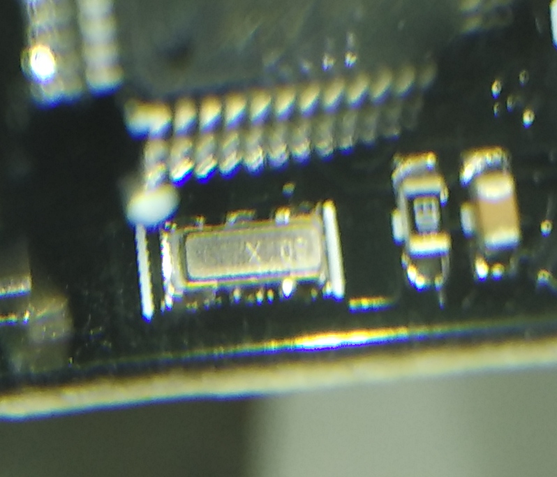
- IMG_20170918_130840_BURST1_cr.jpg (181.99 KiB) Viewed 1093 times
( ground the pin prior to plugging in the USB)
I’ll need to double check my board is not faulty, but at the moment it looks like the hex file you sent may be incomplete
I noticed 2 other people had downloaded it, but no one else has commented about whether it worked for them
Re: Crystal
Looks like its 8Mhz like the BluePill and most other F103 boards
BTW.
One other reason it may not work on the BluePill is often to stop people running the code on a different board, the code checks for another combination of pins always being pulled high or low or potentially a specific voltage on one of the ADC pins
But usually they also read-protect the code if they are concerned about it being re-used
I tried a different way of dumping the firmware. I used openocd and then via reset halt (I think these is the entry point. xPSR: 0x01000000 pc: 0x0800125c msp: 0x20001700) i did an image dump from 0x08000000 size 0x1ffff which yielded 128K dump image. Please see the attached.
- usbfirmware.zip
- 128k bin dump
- (14.14 KiB) Downloaded 19 times
I will double check the BluePill I was testing with, does not have a hardware fault ( as they are prone to bad connections on the USB connector)
Then I will try your latest code dump
Thanks…
BTW.
I had a quick look on TaoBao to see if I could find the board listed, as sometimes they post more information to TaoBao than to eBay or AliExpress, but I could not find it, even then I translated the description to chinese using google translate.
There must be more information on this adaptor somewhere, e.g some sort of commands documentation, because I don’t see how it could be useable for I2C otherwise..
I can just about understand how it could do Serial to SPI as long as it didnt have to use Chip Select, just by passing bytes to and from SPI to USB.
But some SPI devices require CS for synchronisation and framing.
I have tried almost all the software for similar adapters but none of them work.
Currently the board is in I2c mode and connected to a PCA9685. When I used arduino ide serial monitor, it is throwing scanning for device messages and displsying the i2c addtess of the 9685. However, when i key in anything to the serial, the messages will stop and the device will no longer respond.
I
The only difference would be that you’d need to use a different USB driver as we don’t have code that emulates the same USB to Serial adaptor.
But apart from that, I would have thought that writing code to transfer from USB Serial to I2C would not be too hard to write
Anyway for the usb to i2c/spi/uart, there is already an opensource firmware littlewire that works on attiny digispark that cost $1.0
[flodejr – Tue Sep 19, 2017 1:12 am] –
Yah worse case, i will just flash it into a bmp. Just that i paid premiun for the firmware and it doesnt work, i could have gotten 4 blue pills.Anyway for the usb to i2c/spi/uart, there is already an opensource firmware littlewire that works on attiny digispark that cost $1.0
Thats always the gamble when buying from AliExpress of eBay (China), especially as most vendors don’t include any docs in their listings, and even if they do include docs they can often be the incorrect e.g. for an entirely different board
I’ll try the other pin combinations later, but as there are no docs about how the I2C or SPI modes are supposed to work, e.g. can you send commands or just data, e.g. Enable SPI CS etc, then I think its going to be very hard to use this device for its intended purpose


