http://detail.tmall.com/item.htm?id=44399907495
It has an C8T6 CPU (64Kb of flash officially, 128KB really).
It includes the following features:
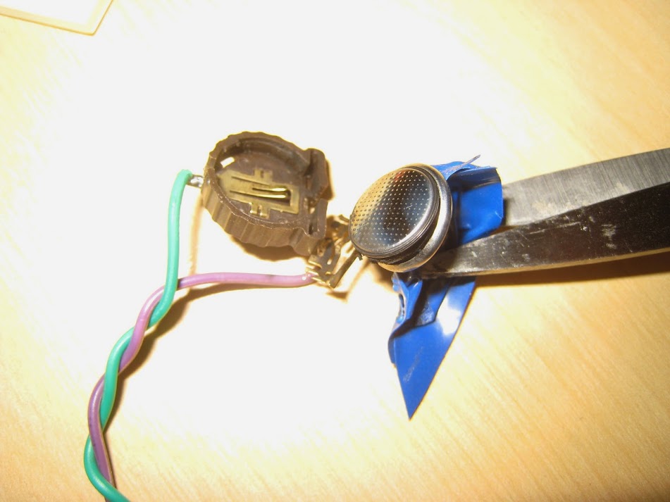
-32Khz crystal for RTC, vBAT pin is shorted with 3v3 ![]()
-Native USB for the STM32, with 1k5 pull up resistor.
-I2C eeprom.
-OLED display connector, wired to SPI2.
-Led in PC13
-button in (if I remember right) PA0, closed to ground.
-Reset button
Nice additions, it came with a usb cable and a few 20cm female/female wires like in the pictures
I compiled the new boot loader to use the led in PC13, and the button active low in PA0, and works fine.
http://detail.tmall.com/item.htm?id=44399907495
It has an C8T6 CPU (64Kb of flash officially, 128KB really).
It includes the following features:
-32Khz crystal for RTC, vBAT pin is shorted with 3v3 ![]()
-Native USB for the STM32, with 1k5 pull up resistor.
-I2C eeprom.
-OLED display connected, wire to SPI2.
-Led in PC13
-button in (if I remember right) PA0, closed to ground.
-Reset button
Nice additions, it came with a usb cable and a few 20cm female/female wires like in the pictures
I compiled the new boot loader to use the led in PC13, and the button active low in PA0, and works fine.
http://detail.tmall.com/item.htm?id=44399907495
It has an C8T6 CPU (64Kb of flash officially, 128KB really).
It includes the following features:
-32Khz crystal for RTC, vBAT pin is shorted with 3.3V with resistor 0 ohm R9. Remove it to have a functional Vbat pin.
-Native USB for the STM32, with 1k5 pull up resistor.
-I2C eeprom.
-OLED display connected, wired to SPI2.
-Led in PC13
-button in (if I remember right) PA0, closed to ground.
-Reset button
Nice additions, it came with a usb cable and a few 20cm female/female wires like in the pictures
I compiled the new boot loader to use the led in PC13, and the button active low in PA0, and works fine.
I have been on Arduino for a few months and stumbled on this site. Very interested in the STM32 for arduino.
I got the same board from Aliexpress. http://www.aliexpress.com/item/STM32F10 … 23680.html
Also got this http://www.aliexpress.com/item/Small-sy … 31494.html
The board is not recognized on my Win7 notebook. I have tried using my Pololu AVR programmer to program via serial pins PA9 and PA10. With no results. Also tried STM Demonstrator GUI (STMdownloader) always getting timeout errors. Please help! Hope you can provide a step by step guide of how you got the bootloader programmed in this unit.
Thanks,
Chris
What link settings are you using for Boot0 and Boot1
To upload via serial you must have boot0 high and boot1 low, (if boot1 is floating you will get random results)
With boot0 and boot1 set correctly reset the board and try stm’s flash loader demonstarator again.
If it doesnt work, check you have RX and TX around the right way, even try swapping them over.
Its probably worth looking at my youtube video’s just search yourtube for Arduino STM32 and you should find it, (one of the 3 covers uploading via serial I think)
Thanks for the quick response.
For the smaller board. There is no BOOT1. Which pin is this tied to?
Yes, I put BOOT0 high. I did hit the RST button. I did swap the TX/ RX as well. I did go through your youtube videos as well ![]()
I am running out of ideas!
http://www.st.com/web/en/resource/techn … 161566.pdf
According to AN2606, the rom bootloader is selected with:
Boot0(Pin) = 1 and Boot1(Pin) = 0
If I remember right, the bootloader works at 115200 bauds, but try other speeds if that doesn’t work.
The process should be like this:
1st. Set boot0 high and boot 1 low.
2nd. connect your RX and TX lines to usart 1 and power the board.
3rd. Open the Bootloader Demonstrator Gui, go thru the screens to select the file etc, and when ready to connect, reset the board, and the bootloader gui should detect it.
I mostly use st-link, but I have used the bootloader demonstrator in Windows without any problem too, so I second Rogers advice to make sure your TX and RX and connected successfully. And make sure you use a serial adapter that works at 3.3V.
Try a few different baud rates, i.e 56k as well as 115k.
Set the timeout to 1 second, it will help if you keep needing to retry.
Try pressing reset 2 or 3 times, Strangely this seems to help on my Red Pill board.
Also try power cycling, as sometimes this seems to be the only way to reset.
The other big unknown is the device you are using as usb to serial. You may need to use a dedicated usb to serial adaptor.
BTW. I have managed to use a Uno to flash via serial, using a sketch, and software serial, but its a bit hit and miss as well, because software serial doesnt support even parity, so i think its a fluke it seems to work.
Do you have an AVR arduino with a removable atmega 328p, that you could remove the atmega and use the fdti usb to serial chip on the uno etc, by connecting pins 0 and 1 to the STM32?
I am sharing the pinout info from OlliW.eu I find this a useful reference. It also shows all the 5V tolerant pins shown as FT. So using a 5V serial adapter should be ok.
I am doing this on a “roadtrip” so out of my “den” where I have other tools to use!
I tried various baud rates taking the additional step to change it in synchrony for the Pololu programmer under Device Manager. Still no progress. Setting BOOT0 and BOOT1 to OV -unit still runs the original blink program.
I will report back next week of any progress.
STlink’s are less than $10 and are pretty useful for these boards, as they can connect even when the board is in reset


