Most boards have a 32,767 Hz oscillator or crystal on them and therefore only need a battery/battery holder (possibly with an in-line schottky diode, put probably not) to allow us to get the RTC operational.
What I have discovered so far.
1) There is some sort of attempt to get this working in ./hardware/Arduino_STM32/STM32F1/libraries/Untested/RTClock/
This is incomplete and incompatible with the current versions of rcc.c and rcc.h
There is a “new” version of the rcc libraries in ./hardware/Arduino_STM32/STM32F1/libraries/Untested/RTClock/new RCC/
This is not compatible with the current rcc libraries either.
2) I am unclear which rcc.[h,c] I need to try to merge or adapt the changes form “new RCC” to as there seem to be a number of candidates.
./hardware/Arduino_STM32/STM32F3/cores/maple/libmaple/stm32f3/include/series/rcc.h

./hardware/Arduino_STM32/STM32F3/cores/maple/libmaple/stm32f3/f3_rcc.c
./hardware/Arduino_STM32/STM32F3/cores/maple/libmaple/include/libmaple/rcc.h
./hardware/Arduino_STM32/STM32F3/cores/maple/libmaple/rcc.c
./hardware/Arduino_STM32/STM32F1/libraries/Untested/RTClock/new RCC/rcc.h.new
./hardware/Arduino_STM32/STM32F1/libraries/Untested/RTClock/new RCC/rcc.c.new
./hardware/Arduino_STM32/STM32F1/libraries/RTClock/new RCC/rcc.h.new
./hardware/Arduino_STM32/STM32F1/libraries/RTClock/new RCC/rcc.c.new
./hardware/Arduino_STM32/STM32F1/cores/maple/libmaple/rcc.c
./hardware/Arduino_STM32/STM32F1/system/libmaple/stm32f2/include/series/rcc.h
./hardware/Arduino_STM32/STM32F1/system/libmaple/include/libmaple/rcc.h

./hardware/Arduino_STM32/STM32F1/system/libmaple/stm32f1/include/series/rcc.h
./hardware/Arduino_STM32/STM32F4/cores/maple/libmaple/rcc.c
./hardware/Arduino_STM32/STM32F4/cores/maple/libmaple/rcc.h
./hardware/Arduino_STM32/STM32F1/system/libmaple/include/libmaple/rcc.h
./hardware/Arduino_STM32/STM32F1/system/libmaple/stm32f1/include/series/rcc.h
http://www.keil.com/download/docs/356.asp
Well, sticking a 32K crystal on PC14 to PC 15 while the Maple Mini was on breadboard (extra capacitance) produced
Time + interrupt counts: 10.457 (10, 0, 1, 1)
Time + interrupt counts: 13.20437 (13, 0, 1, 1)
Time + interrupt counts: 15.7575 (15, 0, 2, 2)
— alarm —
Time + interrupt counts: 18.4175 (18, 0, 2, 2)
Time + interrupt counts: 21.24113 (21, 0, 2, 2)
Time + interrupt counts: 23.11238 (23, 0, 3, 3)
— alarm —
Time + interrupt counts: 26.7796 (26, 0, 3, 3)
Time + interrupt counts: 29.27733 (29, 0, 3, 3)
Time + interrupt counts: 31.14860 (31, 0, 4, 4)
— alarm —
Time + interrupt counts: 34.11417 (34, 0, 4, 4)
Time + interrupt counts: 37.31305 (37, 0, 4, 4)
Time + interrupt counts: 39.18424 (39, 0, 5, 5)
— alarm —
Time + interrupt counts: 42.14973 (42, 0, 5, 5)
Time + interrupt counts: 44.2090 (44, 0, 5, 5)
Time + interrupt counts: 47.22008 (47, 0, 6, 6)
— alarm —
Time + interrupt counts: 50.18555 (50, 0, 6, 6)
Time + interrupt counts: 52.5669 (52, 0, 6, 6)
Time + interrupt counts: 55.25597 (55, 0, 7, 7)
— alarm —
EDIT:
Looks like PC14 & PC15 (D13 & D12 respectively) on the Mini or D22/D23 on the Maple
I was looking over the older, Maple examples for RTC. This one compiles for me, but I do not have a 32K crystal on a Maple Mini to try… I need to find a schematic and determine if I can easily mount one under the magnifying glass….
C:\Users\Ray\AppData\Local\Temp\build7347767204266594424.tmp\RealTimeClock.cpp.bin :
section size addr
.data 16880 0
Total 16880
Binary sketch size is reported above. Check it against a 108000 byte maximum.
/*

*  test-rtc.c

*

*  Example program that sets up the Real Time Clock and then blinks the

*  LED in patterns for seconds and alarm interrupts.

*

*  Created by  Rod Gilchrist on 11-12-24.

*  section    size   addr

.data   16880      0

Total   16880

*/
#include "wirish.h"
#include "rtc.h"
#include "usb.h"
int globAlmCnt = 0;
int globOvCnt = 0;
int globSecCnt = 0;
int specAlmCnt = 0;
int lastGlobAlmCnt = -1;
int lastSpecAlmCnt = -1;
void rtc_sec_intr() { if (rtc_is_second()) globSecCnt++; }
void rtc_ovf_intr() { if (rtc_is_overflow()) globOvCnt++; }
void rtc_glob_alm_intr() { if (rtc_is_alarm()) globAlmCnt++; }
void rtc_spec_alm_intr() { if (rtc_is_alarm()) specAlmCnt++; }
void setup() {
pinMode(BOARD_LED_PIN, OUTPUT);
delay(5000);
SerialUSB.println("begin RTC blink");
delay(1000);
rtc_init(RTCSEL_LSI);
rtc_set_prescaler_load(0x7fff);
rtc_set_count(0);
rtc_attach_interrupt(RTC_SECONDS_INTERRUPT, rtc_sec_intr);
rtc_attach_interrupt(RTC_OVERFLOW_INTERRUPT, rtc_ovf_intr); // expected every 128000 seconds
rtc_attach_interrupt(RTC_ALARM_GLOBAL_INTERRUPT, rtc_glob_alm_intr);
rtc_attach_interrupt(RTC_ALARM_SPECIFIC_INTERRUPT, rtc_spec_alm_intr);
}
void loop() {
int i,n;
SerialUSB.print("Time + interrupt counts: ");
SerialUSB.print(rtc_get_count());
SerialUSB.print(".");
SerialUSB.print(rtc_get_divider());
SerialUSB.print(" (");
SerialUSB.print(globSecCnt);
SerialUSB.print(", ");
SerialUSB.print(globOvCnt);
SerialUSB.print(", ");
SerialUSB.print(globAlmCnt);
SerialUSB.print(", ");
SerialUSB.print(specAlmCnt);
SerialUSB.println(")");
delay(1000);
digitalWrite(BOARD_LED_PIN, 1);
if ((lastSpecAlmCnt != specAlmCnt) || (lastGlobAlmCnt != globAlmCnt)){
lastGlobAlmCnt = globAlmCnt;
lastSpecAlmCnt = specAlmCnt;
SerialUSB.println(" -- alarm -- ");
for (i=0;i<3;i++) { digitalWrite(BOARD_LED_PIN, 0); delay(100); digitalWrite(BOARD_LED_PIN, 1); delay(100);}
n = rtc_get_count() + 5;
rtc_set_alarm(n);
}
delay(1000);
digitalWrite(BOARD_LED_PIN, 0);
}
Sketch uses 20,268 bytes (18%) of program storage space. Maximum is 110,592 bytes.

Global variables use 4,552 bytes of dynamic memory.
But each time you post it I have to go through and change all ‘\’ in the #includes to ‘/’
Please library writers … use ‘/’ for path separators. It works on windows and linux and os/x .. the ‘\’ only works on windows.
Please library writers … use ‘/’ for path separators. It works on windows and linux and os/x .. the ‘\’ only works on windows.
I’m sure there must be a regex replace to do that ![]()
But I agree… All libs need to be cross platform.
RCC.h is correct:
#include <libmaple/libmaple_types.h>

#include <libmaple/bitband.h>
When you validate rcc.h and the RCClock lib, please stick a notice in the libraries section of the forum. I do not wish to do this prematurely. Oh, at that time you can remove the Untested directory in the libraries.
Ray
I really don’t think the IDE should be have anything to do with this. This is a C/C++ compiler issues and how to deal with cross platform development.
I agree.
Classic problems are .
1. Case sensitivity of Unix and not Windows systems, hence always use lower case
2. Don’t use spaces, where possible use underscore. (I’m not sure about the minus character instead of underscore). AFIK The reason that web sites tend to use the minus instead of an underscore is because the way Google parse URLS, as “Arduino_ST32” is treated as if its a whole word by Google, where as “Arduino-stm32” is treated as “Arduino” “stm32”
3. I think one problem is that some parts of windows force you to use back slashes, e.g. I think the PATH env var needs back slashes, but of course this completely screws up Linux and OSX which treat them as an escape symbol ![]()
Thanks.
Thanks.
Like changing anything in the core files, or the function or any pin…
Classic problems are .
1. Case sensitivity of Unix and not Windows systems, hence always use lower case
2…….
I will try to update the Rtc lib in the repo this weekend and move from untested
As a bit if history… I originally decided to collect all the libraries I could find that claimed to have been ported to libmaple and put them in the libraries folder, just to make it easier for people to find them
However I soon realised that a lot of them didn’t work, or perhaps never really worked correctly. Hence the untested folder
IMHO I think the untested folder seems to be a reasonable location for things until someone gets time to test and fix etc, as in some cases the libs are related to specific hardware that only a few people have.
I think its getting to the stage were its impossible for me to test everything, as it would be a full time job and I’d need to buy all sorts of hardware and connect it up in permanent test rigs.
So I think we will have to trust people when they say that something works for them if it involves external hardware
I can of course test any code that just uses standard features in C,R,V or Z series boards
Thanks
Roger
The example seems very rough, had toggle led on it which has been removed from the latest repo, did not have a Serial.begin(), and referred to SerialUSB which did not work in my case, not sure if because the board selection or what.
After I changed a couple of things in the example, its working and giving me a second counter.
I’ve got some button cells and holders somewhere so all I need to do is find the time to solder a few wires. Hopefully tomorrow.
The RTClock lib is now in the libraries folder.
I’ve converted it to the new style library, with a src subfolder and added keywords but I’ve just realised that the keywords dont all work.
I’ll fix this later, as its only a minor issue
Anyway, I’ve updated the Test_RTClock example so that it compiles on generic boards (removed toggleLed etc)
And I have tested both examples numerous times
Note. I’ve only tested on one board a generic F103C8, so it needs more testing on V and Z series etc just to be sure its ok
But I think its stable enough to move from the untested folder ![]()
Cheers
Roger
I fixed up the simple example, as it wouldn’t compile for me either ![]()
I fixed up the simple example, as it wouldn’t compile for me either ![]()
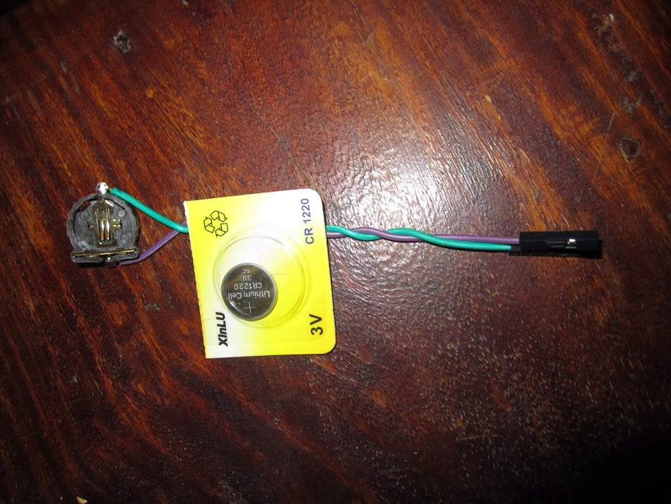
Battery holder, wires and battery.
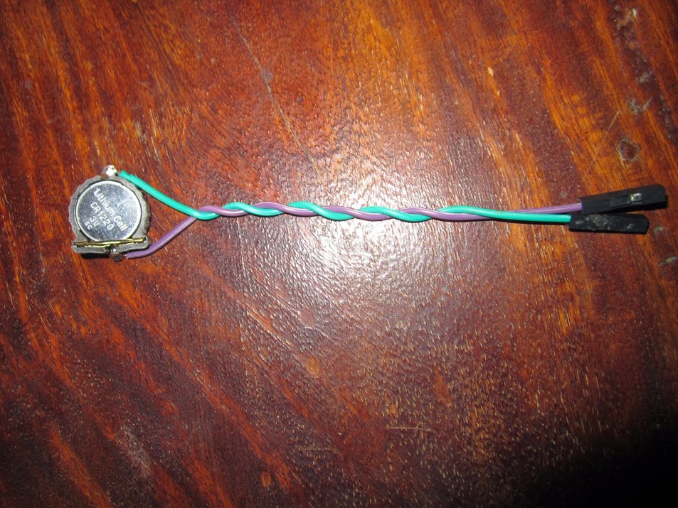
Battery fitted. In this case + VBat (aka 3VB) is the Purple wire, Ground is green.
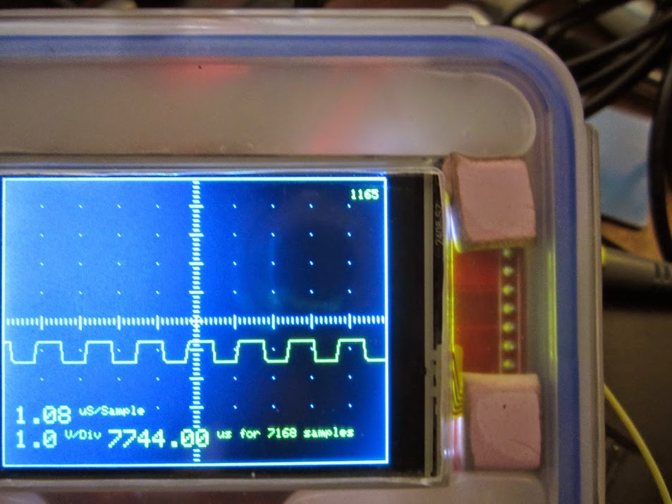
Number of seconds since the clock was reset is in the top right corner. This has been ticking away nicely, with the scope disconnected from power for the last couple of hours. Tick count is currently 23533 seconds since the battery was fitted and the clock reset.
I now need to refine this slightly to get HH:MM:SS DD/MM/YYYY and figure out how to trigger the alarms and get the STM32F103 to sleep. But the hard bit is done.

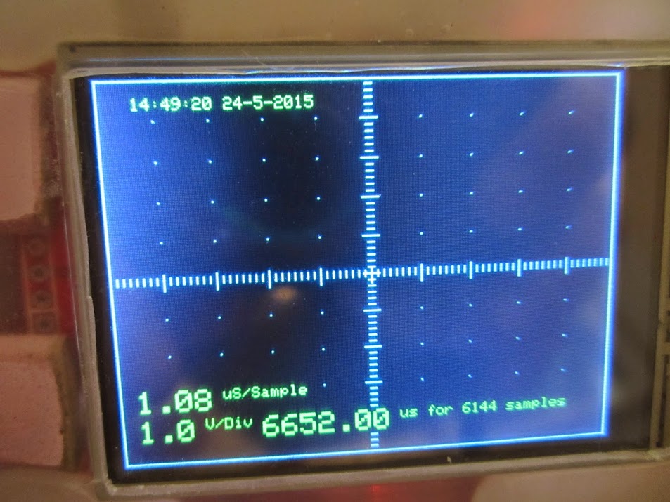
Slightly fuzzy shot of the battery holder wrapped in clear tape and popped in the project box. Wired to the GND and 3VB pins. 3VB note, not 3v3 !
WARNING Don’t wire the battery across the 3 Volt line or something will sizzle and pop, probably the battery, possibly the voltage regulator, maybe both, ![]() ensure you identify the correct pin for the RTC battery. The STM datasheet calls this pin VBat.
ensure you identify the correct pin for the RTC battery. The STM datasheet calls this pin VBat.
One interesting feature of the STM32F103 that is worth exploring are the battery backed up “registers”
The RTC and the backup registers are supplied through a switch that takes power either on VDD supply when present or through the VBAT pin. The backup registers are ten 16-bit registers used to store 20 bytes of user application data when VDD power is not present
EDIT: This link might provide some useful insights into using the RTC for human readable clock functions.
I looked in that doc, but couldn’t see anything , however it is documented in the main manual RM0090 on page 820.
I didn’t realise those registers existed. Using one of them for the bootloader could be very useful, so if we do make them available int the code, I’d like to reserve the last one for the bootloader for devices using the generic bootloader, as it allows us to reliably do uploads to ram without getting false positives
…
I didn’t realise those registers existed. Using one of them for the bootloader could be very useful, so if we do make them available int the code, I’d like to reserve the last one for the bootloader for devices using the generic bootloader, as it allows us to reliably do uploads to ram without getting false positives
Edit. The page number and doc I quoted before were for the F4, its on page 83 in the F103 doc (ref CD00171190.pdf)
It looks like they start at address 0x40006C00 + 0x04 and the spec says
20-byte data registers (in medium-density and low-density devices) or 84-byte data
registers (in high-density, XL-density and connectivity line devices)
• Status/control register for managing tamper detection with interrupt capability
• Calibration register for storing the RTC calibration value
• Possibility to output the RTC Calibration Clock, RTC Alarm pulse or Second pulse on
TAMPER pin PC13 (when this pin is not used for tamper detection)
I will initially see if I can get them working as an adjunct to the RTC but really they are not part of the RTC they are a core function of the processor and really need to be in cores and also have the number (size of memory) switched on an ifdef depending on device density.
I was thinking of placing a rolling unix timestamp in some of the registers to indicate the current time, starting with the time the clock is first set, and updated periodically by software using a per second ISR. Other bytes could be used for one or more alarm times. I hadn’t fleshed out the details. One idea would be to add some sort of sub second (millisecond perhaps) precision. Another enhancement would be to store a timezone value and keep the timestamp in UTC.
A little light reading for you all..
https://en.wikipedia.org/wiki/Unix_time
https://en.wikipedia.org/wiki/C_date_an … ons#time_t
http://playground.arduino.cc/code/time
http://www.pjrc.com/teensy/td_libs_Time.html
http://www.pjrc.com/teensy/td_libs_TimeAlarms.html
STMs own licensed device driver uses a slightly different approach, which seems more wasteful of the registers but I didn’t want to simply clone their idea as It may be possible to make this slicker. Perhaps self calibrating. I would prefer to stick to some sort of 32 bit time_t C typing standard so we have the option to use existing standard c time libraries with minimal re-working.
I was thinking more along the lines of some general easily accessible storage, rather than necessarily just using them for RTC
As far as I can tell from the manual, although some of the BKP registers are associated with the RTC, I got the impression that they are intended to store other data as well.
Did you see the note about tamper detection, i.e you can store sensitive data in these registers,and I presume they uP will erase them if it gets a tampered trigger.
Also. I was looking at a project a while ago that needed to store some calibration data, which may fit in these registers.
I know the EEPROM can be used as well, for that sort of storage, but its much harder to update, because you need to erase and re-write a page every time you want to change a byte. Where as these BKP registers although limited in size don’t seem to have that overhead
Yes, that is the intent that I ferret after a long read last night. The RTC domain already has registers associated with time, but not UNIX timestamp, but that would only take 2 16-bit registers. These registers, if one reads the entire manual, were intended to store critical memory variables when the uC was powered off or rebooted since this power domain is not reset if there is a backup battery attached.
Other than the last register that is intended to be reserved for the bootloader, I would suggest that R0 – R8 be wrapped so that a standard core library call could be used to get-set the registers. As the RTC, once set to the real time-date, has all of the necessary data to calculate the UNIX timestamp, I am not sure what benefit (other than code overhead on read, storing would be the same overhead), so maybe library or core lib to resolve and save the 9 16-bit registers for the application backup needs.
As the core code already has microsecond and millisecond counters, I really cannot see a need in having the UNIX timestamp anything but in unit seconds.
Just thinking out loud…
Ray
If however the RTC time register always counts from zero when reset , we would need a battery backed up 32 bit register to store an offset to the current time.
I can now set the time by sending
timestamp <unix time stamp>
It responds with
# Time command – 1432479737 15:2:17 24/5/2015(UTC)
The result is below.
Edit: Of course getting a valid unix timestamp is another matter. In Linux its pretty easy.
date –date “+1hour” +”%s”
Gives me UTC + 1hour – Which is what I need, since I am in British Summer Time (UTC + 1 Hour).
Since the STM32 RTC is a 32 bit int, I can set it read it display it and so forth using the following code snippets
Some where before setup() include the following…
...

// SeralCommand -> https://github.com/kroimon/Arduino-SerialCommand.git

#include "RTClock.h"

RTClock rt (RTCSEL_LSE); // initialise

uint32 tt;
// Time library - https://github.com/PaulStoffregen/Time
#include "Time.h"
#define TZ "UTC+1"
// SeralCommand -> https://github.com/kroimon/Arduino-SerialCommand.git
#include <SerialCommand.h>
...
Button cell <Select the CR1220 option
If we assume the typical current consumption which the STM32F103 datasheet (page 45) states to be around 1.5uA at between 25 – 60 C – and the typical capacity of a CR1220 cell is between 38mAh to 40mAh
Therefore our CR1220 cell should run (worst case) for 25333.333333333 hrs which is 1055.45 days, or 2.89 years. The battery should only drain if the equipment is not being powered so it should last longer if the equipment gets more usage.
However the cell will also self discharge to some minor extent (around 1% per year), which will shorten its life very slightly.
We are also draining such a tiny current that the cell capacity will effectively be greater (i.e. it should last longer).
Allowing for these factors, the above is a reasonable estimate.
My RCT board comes with a button cell, but I’ve no idea if its flat or not.
I’ll need to fire up the board this evening and test the new code.
My RCT board comes with a button cell, but I’ve no idea if its flat or not.
I’ll need to fire up the board this evening and test the new code.
You are right, Its soldered onto the bottom of the board, so is likely to be a NiCad button cell, so is probably charged via a simple resistor circuit
I will need to load the generic bootloader onto that board and give everything a try when I get chance
See here for the results of *not* checking first ![]()
If VBATT is at 3.3V you will need to put a schottky diode or some other protection depending on your battery type in series with the battery to protect it from inadvertent charging (i.e. exploding).
With the zero ohm resistor removed, no smoke, no loud noises and the RTC works as expected. Now what the logic of shorting that pin high was I have no idea. Possibly the original schematic called for a diode, but zero ohm links are cheaper… I would suggest a jumper rather than a link would have been a smarter call.
On another note, I understood in a post Andy wanted to get milliseconds from the RTC, I think that is possible by reading the current preescaler value, in registers RTC_DIVH / RTC_DIVL and dividing by the appropriate number. Page 481 of the datasheet, although as Roger pointed we already have other sources of milliseconds.
If the time library in arduino provides for a way to get milliseconds from it, then those registers could be used to get them here.
Can you give this code a try on your battery backed system ![]()
#include "RTClock.h"
#define BKP_REG_BASE (uint32_t *)(0x40006C00 +0x04)
static inline int readBKP(int registerNumber)
{
if (register>9)
{
register+=5;// skip over BKP_RTCCR,BKP_CR,BKP_CSR and 2 x Reserved registers
}
return *(BKP_REG_BASE+registerNumber)&0xffff;
}
static inline void writeBKP(int registerNumber,int value)
{
if (register>9)
{
register+=5;// skip over BKP_RTCCR,BKP_CR,BKP_CSR and 2 x Reserved registers
}
*(BKP_REG_BASE+registerNumber)=value&0xffff;
}
//#define TEST_WRITE
#define REG1 0
#define REG2 1
void setup()
{
Serial.begin(115200);
rtc_init(RTCSEL_LSI);
#ifdef TEST_WRITE
writeBKP(REG1,0x1234);
writeBKP(REG2,0x5678);
#endif
}
void loop() {
Serial.print("reg 1 ");Serial.println(readBKP(REG1),HEX);
Serial.print("reg 2 ");Serial.println(readBKP(REG2),HEX);
delay(1000);
}
I fixed an error where you had referred to register at one stage, and registerNumber at another, and I modified to allow me to use usb serial.
#include "RTClock.h"
#define BKP_REG_BASE (uint32_t *)(0x40006C00 +0x04)
// Create USB serial port
USBSerial serial_debug;
static inline int readBKP(int registerNumber)
{
if (registerNumber > 9)
{
registerNumber += 5; // skip over BKP_RTCCR,BKP_CR,BKP_CSR and 2 x Reserved registers
}
return *(BKP_REG_BASE + registerNumber) & 0xffff;
}
static inline void writeBKP(int registerNumber, int value)
{
if (registerNumber > 9)
{
registerNumber += 5; // skip over BKP_RTCCR,BKP_CR,BKP_CSR and 2 x Reserved registers
}
*(BKP_REG_BASE + registerNumber) = value & 0xffff;
}
// #define TEST_WRITE
#define REG1 0
#define REG2 1
void setup()
{
serial_debug.begin();
//Serial.begin(115200);
rtc_init(RTCSEL_LSI);
#ifdef TEST_WRITE
writeBKP(REG1, 0x1234);
writeBKP(REG2, 0x5678);
#endif
}
void loop() {
serial_debug.print("reg 1 "); Serial.println(readBKP(REG1), HEX);
serial_debug.print("reg 2 "); Serial.println(readBKP(REG2), HEX);
delay(1000);
}
.. so it works, the data survives the power being removed
My understanding is that these registers are cmos ram, I presume they are zero wait state, so they have all the advantages of ram and none of the disadvantages of flash.
That is my understanding, too. The silicon is laid out with different power domains, so the back-up battery powers the RTC domain and these registers are in that power domain.
Ray
Below it the result of writing 1234 5678 c5c5 5c5c 1235 5678 etc.. to the first 16 possible registers… as you can see 16 bit registers 1 to 10 work perfectly.
...

reg 1 1234

reg 2 5678

reg 3 C5C5

reg 4 5C5C

reg 5 1234

reg 6 5678

reg 7 C5C5

reg 8 5C5C

reg 9 1234

reg 10 5678

reg 11 0

reg 12 0

reg 13 0

reg 14 0

reg 15 0

reg 16 0

reg 1 1234

reg 2 5678

reg 3 C5C5

reg 4 5C5C

reg 5 1234

reg 6 5678

reg 7 C5C5

reg 8 5C5C

reg 9 1234

reg 10 5678

reg 11 0

reg 12 0

reg 13 0

reg 14 0

reg 15 0

reg 16 0

...
I did test that it survives a reset, which is handy in its own right.
LOL.
While I was looking at where we should put these functions, I found that there are already functions for them in the core code
bkp_f1.c
#include <libmaple/bkp.h>
void setup() {
// put your setup code here, to run once:
Serial.begin(115200);
bkp_init();
bkp_enable_writes();
//bkp_write(1,0x1234);
}
void loop() {
// put your main code here, to run repeatedly:
Serial.println(bkp_read(1),HEX);
delay(500);
}
It has ASSERTS in the code, but they don’t do anything except if DEBUG is turned on at e.g. in platform.txt
uint16 bkp_read(uint8 reg) {

__io uint32* dr = data_register(reg);

if (!dr) {

ASSERT(0);                  /* nonexistent register */

return 0;

}

return (uint16)*dr;

}
I can see the advantage of not always calling write_enable() but apart from always making the code a tiny bit bigger
As This is a core feature that all ST32’s have.
As your intent is to utilize the high register for the bootloader, that register must be masked from user write access anyway. I would go ahead and rewrite the function, mask the write to [9] for the F103 ([41] for high density) and set the error return to -1. Including in the startup code seems reasonable.
Ray
I think it will be easier to mask off the first register, so that when the API accesses register 1 its actually register 2, otherwise the code that has to skip the 5 control reg’s between the 2 blocks of bkp reg’s could be a bit confusing.
I’m not sure if the loss of one 16 bit reg for the bootloader is a big issue. But it would make the bootloader more flexible. In fact, we could treat this one “reserverd” register as some sort of special storage, as the bootloader would only need one or two bits of the 16 bits.
Also…
Leaflabs have coded this with register numbers starting at 1, which is in line with the hardware names, but I’m not entirely sure I like numbering from 1, makes sense.
Perhaps I should change the code so that we mask off first reg for use with the bootloader and then use “BKP_REG2” as register ( 0 ) in the code
Or, do you think that would be really confusing?
I think that definitely, initialising this as part of the normal RCC stuff, would not be a big overhead.
And I could always call bkp_write_enable when you do a write in the code. i.e to save having to remember to add that line.
After all, these functions are unlikely to be used for anything that is time critical, so having write take a bit longer is unlikely to cause any issues.
Looking at the real HAL names for this,
It would probably be better to change them to the STM standard
BKP_WriteBackupRegister(BKP_DR1, FirstBackupData);
and
BKP_ReadBackupRegister(BKP_DR1)
and do some defines for the BKP_DR’s
If the read/write routine reserves [0] for both medium & high density devices devices, I see no confusion. In fact, maybe mask off a byte for the bootloader and a byte for the user … uint8_t
So, user code can write to [0] but only as a byte. [1] … [9] on medium density and [1] … [41] on high density are user available.
I’m just rambling as I only see this area needed for run-time state preservation while the uC is powered on.
Ray
Cant found english manual for this. Only in Russian
http://spec-project.ucoz.ru/index/kalib … m32f1/0-14
to calibrate i need record bit 1 to BKP_RTCCR_CCO backup register.
example BKP->RTCCR |= BKP_RTCCR_CCO;
i correctly understand command will be
bkp_init();
bkp_enable_writes();
bkp_write(BKP_RTCCR_CCO, 0x1);
i try read after this
for (uint8_t iii=0; iii<20; iii++){
Serial.print(bkp_read(iii),HEX);
Serial.print(” “);
}
and read only zeros.
what i doing wrong?
but reading still return zero.
dont understand what i doing wrong
create pull request for this upgrade
https://github.com/hyperion11/Arduino_STM32/pull/1