I was lately trying to improve some SPI functions (speed optimization). I mostly used the new SDfat beta and everything worked nicely.
But then I was told that my improvements have some problems on ILI9341-based displays so that I wanted to buy an SPI controlled display board.
In my searches for an appropriate board I realized that Arduino compatible 2.4 inch touch TFTs with SPI interface have almost the same price as 3.5 inch 480×320 touch TFT display modules for RPi. I decided to buy one of these.
As the board arrived, I had hard time by identifying the on-board controller as no register read functionality is available on the board, tried several init sequences from the net.
At the end I figured out it must be an ILI9486.
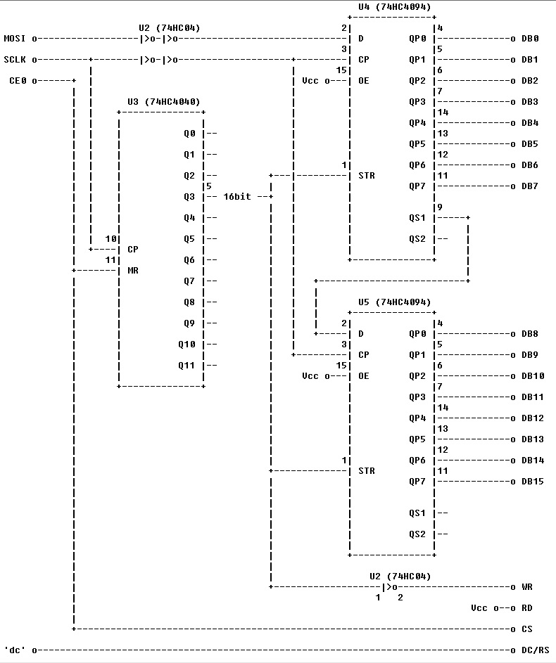
This board contains a serial->parallel conversion circuit, the ILI9486 is actually set up for 16 bit parallel write-only interface.
I decided to write an Adafruit-compatible library, and I took the ILI9341 lib from our repo as starting point.
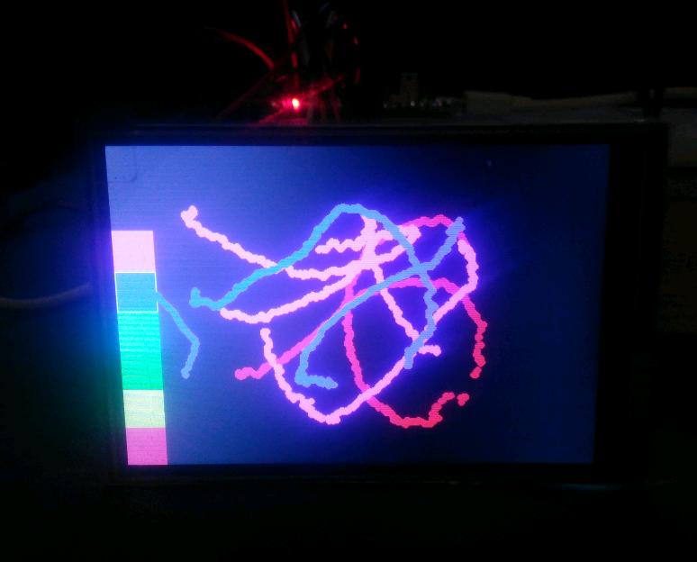
And here it is a very first working version.
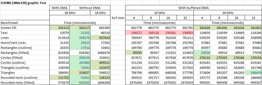
Using a graphic test sketch I could evaluate the performance of 16 bit writing at 36MHz SPI clock speed.
And this is the result:
***** ILI9486 graphic Test *****
************************************************
Without DMA:
************************************************
Benchmark Time (microseconds)
Screen fill 342137
Text 49898
Lines 544406
Horiz/Vert Lines 30606
Rectangles (outline) 19241
Rectangles (filled) 834795
Circles (filled) 298164
Circles (outline) 429518
Triangles (outline) 111944
Triangles (filled) 361198
Rounded rects (outline) 130705
Rounded rects (filled) 960236
Done!
************************************************
Now using DMA:
************************************************
Benchmark Time (microseconds)
Screen fill 341513
Text 52079
Lines 613614
Horiz/Vert Lines 31325
Rectangles (outline) 20255
Rectangles (filled) 833456
Circles (filled) 352232
Circles (outline) 429516
Triangles (outline) 136594
Triangles (filled) 386043
Rounded rects (outline) 131725
Rounded rects (filled) 973679
Done!
There are a bunch of HVGA screens around, but I’ve never taken the plunge and actually bought one.
I was looking at this, but it is unclear what controller is on it, but I suspect that it too uses the LI9486.
Its interesting to see that the SPI only versions are actually relatively fast. I would have thought parallel would confer some major speed advantages, but evidently they are in the same general ball park. That SPI with DMA is no advantage until you to things like block fills makes some sense though.
Maybe I need to rename the $10 pig-o-scope as the £10 pig-o-scope and upgrade from QVGA to HVGA ![]() after all, I have tried a smaller 1.4″ screen and that works, so why not go large.
after all, I have tried a smaller 1.4″ screen and that works, so why not go large.
I was wondering is the detection init sequence different for every chip?
I will download and test your latest code.
Its interesting that DMA is now slower in most cases. But we haver never been using DMA for its real purpose, which is allow the CPU to do something else while the transfer is running.
Ideally we should have non blocking DMA functions as well as blocking ( this could be done via an optional parameter)
Also, the nature of the ILI9341 SPI commands e.g to set individual pixels by sending address then value, is very inefficient, especially as the default Adafruit library does not buffer these transfers into one larger SPI transfer.
I think Paul rewrote huge chunks of the Adafruit code for use on the Teensy, and added buffering to achieve much higher speeds, but for most people what we currently have is adequate, hence no one needed to do the same thing with our version.
Most TFT controllers can be configured for 8-bit SPI. The minimum write-cycle is marginally faster with 8080 parallel-interface. The minimum read-cycle is faster with SPI than parallel. OTOH, SPI is easily controlled with DMA.
You can calculate the “best” time for any graphics operation by the datasheet cycle times.
Of course most graphics require software calculations. The STM32 can calculate while the bus traffic is handled by DMA.
The STM32 requires “slowing down” when you use 8080-parallel interface. You cannot drive an 8080 interface with DMA. So you can’t calculate and drive the bus at the same time.
Mind you, if the RPi display is converting SPI to 8080-16bit parallel in hardware, DMA should work just fine.
David.
But we cannot allow us this luxury, RAM is limited. So the biggest challange is how to optimize command and data selection.
I have some aproaches in my mind, the buffering could be implemented with not too much effort, have to check Paul’s version.
I tested the latest SPI updates and they seem OK, but please check your repo is up to date, as it looks like the changes to boards.txt and possibly others have not been pulled from my master HEAD to your fork.
Thanks
Roger
Btw, I further increased a bit the speed by reducing the window address setting part by 50% (from 18 us down to 8 us). I am now using entirely 16 bit accesses for register settings, too, without DMA.
***** ILI9486 graphic Test *****
************************************************
Benchmark Time (microseconds)
Screen fill 342102
Text 42270
Lines 456059
Horiz/Vert Lines 30056
Rectangles (outline) 18507
Rectangles (filled) 834569
Circles (filled) 259954
Circles (outline) 351849
Triangles (outline) 94697
Triangles (filled) 343390
Rounded rects (outline) 109572
Rounded rects (filled) 949488
Done!
Thanks, I will pull your version to my local branch and re-test.
I have a custom made PCB I am using for these tests, which has a maple mini on one side and the ILI9341 display on the other, so that the wires (pcb tracks) are quite short ( approx 3 cm)
BTW. I think the F103 spec max speed for SPI is actually 20MHz, but it normally seems to work OK at 36MHz.
I dont know the max speed of the display, it may also be less than 36MHz.
I think the best way for further increases in speed with the ILI9341 based display is via buffering multiple writes.
Using double buffering would allow the best use of DMA ( if we had a completion callback) as calculation of line, pixel and text drawing must be taking almost as much time as the SPI data transfer to the display
Mounting the controller board very close to the display should do the trick.
I have today implemented the buffering (with configurable size), I am currently debugging it ![]()
https://cdn-shop.adafruit.com/datasheets/ILI9341.pdf
page 231. Shows , “Serial clock cycle write” at 100nS min = 100MHz
So perhaps not all ILI9341 devices will run at 36Mhz as its considerably above the spec max speed.
And this mode should support ~10 MHz write strobes (page 226), which means a theoretical serial speed of 160 MHz…
I was having a look at those numbers, and I’m surprised too at getting the same speed with DMA and without, but I also noticed you can’t run the display at the max SPI speed.
Looks like your SPI optimizations are definitely a great improvement, and now the overhead is not that much. If you get to drive it at 36Mhz we will see if at that speeds the DMA starts getting some advantage or not.
A while back when porting the sd-fat library I did some tests with and without DMA at slower SPI speeds, and noticed pretty much the same, up to a certain point DMA was not faster than normal.
The bigger advantage as Roger said is the parallelism DMA allows, I did some test sketches with FreeRTOS and CoOS and using DMA for block transfers allowed a bit more time for other tasks, but again only for big block transfers. If you start drawing anything other that straight lines, there isn’t any advantage at all.
If I remember right, I did some test with the ILI library where it would only use DMA if the line to draw was longer than N pixels, and use the normal transfer for smaller lines, and found the minimum number of pixels for DMA to make a difference. Still the gains over using DMA all the time at full speed were not significant, but did show that normal transfers were faster if under a number of bytes.
As it runs without any error at 18MHz, I am confident that the sw works ok, it is just that the wires are too long.
The non-DMA version has no more clock gaps between consecutive writes, that is why the runtime is identical or better with the DMA version. It has no overhead, but is interrupted by systick and USB irqs, wherein the DMA version is not.
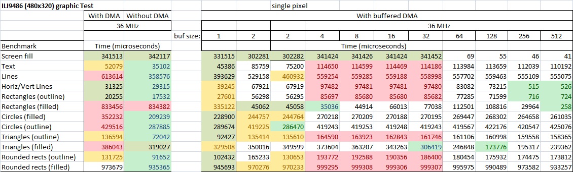
The biggest issue with the buffered version I am developing are the single pixel writes: there is no speed gain because the register writes are performed without DMA due to command and data selection, but it must run through the buffer as all other writes as well in order to avoid conflicts between buffered and non-buffered writes. On the other side, they are filling up quickly the buffer so that, again, the buffering doesnt offer too much advantage…
The non-DMA version has no more clock gaps between consecutive writes, that is why the runtime is identical or better with the DMA version. It has no overhead, but is interrupted by systick and USB irqs, wherein the DMA version is not.
Regarding the buffering, I think I am on the good way to have it, there is only one HUGE issue…
I am struggling the whole day with the DMA IRQ and SPI…
I really need some help here
It seems that the SPI peripheral freezes after the DMA finished its job. Checking the TXE and BUSY flags in the DMA isr routine:
	while (spi_is_tx_empty(_currentSetting->spi_d) == 0); // "5. Wait until TXE=1 ..."

/* and */

while (spi_is_busy(_currentSetting->spi_d) != 0); // "... and then wait until BSY=0 before disabling the SPI."
http://www.ebay.com/itm/281672772523
It looks like an Uno R3-style HVGA 8080 interface with touch screen featuring an ILI9488 controller, but the init code they do provide is for an ILI9327.
I ordered one an let you know how it works.
http://www.ebay.com/itm/281672772523
It looks like an Uno R3-style HVGA 8080 interface with touch screen featuring an ILI9488 controller, but the init code they do provide is for an ILI9327.
I ordered one an let you know how it works.
But this one can be shipped to Germany (although a bit larger and more expensive): http://www.ebay.com/itm/172354640099
The same mcufriend display, but even cheaper -> http://www.ebay.com/itm/TFT-LCD-Display … Sw5cNYGU4A
GBP 5.15 Approximately US $6.30
OK, me too prefers SPI but I do not understand all this effort to get a RPI one run…
Of course, the SPI definitely uses less pins (it can be mitigated if you consider the touchscreen, though), but what are the consequences in terms of speed?
Is DMA usable in both cases, and if yes, is there a real gain using it, or as I understand it, does it depend on how you use it?
Given that we can’t afford to have a frame buffer inside the STM32, should we add an external RAM like in the Discovery kits (I really doubt…), use a sprite technique to blit rectangular areas into the controller, or draw graphic elements on the fly or even pixel by pixel, try to buffer these, etc.?
In normal use case to draw some buttons and some text, you will not necessarily need DMA.
If you read the first post in this thread, you realize that with the current SPI lib, there is no speed gain when using DMA.
Interesting would be to compare (graphic test) two boards with identical controller and resolution, one driven by SPI and the other 8/16 bit parallel.
As I only have one 240×320 8 bit parallel (ILI9327) display and one 320×480 SPI (ILI9486) display, the comparison is not very relevant.
As reference, my benchmark for the 8 bit parallel.
DMA would only make sense in applications where you could consistently use the time used by DMA to write to SPI for other purposes. In this case the DAM should be buffered.
I am currently working on the buffering method, there are still some bugs to resolve.
As a preliminary information, drawing characters with buffered DMA causes a huge speed decrease (200-300%)… The overhead to store the pixel data into buffer makes the drawing much slower than with simple drawing without buffered DMA.
Is DMA usable in both cases, and if yes, is there a real gain using it, or as I understand it, does it depend on how you use it?
..
Re: Quality of these displays
It looks a lot like they may be salvaged from old mobile phones, I had similar issues with the Nokia 5110 displays from eBay as a lot of them are not actually “new” (as advertised), they are salvaged and are often not even cleaned so were covered in whatever grime was in the mobile phone form years of use
As a preliminary information, drawing characters with buffered DMA causes a huge speed decrease (200-300%)… The overhead to store the pixel data into buffer makes the drawing much slower than with simple drawing without buffered DMA.
Another way to take advantage is to not use the core DMASend function, but rather write your own where you set all common parameters only once (circular buffer, address for buffer, enable DMA for the peripheral, etc) where the only thing you need to do is set the length of the transfer and fire the DMA, since the rest of the parameters are the same all the time, and no need to enable and disable DMA every time, set the ISR or anything else that’s common.
Let’s say you have 8 bit parallel interface, and one byte is transferred within 1usec; this is equivalent to an SPI speed of 8MHz. Any SPI speed above this is winner.
For 16 bit parallel interface, if 1 word transfer lasts 1usec, then this equals to an SPI speed of 16MHz. An application where the SPI clock is 36MHz is more than 2 times faster.
Wherein a 16 bit parallel interface is 2 times faster than an 8 bit parallel interface.
For parallel transfers, to calculate one data transfer you have to add the time to write the data to the IO port (in ideal case you have all data pins on the same GPIO port), the time to set WR line low, then set WR high again.
For simplicity I assume that the writing the window addresses would take same amount of time in both serial and parallel.
Your comparison makes only sense if you compare same graphicstest software running on the same controller board (MM or blue pill) controlling same display controller (ILI9341?), driving same display resolution (320×240) in two different modes (parallel and serial at maximum possible speed).
Btw, where did you get the ILI9341 parallel benchmark from?
http://www.stm32duino.com/viewtopic.php … 180#p17524
But as I said, it is really comparing apples to oranges, and for the results to be significant, you will need to make sure all other parameters (controller, screen size, etc.) are consistent.
stevestrong wrote:Let’s say you have 8 bit parallel interface, and one byte is transferred within 1usec; this is equivalent to an SPI speed of 8MHz. Any SPI speed above this is winner.
Actually, it is using an RC circuit with t = 150 ns that may or not be masked by the following byte, depending if WR is edge or level-triggered in the controller
This would provide a “sprite” transfer capability, cut out from a single source containing image and transferred through DMA to the display at the desired destination position. With little modifications, this could be used for fixed/variable font rendering too.
Here is a proposed prototype:
// blit a rectangular area from a source image

void Adafruit_ILI9341_STM::blitRect(uint16_t *src, int16_t wrap, int16_t x, int16_t y, int16_t w, int16_t h);
Actually, it is using an RC circuit with t = 150 ns that may or not be masked by the following byte, depending if WR is edge or level-triggered in the controller
The ILI9486 specifies a WR cycle time of 50 ns min. (twc in datasheet, page 212), thus you are limited to 20 MHz on the 8080 interface side. The limit will be the HCT chips at the given VCC.
The ILI9486 specifies a WR cycle time of 50 ns min. (twc in datasheet, page 212)…
Well, I am not convinced that it was the time worth.
Here is the benchmark:
- ILI9486_SPI_benchmark_compare.jpg (185.66 KiB) Viewed 763 times
DMA can be from memory to memory. Since the GPIO are just registers in memory, DMA can write to parallel ports. I am sure the STM forums have some examples, but in any case I dont think it should be too complicated.
Other than the destination address, which you make circular to a single address matching the port you want to write to, the rest of the setup is exactly as what we do in the SPI DMASend functions. I.e:
Select a DMA channel
set it up with source, destination, whether the addresses increase or not (shouldn’t for dst, and should for buffer source)
attach an ISR to the DMA channel
enable interrupt on complete or half complete or both
fire transfer
If I remember right all channels in both controllers in the STM32f103cbt can do Mem-Mem transfer, which should apply to mem-gpio transfer.
Has been a while since I read all the DMA stuff, but that is more or less what I remember if it can be useful.
EDIT:
This thread was just linked in another discussion, and happens to show exactly how to do DMA transfer to GPIO:
http://www.stm32duino.com/viewtopic.php?f=18&t=1042
It shows the ping was toggling at 4Mhz. I am almost sure the GPIO ports can be set to a faster speed than that, and I believe there is an older thread where Roger mentioned more details.
In the current version the pin toggling is done on “main” level, meaning that it holds the main level from its job.
I will try to push the window address writing to be handled exclusively with DMA accesses.
But it looks very complicated (almost impossible) to marry the GPIO DMA with SPI DMA…
- ILI9486_SPI_benchmark_compare.jpg (197.61 KiB) Viewed 732 times
1. set a 1×1 rectangular window. write one pixel
2. set a rectangular window. write the same colour to every pixel. e.g. drawLine or fillRect
3. set a rectangular window. write different colours to each pixel. e.g. pushColors from Flash or SRAM
Any operation consists of a command + variable amount of data. You have to set the DC pin at the correct time.
DMA can make a dramatic difference to the GRAM_WRITE data part of (2) and (3)
Most other command + data operations are trivial in size and require setting the DC pin.
Drawing curved lines or transparent text involve individual drawPixel() calls
Drawing solid text can use (3) but note that the Adafruit_GFX library does not use this optimisation.
As far as I can see, your RaspPi display is not readable. So does not seem very attractive.
I presume that your “36MHz” means the F103 is running at 72MHz with SPI SCK at 36MHz
David.
The board is designed for RPi, so it should support at least 80 MHz.
Btw, on board are HC chips, not HCT.
The 50MHz is about the gpio “signal edges” – you may set the driver strengths.
I think, with short wires from controller board to display board, an SPI clock of 36 MHz should perform without problems.
I ran Sdcard on SPI1 @36MHz with 21cm long wires fine.. Do use shortest wires possible, of course
HC chips have a minimum fmax
You may reach 36 MHz with short wires and direct connection w/o breadboard @ 25°C, but you are taking your chances (thus the corrupted display).
And I don’t see how you can reach a reliable 80 MHz operation for RPi using these HC chips.
From fbtft sources, the RPi looks like it is driving this display @ 32 MHz, but this is using a full continuously refreshed frame buffer, so a glitch won’t be as noticeable as it will be redrawn on next frame anyway.
However the spec for native SPI interface of Ilitek controllers seem to say:
ILI9320: tSCYCW >= 100ns, tSCYCR >= 200ns.
ILI9325: tSCYCW >= 100ns, tSCYCR >= 300ns.
ILI9325D: tSCYCW >= 50us, tSCYCR >= 200us. //surely must be typo
ILI9341: tWC >= 100ns, tRC >= 150ns.
ILI9481: tWC >= 100ns, tRC >= 300ns.
ILI9486: tscycw >= 66ns, tscycr >= 150ns.
This implies that you can sustain SCK frequency <= 120MHz for an ILI9486
Or <= 80MHz for ILI9341 and ILI9481
My experience with ILI9341 seems to verify 80MHz is ok with an ESP8266.
The STM32F103 is limited to SCK=36MHz anyway.
I do not have a RaspPi. Nor do I have a RaspPi TFT shield.
Do they all use 74HC4040 and 74HC4094?
Or other shift register scheme?
Or do some use the regular SPI interface?
I possess an SPI ILI9320. The DC signal is in an escape byte. So it looks more amenable to DMA. I have never tried it.
David.
That’s interesting! I wonder which other ILI controllers have the same. That could make for really fast display drivers even with small buffers, and minimal cpu usage.
Just had a look at the ILI9341 datasheet, and supports a mode without D/C line, I guess there is some track cutting and soldering involved to reconfigure the display. Looks like the serial mode without DC line in the ILI9341 is serial 9bit, which complicates things in other ways ![]()
Still interesting for whichever controllers support it.
e.g. ILI9326, R61509 and other non-MIPI controllers
It is slower than using separate control lines but at least you can use 8-bit SPI hardware.
You still need the CS to synchronise for the next command after a data burst.
MIPI controllers like ILI9341 have a 9-bit serial interface.
It is a nightmare with most microcontrollers. Very few have variable width SPI. And you are forever changing between 9-bit, 8-bit, 16-bit SPI.
Do all the RaspPi shields use the SPi to 8080 scheme described in the Original Post?
16-bit modules are more common on the surplus market. The often have no access to the IM# lines. So you can not configure them for native SPI.
David.
ILI9325: tSCYCW >= 100ns, tSCYCR >= 300ns.
ILI9325D: tSCYCW >= 50us, tSCYCR >= 200us. //surely must be typo
ILI9341: tWC >= 100ns, tRC >= 150ns.
ILI9481: tWC >= 100ns, tRC >= 300ns.
ILI9486: tscycw >= 66ns, tscycr >= 150ns.
This implies that you can sustain SCK frequency <= 120MHz for an ILI9486
Or <= 80MHz for ILI9341 and ILI9481
So all my “frequencies” are wrong by a factor of 8.
Having said that, real-life ILI9341 controllers with SPI interface seem to work reliably at 80MHz!
And if you use the 8080 interface, twc=66ns, trcfm=450ns. And these values are reflected in real-life. You get glitches if you run too fast.
I possess ILI9225, ILI9320, ILI9341 with 4-wire SPI, ILI9481 with 3-wire SDIO (bidirectional)
SPI modules are less common than 8080 parallel.
David.
Yes, because of this, fast TFT screen circuits are using 8 or 16-bit parallel modes, since the controller built-in 3 or 4-wire SPI modes are getting roughly the same toggling speed, you get transfer performance divided by 8 or 16.
However, the RaspPi shield discussed here is performing an external SPI to 16-bit parallel conversion using 74HCxx chips to get faster transfer speeds with the limited number of available GPIO pins and DMA modes on the Pi. The WR pulse is auto-generated by the 74HC4040, but the drawback is that there is no read mode as RD is is not controlled and tied to Vcc. Not a problem for the RaspPi, since it keeps an internal full frame buffer, but rather annoying when using no buffer like here, since it prevents read-before-write transparency mode.
And although the RaspPi is driving the SPI @ 32 MHz which is above the guaranteed maximum frequency, it is still in the typical achievable ones, and as again the Pi is using a full frame buffer with continuous refresh, a glitch will get unnoticed, whereas the way the Arduino TFT library uses it is completely different, and pushing the transfer frequency to the limits will result in corrupted displays (if in data mode) or may hang the controller (if in register mode).
However, I am really surprised the the ESP8266 can drive an ILI9341 at 80 MHz. I know its CPU is clocked at this speed and that it can be overclocked to 160 MHz without problem, and that the SPI bus can too reach an 80 MHz speed and contains deep FIFOs able to keep up with SPI Flash transfer speeds, but this is only possible if you are using SPI in master mode with DMA. Have you measured this actual speed with an oscilloscope?
It seems perfectly believable that a controller can execute a command in x ns.
Whether it received the command by 8080 bus, 6800 bus, SPI, … is immaterial.
If anything, it should be able to implement its SPI decoding faster and more efficiently in its own Silicon. OTOH, the twrh=40ns and twrl=40ns clearly show SCK speed limits.
I don’t have a fast oscilloscope or Logic Analyser. But it should be simple enough to just rely on ILI9341 fillScreen() times. i.e. 240 x 320 x 16 bits / SCK frequency = 16ms @ 80MHz.
The Adafruit test is 5 fillScreens so I should expect 80000us.
For Steve Strong’s 320×480 display @ 36MHz, I would expect 342000us. And that is exactly what he got!
Instead of erroneous speculation, I will test these figures with real hardware tomorrow.
David.
Please let us know about the results!
162024us for 80MHz
157946us for 160MHz
So my first guess is that Bodmer’s library is using the SPI library. And the SPI library limits SCK frequency to 40MHz. Edit. Bodmer’s User_Setup.h file specifies maximum 40MHz for SCK
The Totals for all the Adafruit Tests are 2.10s for 80MHz and 1.66s for 160MHz.
This implies that the faster calculation speed improves the time. The Lines test is calculation intensive:
320608us for 80MHz
202668us for 160MHz
In an ideal world, all the calculations are performed during the time that DMA is blitting the bus.
i.e. you are solely limited by bus speed.
All ARM chips are capable of “no gap” SPI. So you can achieve full speed SPI without DMA. FillScreen requires no work. I should be able to get the same times without DMA
The AVR SPI peripheral always has “gaps”. The AVR USART_MSPI peripheral can achieve full speed with no gaps. Of course you need a good Arduino SPI library to get the best out of the hardware.
Time for a cup of tea. And inspection of Bodmer’s library.
I am predicting serious Humble Pie. i.e. my previous assertions about 80MHz SCK look pretty silly.
Edit. I can set max SCK to 80MHz in User_Setup.h. This must be a feature of ESP8266 that you can run the SPI peripheral at 80MHz even though the CPU core is only 80MHz.
I get 82919us/82011us for FillScreen. 305250us/180745us for Lines
This confirms 80MHz bus speed. Lines illustrating the CPU power.
Bodmers said that he gets occasional glitches with SCK=80MHz. I was running my standard “graphictest_kbv.ino” sketch through a GLUE class. I did not observe any glitches. I am familiar with where gliches can occur from my parallel targets.
I am gobsmacked by the ESP8266 performance. Even more so by the ILI9341’s good behaviour.
All the Adafruit Tests involve multiple loops. The “timing” will probably be calculated before the DMA has actually completed. This should be relatively insignificant.
David.
One issue I met when running the graphicstest sketch, regarding the measuring time: it makes difference when you sample the end time of the test. When running in DMA “fire and forget” mode (meaning you don’t wait for the end of DMA job on main level), it can happen that the DMA still runs in background while the main level reports the end of test. The difference can be significant in fillSCreen test, where a whole screen is cleared in 3 parts due to SMT32 DMA structure which allows only up to 0xFFFF number of transfers for one job (480×320=153600 = 65535+65535+22530). The measured time thus can skip the last train.
The current SPI lib of Arduino_STM32 is already “gap-less” in non-DMA mode. That’s why all graphic test (except one) without DMA performs equal or better than with DMA, due to lacking DMA overhead.
You appear to have a whole list of DMA jobs that are queued. This should be very effective if you have large-ish DMA jobs.
However, a drawPixel() job has a 4-byte Column Address Set, 4-byte Column Address Set, 2-byte Memory Write data packet. Each with 1-byte command packet.
I doubt if you will gain much advantage from DMA.
David.
I doubt if you will gain much advantage from DMA.
David.
OK, me too prefers SPI but I do not understand all this effort to get a RPI one run…
your board is 8 bit parallel.
Here we are discussing SPI driven displays.
It does NOT have a Touch Panel.
David.
Unfortunately, @Squonk42 was right: the low length of the wires did not compensate the “bad” dynamic characteristics of the HC chips at 36MHz.
The problem: the HC chips are supplied with on-board generated 3.3V.
I tried to shortcut the on-board 3.3V regulator, supplying the HC chips directly with 5V and, voila, it started to show “normal” picture, without artifacts.This means that the HC chips cannot work at 3.3V with 36MHz.
Although I found out that SN74LV4040A could work at 2.5V with min. 40MHz, I doubt whether it would make sense to replace the original one by that, because I could not find any faster replacement for the 4094. Anyone knows more about this?
I cannot see how any RPi would work correctly with this display at 40MHz, without any HW hacks. I saw blogs where rather 16MHz was suggested to be used, this sounds a lot more realistic. Also, there are several versions of such boards, maybe there are others with better characteristics/controllers.
Question: would it be possible to generate SPI frequencies of 24MHz on BP? Maybe by overclocking or other “unconventional” methods?
Otherwise I see myself forced to remove the HC chips from the display board and drive the display with 16 bits parallel directly from BP (using PB0..15).
With underclocking to 48MHz, USB shall work too.
With overclocking to 96MHz, it may work fine.
For example GD does it in boards.txt
genericGD32F103C.menu.cpu_speed.speed_96mhz=96Mhz (Stable)

genericGD32F103C.menu.cpu_speed.speed_96mhz.build.f_cpu=96000000L
Step by step description would not harm
I did it 100x but in other environments. It is extremely easy with chibios or with original ST libs.
You just change the PLL multiplier from 9 to 12 in the setup in our case.
The sw setup is usually written such it adjusts all other settings. Not sure how it works here. Core guys must say.
I always let the flash settings (flash waitstates) as-is as the overclock to 96MHZ is small and the 103C will work with 96MHz fine.
As a dirty hack try in boards_setup.cpp for BP
// Allow boards to provide a PLL multiplier. This is useful for

// e.g. STM32F100 value line MCUs, which use slower multipliers.

// (We're leaving the default to RCC_PLLMUL_9 for now, since that

// works for F103 performance line MCUs, which is all that LeafLabs

// currently officially supports).

#ifndef BOARD_RCC_PLLMUL

#define BOARD_RCC_PLLMUL RCC_PLLMUL_12

#endif
I added CPU speed to that variant as it will operate on a wider range of frequencies while still maintaining USB.
Unfortunately, the STM32F103 will only run at 72Mhz or 48Mhz and still run USB, as USB clock is run from the main clock (after its been multiplied up), and there only two divider values (1.5 and 1.0)
When I add the cpu freq
#ifndef BOARD_RCC_PLLMUL

#define BOARD_RCC_PLLMUL RCC_PLLMUL_12

#define F_CPU 96000000

#endif==============================================================
Add in ..\Arduino_STM32\STM32F1\boards.txt into your BPill board (103C) variant in the:
###################### Generic STM32F103C ########################################

..

#---------------------------- UPLOAD METHODS ---------------------------

..

<<<<<<<< HERE
And the display works fine at 24MHz !
And USB is working, too. CPU runs with 48MHz, but is as fast as with 72Mhz because I set FLASH wait state down to 1.
I run my 103ZET6 at 128Mhz
In past I ran F100 (DiscoveryVL) at 56MHz with 0ws. Standard is 24MHz.. Some benchmarks did show 56 is faster than the F103 at 72.
with DMA:
Benchmark                Time (microseconds)

Screen fill              497067

Text                     66080

Lines                    563363

Horiz/Vert Lines         58813

Rectangles (outline)     41143

Rectangles (filled)      502296

Circles (filled)         332981

Circles (outline)        441015

Triangles (outline)      129064

Triangles (filled)       490033

Rounded rects (outline)  154242

Rounded rects (filled)   1415779
Your test has five screen fills = 50.7ms
If you are clocking your shift registers @ 24MHz, this would be 320x480x16 bits = 103ms or 520ms for the 5 fills.
So you are achieving the optimum results from your RaspPi display.
Incidentally, experiments with an ESP8266 and an SPI ILI9341 give reliable results up to SCK=80MHz. Even though the datasheet clearly specifies SCK=10MHz. Reading GRAM is reliable up to SCK=40MHz.
An “unreadable” display does not really interest me. However, it would be interesting to see just how fast your shift registers will work. After all, the 16-bit parallel could be driven up to 10x faster.
David.
I am also playing with the idea to convert this display to an 16 bit parallel one, then I could most probably achieve higher throughput, as you say.
I will next test if the display boards will work with SPI at 32MHz.
Are you saying that lower clock speed, but zero Wait States is faster than 72Mhz at the default Wait States ?
Is there any benefit to running at 48MHz, except slightly reduced power consumption ?
Is it possible to overclock the display at 36MHz like we do for the ILI9341?
( I think perhaps the answer is No, otherwise you would not try 24MHz)
They are supplied by the on-board 3.3V power adapter. At 3.3V they only support up to 24MHz. I tested 28, 32 and 36 MHz, none of them works reliably.
I tried to give them 5V, they worked better, but still not 100% at 36 MHz.
So if I really want to speed up more the display, I have to drive it pure parallel, direct from BP (over PB0..15).
Otherwise stick to 24MHz.
Or dismount the display and drive directly the ILI SPI pins…
So it really depends on the application, which variant one should use.
I had a feeling that 72Mhz may be faster even though the transfers are slower. So it would depend quite a lot on your application, to as to whether 72 or 48 was faster
For most things, including low power operation, it usually seems to end up, that running the CPU as fast as possible is best, and for low power operation, put the processor into standby / low power mode when not processing.
(In my case of low power project, it wasn’t worth the effort of going down the low power / standby method, as the programming to calculate the constantly varying sleep times, depending on the incommoding pulse frequency, ended up being very complicated, and not worth the headache for 1 or 2 mA power saving ![]()
So it really depends on the application, which variant one should use.
My desk is at ~20°C.
The HC chips would work fine at 28MHz, the problem is rather the signal propagation delay through the ICs, not the clock frequency as such.
The higher the SPI clock, [the longer the delay] the stronger the influence of the propagation delay so that the self-generated WR signal by the 4040 chip is shifted too much relative to the output of the 8 bit serial->parallel shifting 4094 chips. This timely mismatch causes actually the trouble above 24MHz. I could maybe try to replace only the 4040 chip by a faster one, and see what happens.
EDIT
Btw, regarding your recommendation for faster shifting ICs (74VHC595), I think this is not pin-compatible with 4094, which would be a mandatory requirement.
Once the signal is too much delayed, I don’t think this network can bring it back couple of nanoseconds. Or do you have some simulation results which would proof the contrary?
EDIT
I think the scope of the RC is to bring the two delays (from the 4040 and from the 4094) again in sync.
According to the specifications, the 4094 has higher typical propagation delays at 25°C (CP->QPn = 63, 23, 20) than the 4040 (Clock->Q1 = 47, 17, 14). This means, the signal from 4040 must be extra delayed.
I could maybe lead the output signal from 4040 through 2 additional inverter gates (74hc04 on board).
One HC04 gate has a typical propagation delay IN->OUT of (25, 9, 7). Meaning, one gate would cover the difference between 4040 and 4094.
But I need two gates to have the right polarity of the WR signal…
I think I will buy an extra 74HC4050 (hex non-inverter gates), having the same delay as the 74HC04 on-board, this would equal the delays and bring the right polarity for WR.
Anyway, I’ll give it a try.
The 4040 is creating the rising edge on the 16th SCK pulse.
The 4094 is shifting all bits into their final stable position on the 16th SCK pulse.
tDST = 10ns which means that you need the 4040 propagation delay to be >= 10ns beind the 4094 propagation. In other words, you would either use a faster shift register (or slower counter).
Or deliberately delay the 4040 by an extra 10ns through gates or RC.
David.
I was talking about tPD, tPLH/tPHL (propagation delays) between clock input and data output.
The minimum pulse width tW, which would limit the input clock frequency, are for both 4040 and 4094 around 10ns (typical value, which, I admit, can be critical since the minimum value is much worse
david.prentice wrote:In other words, you would either use a faster shift register (or slower counter).
Or deliberately delay the 4040 by an extra 10ns through gates or RC.
As far as I can see, a stock HC4040 is going to produce the WR signal before the HC4094 has loaded the shift register. i.e. it will be wrong for the ILI9486 and also wrong for the HC4094 to latch the shift register.
Whereas there is a tolerance on timing values, the order of signals must be obeyed.
David.
The scope clearly shows that the 4040 has huge propagation delay (around 40ns !!), which is an SPI clock period at 25MHz!
Thus, we should not wonder that everything above 24MHz will not work…
Now I used some of the free inverter gates from the on-board HC04 chip to delay the clock and MOSI signals with ~20ns (2*10ns, 10ns being the delay of one inverter gate), and…voila… it is getting much better.
Now at least the coordinates are correctly transmitted, which was not working before.
Still, there is one clock period delay at 36MHz between WR and data. That means, the color data is sampled as being is shifted one bit left. For example, if I want a red color (0x8000), the display controller will get 0x0001 sampled because of this one clock period propagation delay of WR edge relative to the parallel shifted data.
As a workaround, I can only imagine delaying the SCK and MOSI signals another ~20ns, using another pairs of additional inverters. For this I have to use an extra chip.
Does anyone have a better idea except an RC circuit?
I presume that you have the SPI set up to wobble /CS every 16 bits.
This resets the 4040 to count up to 16 again.
Or do you send a continuous SCK and just hope that the /WR latch works every 16 bits?
As long as the latch operates before the next SCK you should remain synchronised.
You should be able to put in an adjustable delay with an RC. If you feed the RC output into a buffer, it will clean up the edges.
David.
1. the window address setting for the following data
I do this in single 8 bit accesses, wherein I optimized the CS and Control/data pin setting within one BSRR register access. This optimization I had to remove, because the WR strobe signal will be either generated at the 16th CLK pulse or at the rising edge of the CS (this will master reset the 4040 counter and thus all output pins will be immediately set to 0). So if the WR rising edge (CS idle) comes after the Control/data has been changed (due to propagation delay), the controller gets the wrong Control/data selection. I just added extra delay after CS idle and before control/data setting to overcome the delay issue. This will of course negatively influence the overall speed performance.
2. continuous 16 bit color data writing
In this case I don’t have much influence, it must be assured on the HW side that the 4040 counter output pulse comes at the correct time right after the 16th SCK bit. And exactly this is what at the moment is critical. I hope I’ll solve this with the extra delays for SCK and MOSI, as mentioned before.
Using RC I see it a bit critical because the delays must be identical for both signals.
Otherwise stick to 24MHz.
Or dismount the display and drive directly the ILI SPI pins…
But what I have found more interesting is that the shifters (HC595) are supplied with 3.8V (!), which is inline with my observation (and the spec) that those chips need higher supply voltage in order to support higher speeds (above 24 MHz).
Thanks, @bianchifan, this brings me to the same idea to try out such a higher supply voltage in my case, too. Maybe I can compensate the remaining propagation delay with this increased supply voltage, without involving extra inverter gates.
Of course there is an additional effort needed – Xil ISE 14.7, verilog or schematic capture, programmer.
CoolR was an attempt of Xilinx to produce CPLD with “lower power” so they took XC9572XL and decreased the core voltage to 1.2V afaik, so you need an additional regulator for core and it cost you 1 pin. Otherwise they are equal even I think you can place more logic in XC9572XL.
Of course there is an additional effort needed – Xil ISE 14.7, verilog or schematic capture, programmer.
The chip works >150MHz internally, when routed you can mess with counters, shift registers and whatever logic you want at 80-90Mhz sure. The logic guys need is about 10 lines of verilog, or, with schematic capture the same schematics as above, as the library includes dozens components like those the guys use now for the tft (almost all ttl/cmos standard chips people mess with).
The trick is when you want to change something in the schematics – wiring or add a component or invert a signal, or fully change your design, you do it on the screen and then just flash – the same process as with arduino. The XC9536XL family has got flash memory for the wiring, programmble via jtag.The dev cycle is about 1-2minutes to change and run. And the chip is 100% routable so you can connect your tft to whatever pins you want – it always fits your new design/schematics to existing pin layout on the pcb (or in other words – your design can be always routed to any i/o pin setup you want).
Here is a 32bit freqmeter/periodmeter/counter in an XC9572XL I did 5y back for arduino forum as an example. It includes 2x16bit counters and 2x16bit shift registers and some logic (arduino had read the freq measured off the chip serially, only 7 pins used). The ring oscillator (3 invertors in loop) there did 150MHz freq.
- 32bit counter arduino.jpg (38.59 KiB) Viewed 692 times
Its a shame no one makes a cheap board with the XC9536XL on it, as for most people is not practical to solder SMD
PS.
What does the part of the circuit with 3 inverters in series do ?
What does the part of the circuit with 3 inverters in series do ?
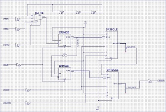
Here is the working version of the serial->parallel converter:
- 3.5 inch TFT serial to parallel converter.jpg (135.46 KiB) Viewed 1047 times
Its a shame no one makes a cheap board with the XC9536XL on it, as for most people is not practical to solder SMD
PS.
What does the part of the circuit with 3 inverters in series do ?
Perhaps we should start another thread for this FPGA / CPLD stuff.
Just wanted to show 2 pics, how easy is to make the board run at 36MHz.

- 20170111_211409_1.jpg (159.92 KiB) Viewed 1037 times
Of course, you may overclock the SPI and achieve higher speeds, but you take your chances then…
Looks good. Things are often not to difficult to implement once you have worked out what to do. However its the R&D to work out what to do thats the difficult and time consuming thing.
@Squonk42
Luckily the STM32 SPI speed (and most other parts of the MCU) are operate well beyond its published spec.
Virtually everyone using the ILI9341 display (probably 100+ people) run the SPI at 36Mhz with no problem at all.
I’ve even accidental run the whole MCU on 5V for several days and it didn’t do it any harm !
The general consensus is that the STM32F103 is pretty robust ![]()
I have realized one additional issue with using DMA: it is sharing the same data bus to memory with the CPU, so if the CPU has many memory accesses while DMA is running in the background, the CPU is then slowed down by DMA.
I am still thinking where should the SPI initialization take place: outside the ILI9486 driver, in setup phase, before or within the driver begin() function?
@Squonk42
Regarding SPI speed, I don’t know where you get the information from about the max. 18 MHz.
On page 691 of the RM0008 is written:
” 8 master mode baud rate prescalers (fPCLK/2 max.)”
Meaning, if fPCLK is 72 MHz, which is a “normal” frequency, then obviously we are talking about 36MHz “normal” SPI_1 speed. The max. 18 MHz is valid for SPI_2 only.
Of course, with overclocking one can achieve even higher speeds, which are then outside of specification, but still working, as Roger talked about the robustness of the chip.
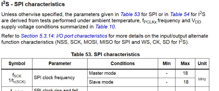
- SPI 103.JPG (83.85 KiB) Viewed 988 times
So, am I wrongly interpreting RM0008 or the datasheets are containing contradictory information?
But if I am not wrong, the 18 MHz limit is valid only for the I2S SPI frequency, not the “general” SPI frequency…
I am still thinking where should the SPI initialization take place: outside the ILI9486 driver, in setup phase, before or within the driver begin() function?
I’ve been working on a similar project on a Teensy platform, saw your code and thought I’d try it out on an STM32. The board (a Maple Mini clone) arrived yesterday, so I fired it up following Roger’s instructions on the Wiki and YouTube (very useful). No problems with LED blink, etc, so I think I have the tool-chain sorted for the STM.
Compiling the code from github produces some errors (not a problem), but one of them is the following – which is an apparent mismatch with SPI.cpp in hardware\Arduino_STM32\STM32F1\libraries\SPI\src.
Your code, below, seems to be writing a single value multiple times. This makes sense for drawing lines, etc of a single colour, but doesn’t match with the SPI write() function call.
The two-argument SPI write() function expects the first argument of be a pointer to an array of items to be written, not just a single item. (void SPIClass::write(const uint8 *data, uint32 length).
Can you give me any clues about where I might have gone wrong, or if you have made any improvements since you uploaded these files to github?
I’ll continue to debug while awaiting a response, as it’s more than likely the problem is between my chair and keyboard!
Richard
——————-
Adafruit_ILI9486_STM32.cpp
void writedata16(uint16_t color, uint32_t num)
{
SPI.setDataSize(DATA_SIZE_16BIT);
CD_DATA;
CS_ACTIVE;
//#ifdef USE_DMA
if (useDMA) {
lineBuffer[0] = color;
while (num>0xFFFF) {
SPI.dmaSend(lineBuffer, 0xFFFF, 0);
num -= 0xFFFF;
}
SPI.dmaSend(lineBuffer, num, 0);
//#else
} else {
SPI.write(color, num);
//#endif
}
CS_IDLE;
SPI.setDataSize(DATA_SIZE_8BIT);
}
——————————-
SPI.cpp
void writedata16(uint16_t color, uint32_t num)
{
SPI.setDataSize(DATA_SIZE_16BIT);
CD_DATA;
CS_ACTIVE;
//#ifdef USE_DMA
if (useDMA) {
lineBuffer[0] = color;
while (num>0xFFFF) {
SPI.dmaSend(lineBuffer, 0xFFFF, 0);
num -= 0xFFFF;
}
SPI.dmaSend(lineBuffer, num, 0);
//#else
} else {
SPI.write(color, num);
//#endif
}
CS_IDLE;
SPI.setDataSize(DATA_SIZE_8BIT);
}
If you have problems, please post the compiler generated error.
It seems that you pasted wrong info for the second function.
Extract from SPI.h:
    /**

* @brief Transmit one byte/word a specified number of times.

* @param data to transmit.

*/

void write(uint16 data, uint32 n);
/**

* @brief Transmit multiple bytes/words.

* @param buffer Bytes/words to transmit.

* @param length Number of bytes/words in buffer to transmit.

*/

void write(const void * buffer, uint32 length);
This is one of the functions which makes the DMA almost obsolete as there is no spi clock gaps between consecutive data, all continuous, for 16 bit data at least.
This is the function which makes the DMA almost obsolete, for 16 bit data at least.
But i will remind you now that you asked.
Thanks for the rapid response.
The core of the issue (apart from my mis-paste from the core SPI library) seems to be that I was using the SPI library from Roger’s master repo, rather than Steve’s amended one.
I will seek the revised one on Steve’s repo and use that in the interim, while the PR is pending.
I’m in no rush!
Richard
Works just fine with your modified SPI library.
Thanks
Benchmarks on my Maple Mini clone (2 button, Chinese) confirm yours.
Richard
After 15 years I am back to my old hobby. Well I am working on a smart home system based on CAN-BUS communication. I have chosen the STM32f103 to work with.
I have read this post a while ago and decided to buy the mentioned TFT display ( 3,5″ TFT-LCD Touch-Screen Display for Raspberry Pi):
http://www.ebay.de/itm/-/252472008067?
I have wired the Display to communicate with SPI 1 with the following configuration pins:
#define TFT_CNTRL GPIOA
#define TFT_RST PA3
#define TFT_RS PA2
#define TFT_CS PA4
I have used the SPI example in the STM32 library to test the SPI communication and the display responds always with the pattern 0x55, does it mean the communication is OK? I have disconnected it and I have got 0xFF!!! Looked fine to me!!
Well! Afterwards I could run the ILI9486 example program and got the run times statistic quite similar to the one in beginning of this post (see below!)
The problem is, that the display is just flashing white synchronously to the test sequences. After doing some debugging with Atollic , I could not detect any error.
Now I have no clue ![]() , why the display is not showing the test patterns!!!
, why the display is not showing the test patterns!!!
Can anybody give me a hint please!
(Sorry for my school English ![]() )
)
***** ILI9486 graphic Test *****
************************************************
Without DMA:
************************************************
Benchmark Time (microseconds)
Screen fill 356406
Text 50544
Lines 547817
Horiz/Vert Lines 31755
Rectangles (outline) 19880
Rectangles (filled) 869491
Circles (filled) 302401
Circles (outline) 435629
Triangles (outline) 112165
Triangles (filled) 356495
Rounded rects (outline) 132816
Rounded rects (filled) 997862
Done!
************************************************
Now using DMA:
************************************************
Benchmark Time (microseconds)
Screen fill 341522
Text 52901
Lines 622749
Horiz/Vert Lines 31425
Rectangles (outline) 20386
Rectangles (filled) 833499
Circles (filled) 359237
Circles (outline) 435628
Triangles (outline) 138814
Triangles (filled) 374145
Rounded rects (outline) 133456
Rounded rects (filled) 975637
Done!
Although the controller interface is SPI, but the display board contains a serial->parallel converter which is write-only.
Hence, these modules cannot be read, so the controller cannot be determined 100% sure, it may have other driver than ILI9486.
Still, I would suggest to lower the SPI clock speed down to 18MHz.
36MHz is only possible with the hardware-hack I posted here.
I have done the adjustment of the SPI clock down to 18MHz:
//SPI.beginTransaction(TFT_CS, SPISettings(36000000));
SPI.beginTransaction(TFT_CS, SPISettings(18000000));
The modification, as expected, slowed down the test:
************************************************
Without DMA:
************************************************
Benchmark Time (microseconds)
Screen fill 683415
Text 56114
Lines 609680
Horiz/Vert Lines 58171
Rectangles (outline) 34479
Rectangles (filled) 1666679
Circles (filled) 386663
Circles (outline) 477277
Triangles (outline) 126756
Triangles (filled) 591264
Rounded rects (outline) 155133
Rounded rects (filled) 1859289
Done!
Nevertheless the test pattern did show up on the screen an the flashing is the same as before ![]()
I have rechecked the wiring and it seems to be right.
Is the TFT display damaged? Do you have another hint?
You should somehow figure out which kind of controller it can be, and then use the appropriate init sequence to initialize it.
Additionally, you could go lower with the speed (4MHz), or even 1MHz. If the display is still flashing, then it must be a different controller.
In this case I cannot do much.
I would recommend to check different init sequences for different controllers (ILI9481, HX8375D, etc) available for example here. This was my source of inspiration, too.
init=-1,0xb0,0x0,-1,0x11,-2,250,-1,0x3A,0x55,-1,0xC2,0x44,-1,0xC5,0x00,0x00,0x00,0x00,-1,0xE0,0x0F,0x1F,0x1C,0x0C,0x0F,0x08,0x48,0x98,0x37,0x0A,0x13,0x04,0x11,0x0D,0x00,-1,0xE1,0x0F,0x32,0x2E,0x0B,0x0D,0x05,0x47,0x75,0x37,0x06,0x10,0x03,0x24,0x20,0x00,-1,0xE2,0x0F,0x32,0x2E,0x0B,0x0D,0x05,0x47,0x75,0x37,0x06,0x10,0x03,0x24,0x20,0x00,-1,0x36,0x28,-1,0x11,-1,0x29,-3If your init-sequence parser routine doesn’t handle DELAY lines, then the last few commands will need to be executed in the mainline code.
There are a few commented out lines in the middle, which were inherited from the RPi code. I haven’t tested them. The entire code is on github: https://github.com/palmerr23/STM32F01-I … RPi-Driver
I hope it helps.
Richard
const uint8_t ili9486_init_sequence[] =

{

//	2, 0xb0, 0x0,	// Interface Mode Control

//	1, 0x11,		// Sleep OUT

//	DELAY, 150,

2, 0x3A, 0x55,	// use 16 bits per pixel color

2, 0x36, 0x48,	// MX, BGR == rotation 0

//	2, 0xC2, 0x44,	// Power Control 3

// VCOM Control 1

//	5, 0xC5, 0x00, 0x00, 0x00, 0x00,

// PGAMCTRL(Positive Gamma Control)

16, 0xE0, 0x0F, 0x1F, 0x1C, 0x0C, 0x0F, 0x08, 0x48, 0x98,

0x37, 0x0A, 0x13, 0x04, 0x11, 0x0D, 0x00,

// NGAMCTRL(Negative Gamma Control)

16, 0xE1, 0x0F, 0x32, 0x2E, 0x0B, 0x0D, 0x05, 0x47, 0x75,

0x37, 0x06, 0x10, 0x03, 0x24, 0x20, 0x00,

// Digital Gamma Control 1

16, 0xE2, 0x0F, 0x32, 0x2E, 0x0B, 0x0D, 0x05, 0x47, 0x75,

0x37, 0x06, 0x10, 0x03, 0x24, 0x20, 0x00,

1, 0x11,	// Sleep OUT

DELAY, 150, 	// wait some time

1, 0x29,	// Display ON

0			// end marker

};
Did this code work on your STM32F103?
I have followed all the hints above, but I could not run any demo on this display. The device I have bought looks exactly the same as yours at the beginning of this post. I have tried your example with no positive results. Obviously there is a serial parallel converter on the board, that why it is a write only device. I have tried ILI9481 and ILI9486 . If the controller is not ILI9486, what might it be?
I will be thankful for any hint!

- Pinout RPi Display.jpg (106.42 KiB) Viewed 1679 times
Pick a “fb_*.c” file and extract the init sequence, replace the version from my lib with that one and build the project.
If it does not seem to work, take the next .c file.
Sorry, but this “trial and error” method seems the only way to figure out the real controller.
Additional init sequences you can find in David’s repo: https://github.com/prenticedavid/MCUFRI … ND_kbv.cpp, starting with line 824.
I maybe not mentioned before, but you should double check the connections, and be sure that the GPIOs toggle.
As Steve said, with a write-only display you can only use guesswork.
Most 320×480 controllers are MIPI compliant. And probably start up by themselves. Just Reset, Display Off, Wake up, Display On. (with some pauses)
Two typical Register arrangements:
ILI9481 with Power/VCOM in regs 0xD0..
ILI9486 with Power/VCOM in regs 0xC0..
Once you have determined which group, you can do some diagnosis by writing bits in Panel Control Registers, …
Different Manufacturers have subtle differences.
It is important to know what controller is mounted.
David.
good news, bad news
good – not much, you can find the pinning details for the socket
bad – couldn’t see / find a schematic – rather surprised, but given the following lines perhaps understandable
bad – some cloning of their products
bad – yours doesn’t seem to match their picture
bad – doesn’t seem to match the fakes
i suspect the easiest is to find a Raspberry Pi and if there’s anything in the driver or boot messages.
stephen
You can always ask WaveShare for the schematic. Or simply work it out by yourself.
I do not own a RaspPi. I know nothing about them.
David.
I will work through your hints. Hopefully one of them would work.
Finally I have got it done! I have found out the right initialisation sequence. The SPI frequency is crucial. The display works only in the range between 12MHz and 32MHz only. Any frequency out of this range lead to white flashing on the screen!
– The described pin out of the display on the site of the vender was wrong
– The Init sequence had to be changed slightly ( I have got the right sequence of the init sequence of a raspberry pi, which was posted in the internet)
– The frequency e.g. 8MHz does not work. I could not understand till now, why lower frequencies did not work
After I have found out, that the pin out description was wrong, I managed to solve the problem very fast.
Thanks to all for the support!
If you might be interested, here is the right pin out of the display I am using (http://www.ebay.de/itm/252472008067?ul_noapp=true):
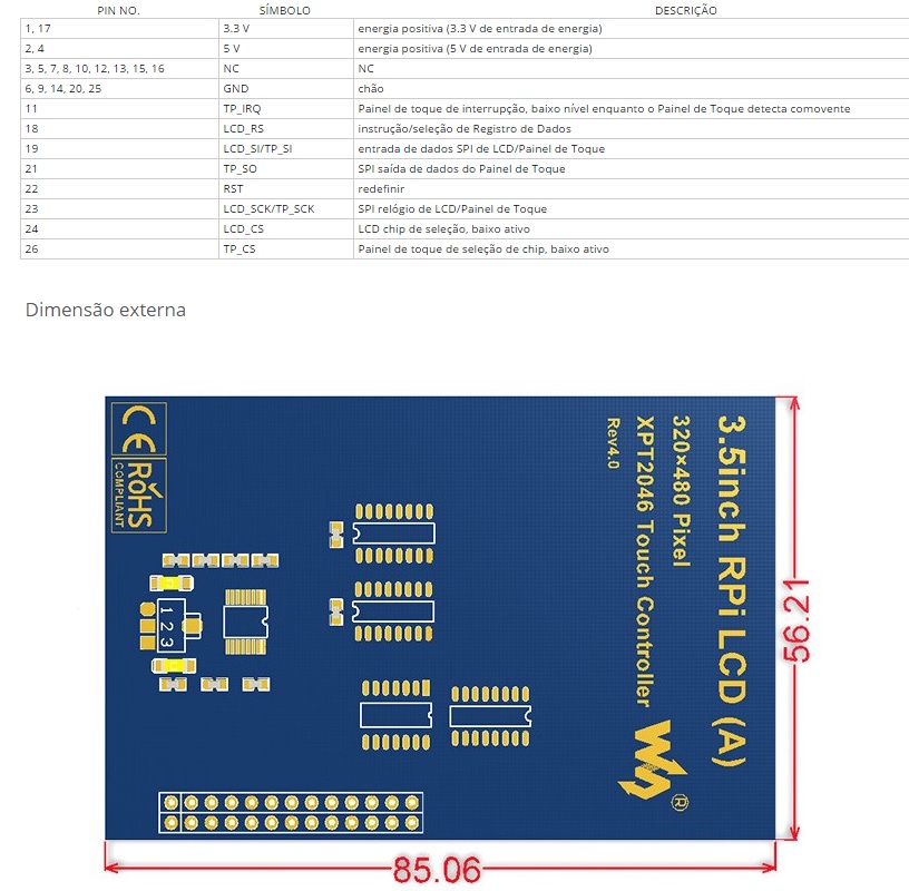
- 35Inch Display Pinout.jpg (163.87 KiB) Viewed 2345 times
I modified my ILI9486 – SPI board for 16bit parallel access. The reason was to obtain higher write speed.
The files can be found here: https://github.com/stevstrong/Adafruit_ … 6bit_STM32
I tested it with my black F4 board.
The current benchmark:
Benchmark                Time (microseconds)

Screen fill              104767

Text                     10386

Lines                    185635

Horiz/Vert Lines         9400

Rectangles (outline)     5971

Rectangles (filled)      255546

Circles (filled)         95452

Circles (outline)        78896

Triangles (outline)      51741

Triangles (filled)       112147

Rounded rects (outline)  26409

Rounded rects (filled)   295197
Here the bench using FSMC:
Benchmark                Time (microseconds)

Screen fill              48091

Text                     5683

Lines                    83850

Horiz/Vert Lines         4258

Rectangles (outline)     2655

Rectangles (filled)      117322

Circles (filled)         39360

Circles (outline)        35190

Triangles (outline)      23373

Triangles (filled)       50048

Rounded rects (outline)  12160

Rounded rects (filled)   134562
I modified my ILI9486 – SPI board for 16bit parallel access. The reason was to obtain higher write speed.
The files can be found here: https://github.com/stevstrong/Adafruit_ … 6bit_STM32
I tested it with my black F4 board.
The current benchmark:
Benchmark                Time (microseconds)

Screen fill              104767

Text                     10386

Lines                    185635

Horiz/Vert Lines         9400

Rectangles (outline)     5971

Rectangles (filled)      255546

Circles (filled)         95452

Circles (outline)        78896

Triangles (outline)      51741

Triangles (filled)       112147

Rounded rects (outline)  26409

Rounded rects (filled)   295197
Which pins do you use for the data bus?
I see that it has 8 bit bus, so you should could use the 8 bit parallel library.
Your photo shows a paper sticker “4535”. This implies an LGDP4535 controller but you can never trust Ebay. (I have one with “9488” label and it contains a HX8357-D)
Please install/update your MCUFRIEND_kbv library with the Library Manager.
Most examples report the ID to the Serial Terminal.
If still unknown, run the LCD_ID_readreg sketch and paste the output to the Arduino Forum in the “Displays” section.
I don’t mind answering an STM32 question here. The Arduino Forum reaches more people.
Incidentally, the LGDP4535 is supported out of the box. The LGDP4532 requires enabling the SUPPORT_4532 define.
Where did you get this idea:
if (identifier == 0xEFEF) identifier = 0x9486;
And paste here the result from the serial monitor.
#define LCD_RST PB0

#define LCD_CS PA3

#define LCD_RS PA2

#define LCD_WR PA1

#define LCD_RD PA0
#define LCD_D0 PA8
#define LCD_D1 PA9
#define LCD_D2 PA10
#define LCD_D3 PA11
#define LCD_D4 PA12
#define LCD_D5 PA13
#define LCD_D6 PA14
#define LCD_D7 PA15
After run the LCD_ID_readreg.ino adapted acording to the lasts posts, serial monitor show me this:
Read Registers on MCUFRIEND UNO shield

controllers either read as single 16-bit

e.g. the ID is at readReg(0)

or as a sequence of 8-bit values

in special locations (first is dummy)
reg(0x0000) 00 00 ID: ILI9320, ILI9325, ILI9335, ...
reg(0x0004) 04 04 04 04 Manufacturer ID
reg(0x0009) 09 09 09 09 09 Status Register
reg(0x000A) 0A 0A Get Powsr Mode
reg(0x000C) 0C 0C Get Pixel Format
reg(0x0061) 61 61 RDID1 HX8347-G
reg(0x0062) 62 62 RDID2 HX8347-G
reg(0x0063) 63 63 RDID3 HX8347-G
reg(0x0064) 64 64 RDID1 HX8347-A
reg(0x0065) 65 65 RDID2 HX8347-A
reg(0x0066) 66 66 RDID3 HX8347-A
reg(0x0067) 67 67 RDID Himax HX8347-A
reg(0x0070) 70 70 Panel Himax HX8347-A
reg(0x00A1) A1 A1 A1 A1 A1 RD_DDB SSD1963
reg(0x00B0) B0 B0 RGB Interface Signal Control
reg(0x00B4) B4 B4 Inversion Control
reg(0x00B6) B6 B6 B6 B6 B6 Display Control
reg(0x00B7) B7 B7 Entry Mode Set
reg(0x00BF) BF BF BF BF BF BF ILI9481, HX8357-B
reg(0x00C0) C0 C0 C0 C0 C0 C0 C0 C0 C0 Panel Control
reg(0x00C8) C8 C8 C8 C8 C8 C8 C8 C8 C8 C8 C8 C8 C8 GAMMA
reg(0x00CC) CC CC Panel Control
reg(0x00D0) D0 D0 D0 Power Control
reg(0x00D2) D2 D2 D2 D2 D2 NVM Read
reg(0x00D3) D3 D3 D3 D3 ILI9341, ILI9488
reg(0x00DA) DA DA RDID1
reg(0x00DB) DB DB RDID2
reg(0x00DC) DC DC RDID3
reg(0x00E0) E0 E0 E0 E0 E0 E0 E0 E0 E0 E0 E0 E0 E0 E0 E0 E0 GAMMA-P
reg(0x00E1) E1 E1 E1 E1 E1 E1 E1 E1 E1 E1 E1 E1 E1 E1 E1 E1 GAMMA-N
reg(0x00EF) EF EF EF EF EF EF ILI9327
reg(0x00F2) F2 F2 F2 F2 F2 F2 F2 F2 F2 F2 F2 F2 Adjust Control 2
reg(0x00F6) F6 F6 F6 F6 Interface Control
You do realise that you could simply plug the Shield into a NUCLEO-F103, NUCLEO-L476, IteadMaple or efftek’s Adapter. All of these work out of the box.
Since you have chosen to invent your own wiring, you have to check that it actually works.
Life is simpler if you copy some proven wiring e.g. efftek for a BluePill.
David.
I could not find any lib for this driver, however much I have researched. I tried using the https://github.com/stevstrong/Adafruit_ … 8bit_STM32 but I did not succeed either, even editing the files correctly to indicate the wiring of the data pins.
Is there a solution for using the Generic STM32F103C (Blue Pill) with this TFT display with “4535” driver?
#define USE_MAGFLIP
http://forum.arduino.cc/index.php?topic=314912.0
There is an attachment in the very first port of that thread.
It looks like it uses the ILI932x_regValues for the init sequence.
There are several versions of Adafruit_TFTLCD library that have been hacked for an LGDP4535. There are probably some original ones too. As far as I know, they will only run on a Uno or Mega.
The OP wants a library that works on his STM32 BluePill with his custom wiring.
David.
https://www.aliexpress.com/snapshot/0.h … 2707058182
cannot run the stm32f4discovery.
What is the minimum frequency of the spi can operate?
The spi mode only 16 bits???
What is the maximum length of the wires?
Which core are you using?
Maximum frequency is ~24MHz without my mod.
Yes, SPI is working in 16 bit mode.
Wires should be as short as possible.
Installed chip ILI9486?
If I understand correctly, limits the minimum frequency, no?
Is there any example of initializing the spi for the display?
Is it possible without initializing the display to send any sequence of commands, and see the screen change?
https://github.com/stevstrong/Arduino_S … generic_f4
together with this display lib
https://github.com/stevstrong/Adafruit_ILI9486_STM32
?
If yes, please detail what exactly is not working.
Unfortunately I don’t have any F4 discovery board, so I cannot test it on that board.
I have got this display running! Please refer to my post view pages ago.
I could send you my functioning exmaple, if you wish!
Best regards
[fari – Tue Jul 11, 2017 8:02 am] –
I have got this display running! Please refer to my post view pages ago.
I could send you my functioning exmaple, if you wish!
Hi fari and others,
I got the display a week ago and fail to power it on. I use this example https://github.com/stevstrong/Adafruit_ILI9486_STM32.
Could you help me with the wiring? I tried to connect follow the LCD pin out you posted.
[stevestrong – Sun May 21, 2017 3:48 pm] –
I would suggest to use the LCD reg test sketch from David, it helps to check your wiring.
And paste here the result from the serial monitor.
[stevestrong – Sun Jun 25, 2017 9:02 am] –
Aleksey, do you use this software
https://github.com/stevstrong/Arduino_S … generic_f4
together with this display lib
https://github.com/stevstrong/Adafruit_ILI9486_STM32
?
If yes, please detail what exactly is not working.
Unfortunately I don’t have any F4 discovery board, so I cannot test it on that board.
I know I am not supposed to bump an old thread – but since this covers exactly what I am trying to do, and has gotten me this far, it is probably the best place for this question.
Anyway, I have one of these generic 3.5inch RPi LCDs. The above library works perfectly for running the LCD. The XPT_2046 library also works perfectly for driving the touch panel. BUT the two do not work together. Display calls break the touch panel, and vice-versa.
The two functions share the SPI pins, but have a different CS line. A quick look at the code suggests that it is probably the single SPI transaction in the LCD driver at fault. Before I start making changes, I would like to verify the following:
1) my guess as to the cause is correct, and
2) no-one else is currently working on this.
If this is the case, then I am more than happy to add transaction support to the public API functions, and send patches.
Thanks,
Justin
So I cannot even test the lib any further on that display.
Anyway, any improvement you make is welcome.
In the ili9486 cpp file you’ll find many:
SPI.setDataSize(DATA_SIZE_16BIT);[madias – Thu May 31, 2018 10:18 pm] –
Maybe another thing:
In the ili9486 cpp file you’ll find many:
SPI.setDataSize(DATA_SIZE_16BIT);
- 16843.jpg (31.8 KiB) Viewed 614 times
[heisan – Fri Jun 01, 2018 7:01 pm] –
Confirmed – wrap the TFT code in startTransaction .. endTransaction and everything works perfectly.
Did you enabled DMA? With DMA I have some artefacts with the graphic tests (not only with this display) It’s on my todo list to investigate the problem (maybe too much speed for the controller).
Can you attach your code/library, so I do not have to reinvent (rewrite) the wheel? (#define lazymode) ![]()
Another thing:
I need to be free of choice of the DC,RST,CS…. pins, so I reversed this in the *.h file: (Better you use Pxx than “8” or “9” – it was a fast conversation of mine)
Define pins and Output Data Registers

*/
//Control pins |RS |CS |RST|
#define TFT_CNTRL GPIOA
#define TFT_RST 8
#define TFT_RS 9
#define TFT_CS 10
#define TFT_CS_MASK BIT4
#define TFT_RS_MASK BIT0
/*
extern gpio_reg_map *ctrlRegs;
#define CS_ACTIVE ctrlRegs->BRR = TFT_CS_MASK //digitalWrite(TFT_CS, LOW); //
#define CS_IDLE ctrlRegs->BSRR = TFT_CS_MASK //digitalWrite(TFT_CS, HIGH); //
#define CD_COMMAND ctrlRegs->BRR = TFT_RS_MASK //digitalWrite(TFT_RS, LOW); //
#define CD_DATA ctrlRegs->BSRR = TFT_RS_MASK //digitalWrite(TFT_RS, HIGH); //
*/
#define CS_ACTIVE digitalWrite(TFT_CS, LOW); //
#define CS_IDLE digitalWrite(TFT_CS, HIGH); //
#define CD_COMMAND digitalWrite(TFT_RS, LOW); //
#define CD_DATA digitalWrite(TFT_RS, HIGH); //
#define swap(a, b) { int16_t t = a; a = b; b = t; }
/*****************************************************************************/
diff -u ./Adafruit_ILI9486_STM32.cpp /home/justin/Arduino/libraries/Adafruit_ILI9486_STM32/Adafruit_ILI9486_STM32.cpp

--- ./Adafruit_ILI9486_STM32.cpp	2017-02-02 14:40:50.000000000 +0200

+++ /home/justin/Arduino/libraries/Adafruit_ILI9486_STM32/Adafruit_ILI9486_STM32.cpp	2018-06-01 21:37:20.659070014 +0200

@@ -12,7 +12,7 @@

/*****************************************************************************/

// Constructor uses hardware SPI, the pins being specific to each device

/*****************************************************************************/

-Adafruit_ILI9486_STM32::Adafruit_ILI9486_STM32(void) : Adafruit_GFX(TFTWIDTH, TFTHEIGHT){}

+Adafruit_ILI9486_STM32::Adafruit_ILI9486_STM32(void) : Adafruit_GFX(TFTWIDTH, TFTHEIGHT), spiSet(SPISettings(36000000)), _trans(0) {}

/*****************************************************************************/

void writedata16(uint16_t c)

{

@@ -117,6 +117,21 @@

}

}

/*****************************************************************************/

+void Adafruit_ILI9486_STM32::startSPI(void)

+{

+    if(_trans == 0)

+    	SPI.beginTransaction(TFT_CS, spiSet);

+    _trans++;

+}

+

+void Adafruit_ILI9486_STM32::endSPI(void)

+{

+    _trans--;

+    if(_trans == 0)

+    	SPI.endTransaction();

+    if(_trans < 0) _trans = 0; // sanity check if we end too many times, at least the next start will work...

+}

+

void Adafruit_ILI9486_STM32::begin(void)

{

ctrlRegs = TFT_CNTRL->regs;

@@ -137,14 +152,17 @@

digitalWrite(TFT_RST, HIGH);

delay(200);

}

-    SPI.beginTransaction(TFT_CS, SPISettings(36000000));

+	startSPI();

+    //SPI.beginTransaction(TFT_CS, SPISettings(36000000));

// init registers

commandList(ili9486_init_sequence);

useDMA = 0;

+	endSPI();

}

/*****************************************************************************/

void Adafruit_ILI9486_STM32::setAddrWindow(uint16_t x0, uint16_t y0, uint16_t x1, uint16_t y1)

{

+	startSPI();

writecommand(ILI9486_CASET); // Column addr set

writedata(x0 >> 8);

writedata(x0 & 0xFF);     // XSTART

@@ -158,19 +176,24 @@

writedata(y1);     // YEND
writecommand(ILI9486_RAMWR); // write to RAM
+ endSPI();
}
/*****************************************************************************/
void Adafruit_ILI9486_STM32::pushColor(uint16_t color)
{
+ startSPI();
writedata16(color);
+ endSPI();
}
/*****************************************************************************/
void Adafruit_ILI9486_STM32::drawPixel(int16_t x, int16_t y, uint16_t color)
{
if ((x < 0) || (x >= _width) || (y < 0) || (y >= _height)) return;
+ startSPI();
setAddrWindow(x, y, x + 1, y + 1);
pushColor(color);
+ endSPI();
}
/*****************************************************************************/
void Adafruit_ILI9486_STM32::drawFastVLine(int16_t x, int16_t y, int16_t h, uint16_t color)
@@ -178,10 +201,12 @@
// Rudimentary clipping
if ((x >= _width) || (y >= _height || h < 1)) return;
if ((y + h - 1) >= _height) { h = _height - y; }
- if (h < 2 ) { drawPixel(x, y, color); return; }
+ if (h < 2 ) { drawPixel(x, y, color); return; } // drawpixel already wrapped
+ startSPI();
setAddrWindow(x, y, x, y + h - 1);
writedata16(color, h);
+ endSPI();
}
/*****************************************************************************/
void Adafruit_ILI9486_STM32::drawFastHLine(int16_t x, int16_t y, int16_t w, uint16_t color)
@@ -189,17 +214,21 @@
// Rudimentary clipping
if ((x >= _width) || (y >= _height || w < 1)) return;
if ((x + w - 1) >= _width) { w = _width - x; }
- if (w < 2 ) { drawPixel(x, y, color); return; }
+ if (w < 2 ) { drawPixel(x, y, color); return; } // drawPixel already wrapped
+ startSPI();
setAddrWindow(x, y, x + w - 1, y);
writedata16(color, w);
+ endSPI();
}
/*****************************************************************************/
void Adafruit_ILI9486_STM32::fillScreen(uint16_t color)
{
+ startSPI();
setAddrWindow(0, 0, _width, _height);
writedata16(color, (_width*_height));
+ endSPI();
}
/*****************************************************************************/
@@ -210,12 +239,14 @@
if ((x + w - 1) >= _width) { w = _width - x; }
if ((y + h - 1) >= _height) { h = _height - y; }
if (w == 1 && h == 1) {
- drawPixel(x, y, color);
+ drawPixel(x, y, color); // already wrapped
return;
}
+ startSPI();
setAddrWindow(x, y, x + w - 1, y + h - 1);
writedata16(color, (w*h));
+ endSPI();
}
/*
@@ -336,6 +367,7 @@
/*****************************************************************************/
void Adafruit_ILI9486_STM32::setRotation(uint8_t m)
{
+ startSPI();
writecommand(ILI9486_MADCTL);
rotation = m & 3; // can't be higher than 3
switch (rotation) {
@@ -360,9 +392,12 @@
_height = TFTWIDTH;
break;
}
+ endSPI();
}
/*****************************************************************************/
void Adafruit_ILI9486_STM32::invertDisplay(boolean i)
{
+ startSPI();
writecommand(i ? ILI9486_INVON : ILI9486_INVOFF);
+ endSPI();
}
diff -u ./Adafruit_ILI9486_STM32.h /home/justin/Arduino/libraries/Adafruit_ILI9486_STM32/Adafruit_ILI9486_STM32.h
--- ./Adafruit_ILI9486_STM32.h 2017-02-02 14:40:50.000000000 +0200
+++ /home/justin/Arduino/libraries/Adafruit_ILI9486_STM32/Adafruit_ILI9486_STM32.h 2018-06-01 21:42:04.965356555 +0200
@@ -80,6 +80,8 @@
Adafruit_ILI9486_STM32(void);
void begin(void),
+ startSPI(void), // these two are public - if you are going to do a bunch of consecutive display calls
+ endSPI(void), // wrap them in a startSPI..endSPI pair, so that each individual function does not do the same
setAddrWindow(uint16_t x0, uint16_t y0, uint16_t x1, uint16_t y1),
pushColor(uint16_t color),
fillScreen(uint16_t color),
@@ -95,7 +97,8 @@
void reset(void);
private:
- uint8_t tabcolor;
+ SPISettings spiSet;
+ int _trans;
};
void writecommand(uint8_t c),
writedata(uint8_t d),
Common subdirectories: ./examples and /home/justin/Arduino/libraries/Adafruit_ILI9486_STM32/examples
PS. No DMA corruption on my side – but also no real speed up, except on screen fills.
But: still graphic errors: You can see them clearly on:
the last green rounded rectangle (and other gradient filled rectanges/triangles but you have to look very closely)
They should have a nice color gradient.
See the compares (I used the teensy (but also on maple mini! ) library for the second one (without DMA) which is based on Steves code):
actual one:
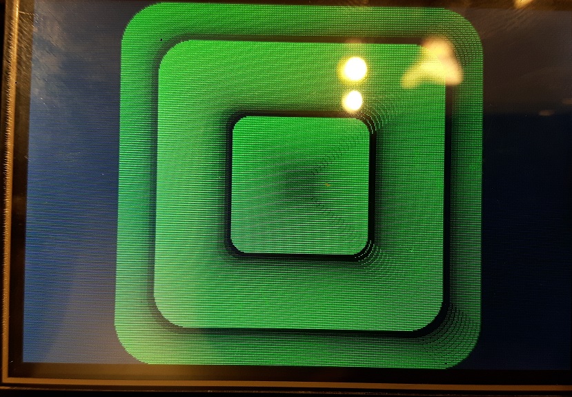
Teensy one (sorry, a little bit blured):
You can try the teensy library here, but you must change the pins within *.h:
https://github.com/palmerr23/ILI9486_Teensy_Library
[madias – Fri Jun 01, 2018 10:58 pm] –
But: still graphic errors: You can see them clearly on:
the last green rounded rectangle (and other gradient filled rectanges/triangles but you have to look very closely)
They should have a nice color gradient.
I think that is sw error, but not 100% sure.
[stevestrong – Sat Jun 02, 2018 7:11 am] –
I think that is sw error, but not 100% sure.
The teensy library is based on your code – without errors.
But it’s not a DMA problem (even with DMA disabled -> same errors).
The teensy library is MUCH slower – maybe the errors caused by to high speed (SPI or low level pin manipulations) – It should be not to difficult to find the problem as we have two – almost same – libraries
#define CS_ACTIVE    ctrlRegs->BRR  = TFT_CS_MASK //digitalWrite(TFT_CS, LOW); //

#define CS_IDLE      ctrlRegs->BSRR = TFT_CS_MASK //digitalWrite(TFT_CS, HIGH); //

#define CD_COMMAND   ctrlRegs->BRR  = TFT_RS_MASK //digitalWrite(TFT_RS, LOW); //

#define CD_DATA ctrlRegs->BSRR = TFT_RS_MASK //digitalWrite(TFT_RS, HIGH); //Was the same sketch?
[stevestrong – Sat Jun 02, 2018 7:50 am] –
Sorry not being clear, I meant the graphicstest sketch.
Was the same sketch?
It’s the same sketch. I just used the teensy graphictest and only replaced the library.
changed the SPI speed to :
Adafruit_ILI9486_STM32::Adafruit_ILI9486_STM32(void) : Adafruit_GFX(TFTWIDTH, TFTHEIGHT), spiSet(SPISettings(24000000)), _trans(0) {}
