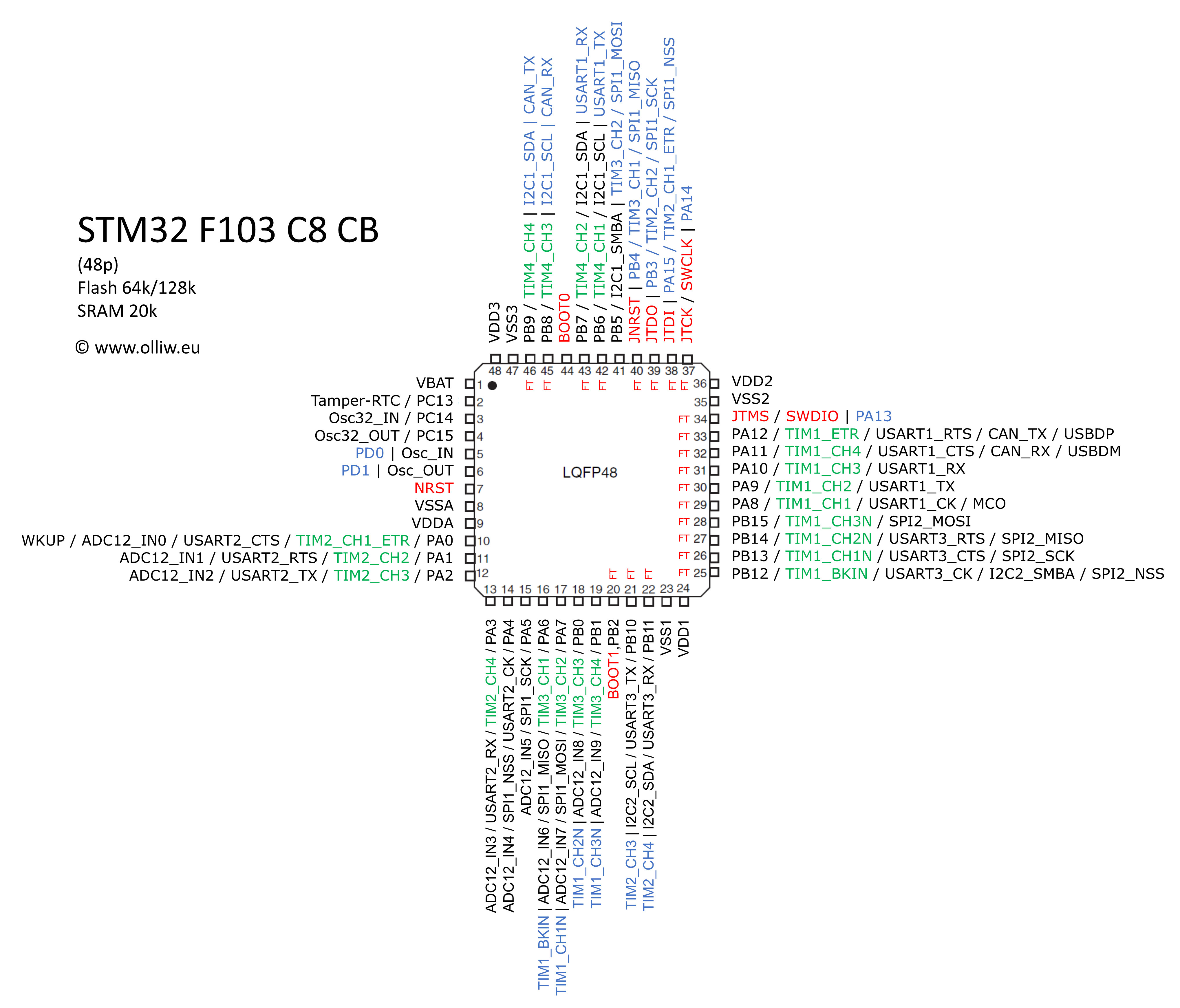
Did someone already a pinout picture for the chip with its capability(i2c, spi, pwm etc)?
For this board(or generally the chip itself):
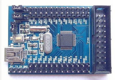
Thanks for help ![]()
~Straw
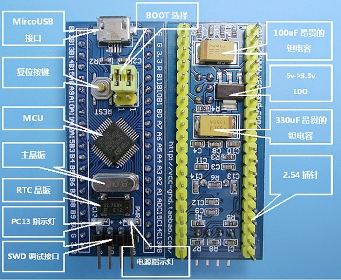
The pinout is basically same as the Maple mini
I’ll try to convert the table from that page int something that can be used in a sticky on the forum, but is a bit complicated as I have to convert all the tags
http://leaflabs.com/docs/hardware/maple-mini.html
This may work, or it may come out as gibberish ![]()
Pin		GPIO		ADC		Timer		I2C		UART		SPI		5 V?

D0		PB11		*		*			2_SDA	3_RX			*		Yes

D1		PB10		*		*			2_SCL	3_TX			*		Yes

D2		PB2		*		*			*		*			*		Yes

D3		PB0		CH8		3_CH3		*		*			*		*

D4		PA7		CH7		3_CH2		*		*			1_MOSI	*

D5		PA6		CH6		3_CH1		*		*			1_MISO	*

D6		PA5		CH5		*			*		*			1_SCK	*

D7		PA4		CH4		*			*		2_CK			1_NSS	*

D8		PA3		CH3		2_CH4		*		2_RX			*		*

D9		PA2		CH2		2_CH3		*		2_TX			*		*

D10		PA1		CH1		2_CH2		*		2_RTS		*		*

D11		PA0		CH0		2_CH1_ETR	*		2_CTS		*		*

D12		PC15		*		*			*		*			*		*

D13		PC14		*		*			*		*			*		*

D14		PC13		*		*			*		*			*		*

D15		PB7		*		4_CH2		1_SDA	*			*		Yes

D16		PB6		*		4_CH1		2_SCL	*			*		Yes

D17		PB5		*		*			1_SMBA	*			*		*

D18		PB4		*		*			*		*			*		Yes

D19		PB3		*		*			*		*			*		Yes

D20		PA15		*		*			*		*			*		Yes

D21		PA14		*		*			*		*			*		Yes

D22		PA13		*		*			*		*			*		Yes

D23		PA12		*		1_ETR		*		1_RTS		*		Yes

D24		PA11		*		1_CH4		*		1_CTS		*		Yes

D25		PA10		*		1_CH3		*		1_RX			*		Yes

D26		PA9		*		1_CH2		*		1_TX			*		Yes

D27		PA8		*		1_CH1		*		1_CK			*		Yes

D28		PB15		*		*			*		*			2_MOSI	Yes

D29		PB14		*		*			*		3_RTS		2_MISO	Yes

D30		PB13		*		*			*		3_CTS		2_SCK	Yes

D31		PB12		*		1_BKIN		2_SMBA	3_CK			2_NSS	Yes

D32		PB8		*		4_CH3		*		*			*		Yes
Gonna try to make some Pictures with the io-pins, bit in the style of those arduino pinout pictures ^^
~Straw
…or this…
I’ll try to convert the table from that page int something that can be used in a sticky on the forum, but is a bit complicated as I have to convert all the tags
I’ll try to convert the table from that page int something that can be used in a sticky on the forum, but is a bit complicated as I have to convert all the tags
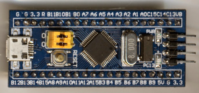
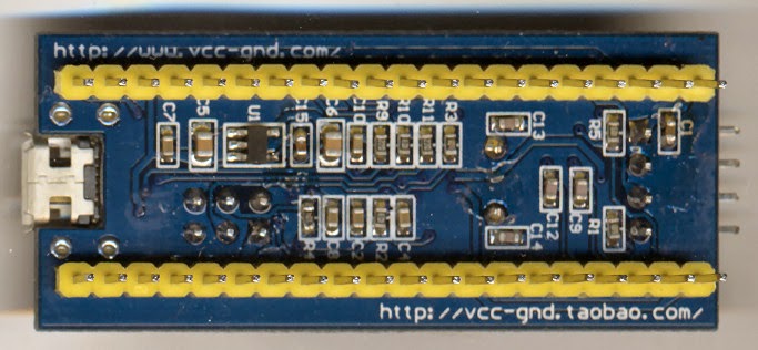
I believe that there are other versions of this cheap board.
Some has bigger LDO and capacitors underneath
others stlink pins doesn’t cover the pin writing like in mine.
~Straw

Nice little board (40 x 50mm) with 80 GPIO + microSD + 1KB EEPROM + 32kHz Xtal
http://www.ebay.com/itm/1PCS-STM32F103V … 1433302819
Edit
LED:
PB9
EEPROM:
PB6 – SCL
PB7 – SDA
Addr: 0x50, 0x51, 0x52, 0x53
SD 4 bit mode: (edited)
1 – PC10 – DAT2 – SDIO_D2
2 – PC11 – DAT3 – SDIO_D3
3 – PD2 – CMD – SDIO_CMD
4 – VDD
5 – PC12 – CLK – SDIO_CK
6 – VSS
7 – PC8 – DAT0 – SDIO_D0
8 – PC9 – DAT1 – SDIO_D1
PA8 – Card Detect
Just ordered one on eBay $13 ($17 AU)
80 GPIO ought to be enough for anybody
Actually, I already have a STM32F103ZET board
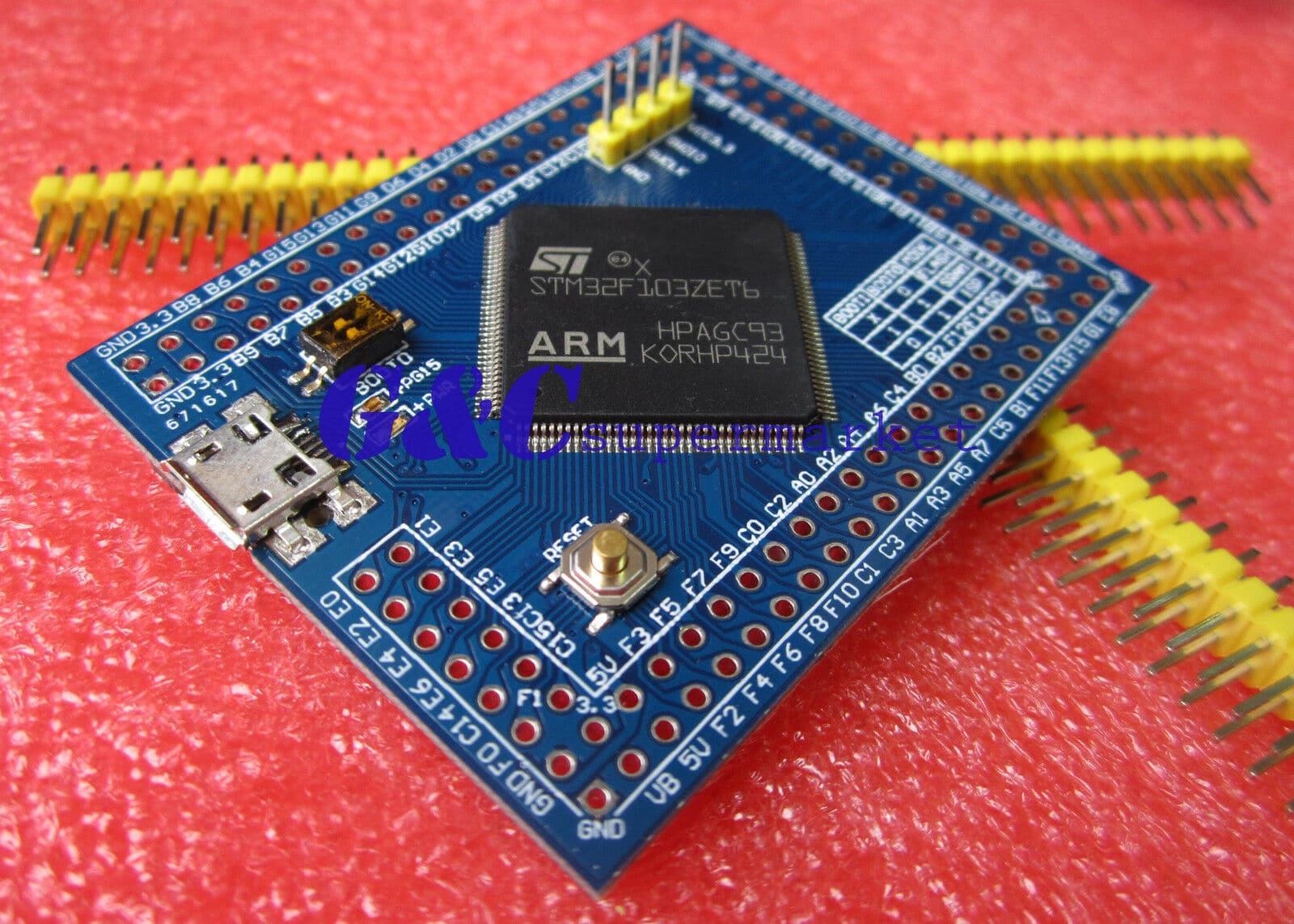
which has 112 pins, and I actually quite like it. But soldering all 112 pins on, did take some time
I have this too, but how often du you need 112 GPIO?
![]()
Maybe i can help with this work, im not good with drawing, but if you need help for something like to read the datasheet and put the pinout with default and alternate functions on csv or an excel sheet, just tell me.
I have 2 different boards, the first is the same board with yellow jumpers and headers that zoomx has. The other type I own comes with an STM32F103VET6, 2 mini usb (one has an USB to RS232 ic), slot for the RTC backup battery and other things:
Front:

Back:
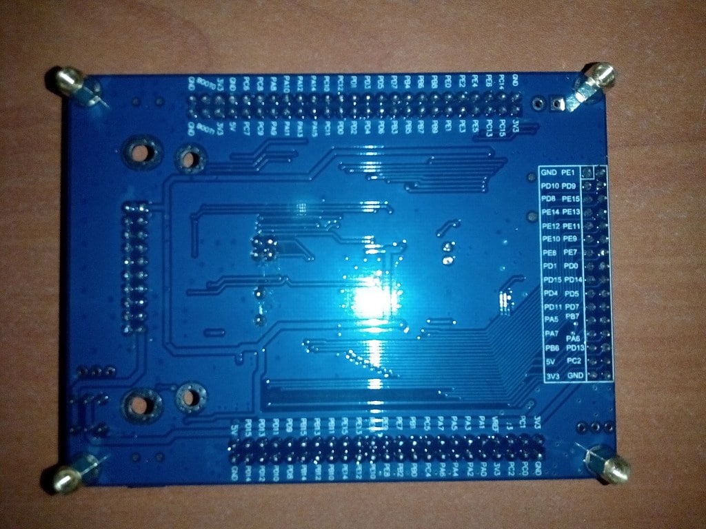
Sorry for the quality of the pictures, taken with a bad cellphone camera and bad lightning conditions. I will update tomorrow with better pictures
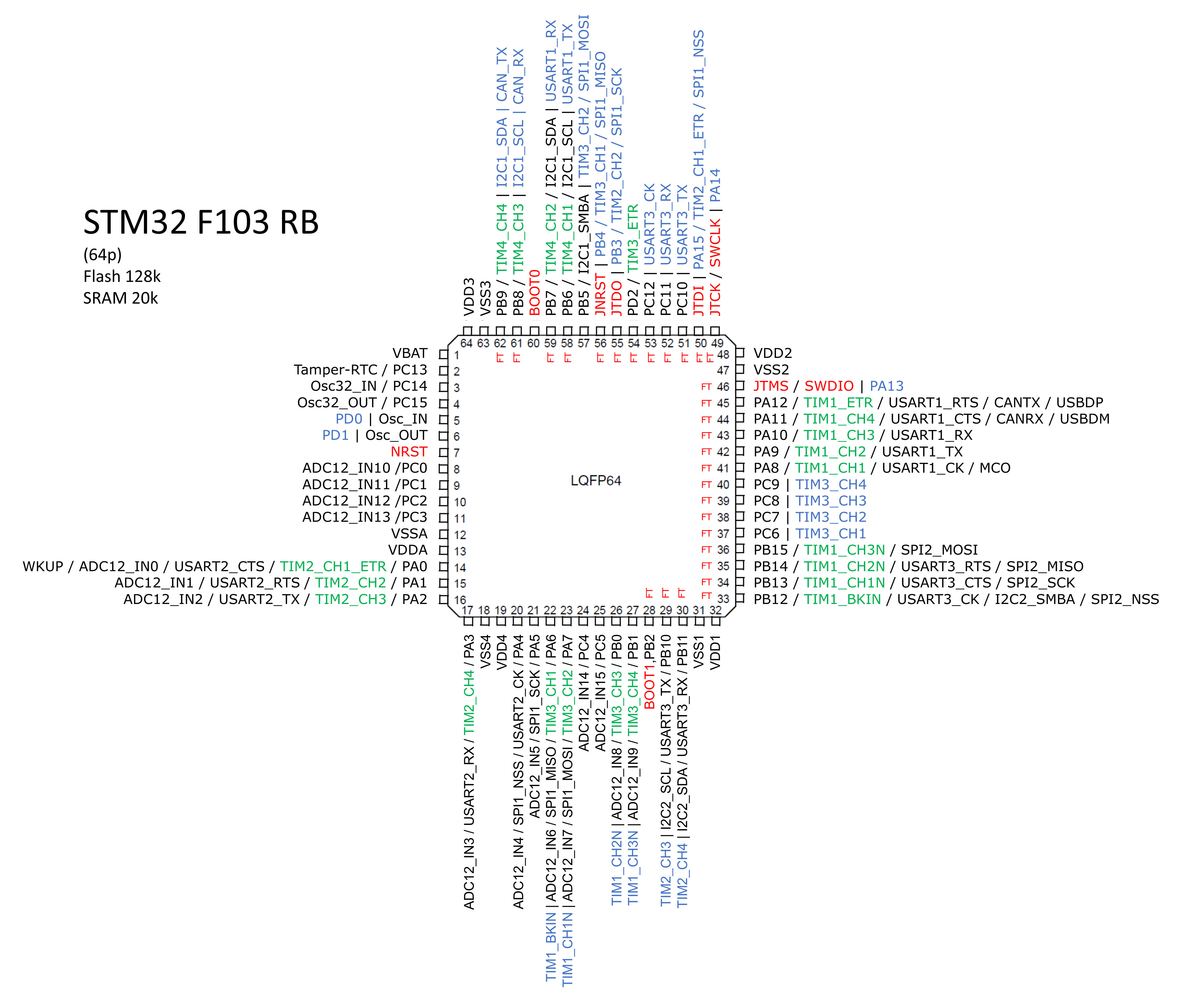
Use the STM32F103Z board type for that board. It defined more GPIO than you have, but I don’t think it makes any difference ![]()
I have order a V series board, so I’ll do a generic board definition for it when it arrives. as its basically just the Z board with some gpio removed
I just posted this on another thread, but this one seems more appropriate. I’ve been working on a C# program to generate pin maps, here are a couple I have done:
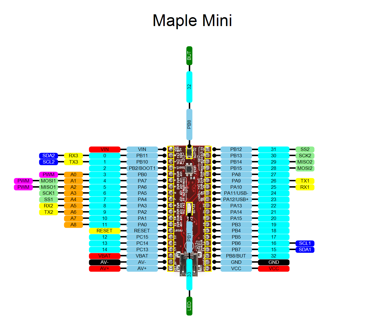
- Maple Mini.png (232.4 KiB) Viewed 4253 times
Where else did you post it ?
I’m not sure if it would clutter up the diagram, but having something to indicate if a pin was 5V tolerant would also be beneficial
Are you going to post your C# code ?
Thanks
Roger
viewtopic.php?f=29&t=93
If someone is interested I can give you the original xls sheet – it’s quiet easy to adapt it for another board.
Refering the bluepillpinout pic I miss the ARDUINO pins, A0…AN and D0…Dn.
In STM32 mini pic (red pill) I only found the analog pins.
BTW.. The “Morpho” Connector on (X)Nucleo-F103 board contains the signals PC4, PF4 and PF5 but they are not listed in corresponding board.h.enum
