I’m gearing up to produce some SMD boards, and would be interested to get any recommendations of where to get solder paste.
I bought some from AliExpress a while ago, but I cant track down its chemical tin to lead ratio.
I’m going to buy some paste locally, but at $12 for 15g, I suspect that I can get a better deal online at AliExpress.
However I’m not sure if any of the paste on AliExpress is any good.
http://www.ebay.com/sch/i.html?_from=R4 … te&_sop=15
It is very easy to use, the only downside is the lead content (so not ROHS compliant), personally I’ve probably absorbed far too much lead over the years to start worrying now, and of course slowboat wait.
I have no particular seller to recommend, since I haven’t bought any recently, but I suspect they are one as good as the other, and since you are only risking a couple of dollars, and are protected by Ebay/Paypal I wouldn’t loose too much sleep over this sort of transaction going pearshaped.
Fortunately, by chance, it took only 3 weeks.
Unfortunately, the board I wish to try it on is not arrived yet.
I’m going to get some paste locally this morning from Jaycar, but its far more expensive that that stuff you linked to, so I’ll order some of that today.
PS. I splashed out on a cheap reflow oven, as I gave up on converting a toaster oven, as the cost to convert it, looked only slightly less than buying a pre-made one
I the oven is a T-962 from eBay.
However, I’ve already reflashed the replacement (open source) firmware, as the stock firmware isnt that good.
I still need to fit a DS18B20 (onewire thermometer) to do the cold junction compensation, and then I need to look at calibrarting it.
So I’ll let you know I I get on
However, I’ve already reflashed the replacement (open source) firmware, as the stock firmware isnt that good.
I still need to fit a DS18B20 (onewire thermometer) to do the cold junction compensation, and then I need to look at calibrarting it.
being somewhat succint:-)
which(ebay), what (open source firmware), where(a link) and don’t quite follow why (DS18B20 (onewire thermometer) to do the cold junction compensation)?
not actually used mine as yet…
stephen
https://github.com/UnifiedEngineering/T … provements
The DS18B20 OneWire thermometer is required, as the unit does not have cold junction compensation. Which means that its thermocouple temperature readings, of the 2 x ThermoCouples (TCs) in the oven, will be incorrect if the unit is not operating in an enviroment that is at 20deg C.
I added the DS18B20 yesterday, however it looke like the calibration of one of the two TCs was not correctly calibrated in the factor, because with the new firmware it outouts debug over the serial ISP header on the control board, and I can see one of them is reading 25 too high.
There is an Offset and Gain correction screen for the TCs in the new firmware, but my TC is at the limit of its correction range, as it only lets you change the offset by +/- 25
I can of course rebuild the firmware, in fact Ive already does this, and Im using the version I compiled, so I can change these limits to allow more than 25 deg, but I wonder if i need to adjust the opamp gain on the board using one of the trim pots. However Im reluctant to mess with the analogue settings at the moment.
Im not sure if I would have known about this problem with the original firmware, as I dont think it displays the individual temperatures anywhere.
I will try swapping the two inputs to confirm if its an analogue signal conditioning problem on the control board or a faulty TC.
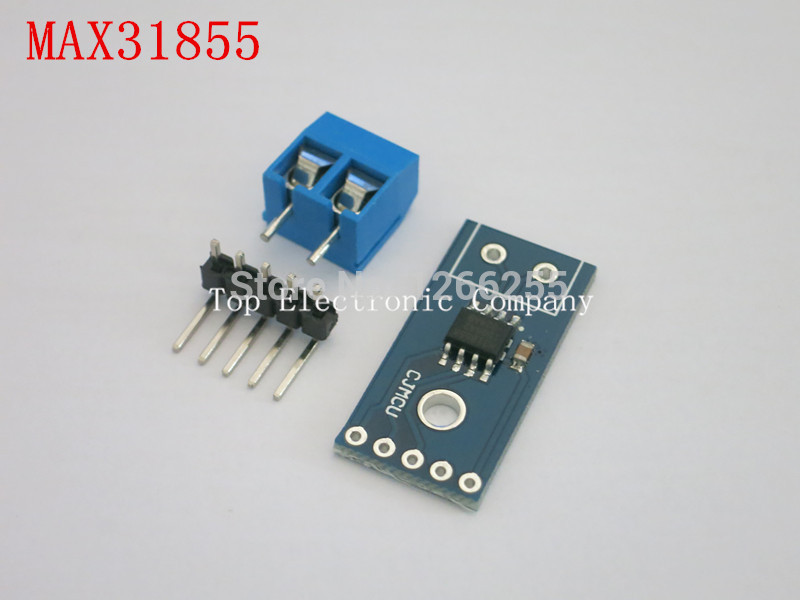
I also have an SPI thermocouple interface module which uses a dedicated chip (M31855) which interfaces via SPI.
So I may try connecting the erronous TC to the interface and read the temperature using a Maple mini. Im pretty sure there is an Arduino library for this chip.
BTW. Im also using a standalone digital thermometer which has a thermocouple probe, which I have positioned in the middle of there the PCB would lie, inside the oven.
But I need to double check the accuracy of this meter in melting ice water and boiling water
Well, at the moment its virtually useless.
One thermocouple is still reading at least 25 deg higher than the other one.
I swapped over the actual thermocouples and the left channel still reads at least 25 deg too high.
So I tried connecting both the left and the right thermocouples to a digital multimeter I have, that has a thermocouple input, and both thermocouples are fine.
So the problem seems to be the analog electronics that conditions the signal from the thermocouple.
I found a jpg image of a schematic that someone had drawn up. I’ve attached a bit of the schematic (sorry I can’t post it all but its too big and the quality is bad because it seems to be a jpg only)
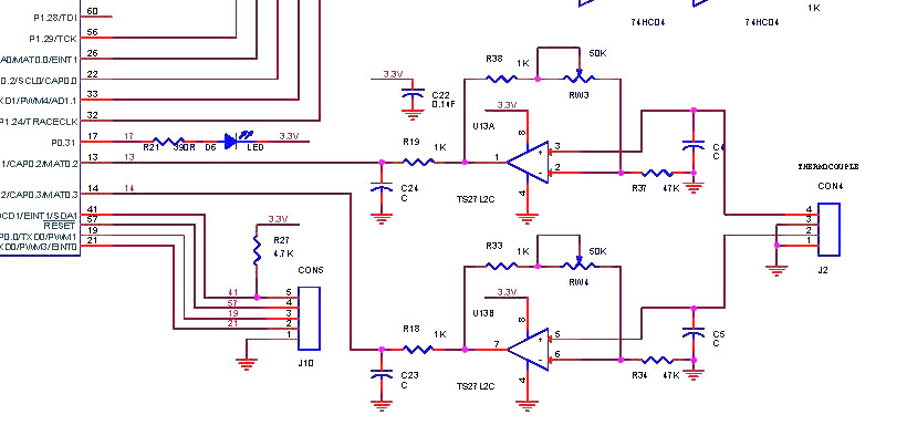
- t962_tc_inputs.jpg (82.33 KiB) Viewed 799 times
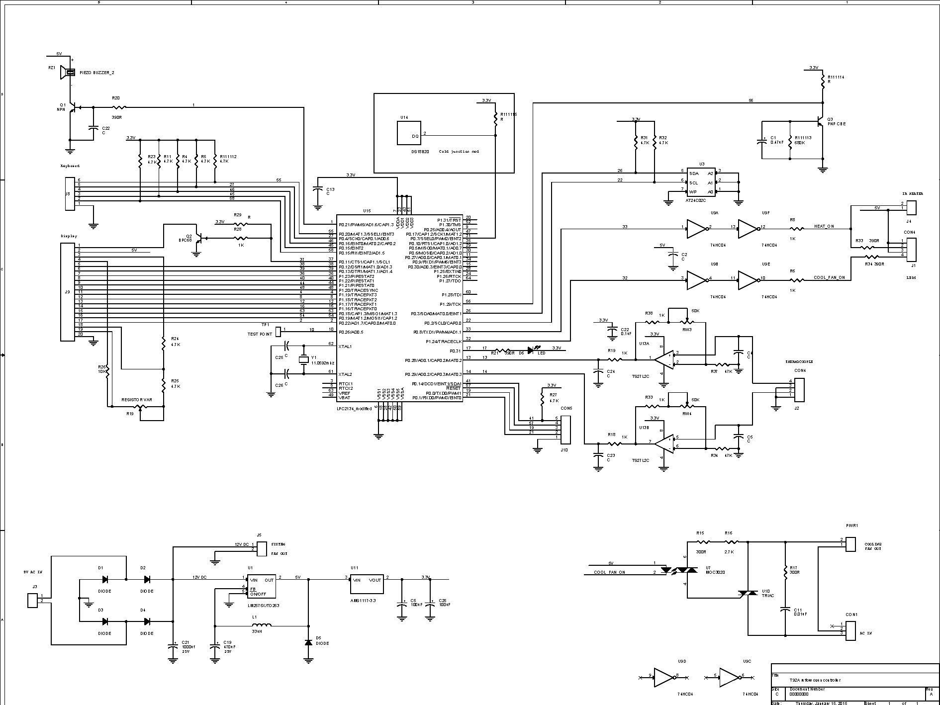
- T962.png (47.64 KiB) Viewed 796 times
I would assume that when working correctly, the opamp output should read somewhere between 0 and 3v3 depending on the gain (RW3 or RW4 presumably being used to control this) and the vale of the thermocouples.
If the opamp is bad, then you wont see any change when you fiddle with those pots. BTW do you not have a scope? This would perhaps be more sensitive than your DMM. The PigScope might even do the trick given the voltages we are dealing with here. Also double check the wiring to your thermocouples. The opamp may be one of these.
I did try adjusting the pot but It didn’t seem to make any difference to that channel.
I took the PCB out of the oven, and tried to measure whether it is broken or not, and it appeared to be OK, however its hard to tell as I was measuring its value while still on the board.
Someone else on Hackaday had a similar issue, and his opamp was faulty, so I wonder if I have the same problem.
These units are built as cheaply as possible, and I’d not be surprised if they were using reject parts etc.
I’m probably going to use an alternative fix which is already supported by the new firmware.
Its possible to use the Maxim Max31855 thermocouple to SPI chip, however the unit does not have any free SPI pins, so the firmware communicates with the 31855 via a I2C to SPI bridge IC ( as I2C is already used with some NV storage on the board)
I have some 31855 modules, but not the bridge IC, but I do have an Arduino Pro Mini 3.3v which I should be able to program to emulate the bridge IC, as the firmware only uses one command in the bridge.
However, I doubt I will have time to write the code for a few days
I ordered this one some months ago and I’m really happy with it while SMD soldering:
http://www.aliexpress.com/item/HK-MECHA … 59211.html
But I don’t own a reflow oven.
I did manage to get a small amount of solder paste locally (on Saturday), but I did need to drive about 20km to find somewhere that had the “lead” rather than the “lead free” version.
As most places seemed to have sold out of the “lead” version, I suspect its more popular than the “lead free” (as I’ve heard its more tolerant to the temperatures)
Re: Reflow oven
Currently I’m wondering if it was a mistake to buy it. But I was going to try to make a reflow oven using a toaster oven, and I suspect that would have been even more problems than buying one that almost works, and then modifying it to make it work properly (i.e with new firmware and better electronics).
At least the mechanics, e.g. the heaters and heat insulation on the T-962 are not too bad and it generally seems to be able to follow a heat profile, where as I think the modified toaster ovens have difficulty getting to 270 deg etc, unless you make loads of modifications and add extra heating elements etc (which would be hard to do and expensive – as you’d need to buy another oven to extract the heaters)
I’ve started to build the replacement electronics for the problematic Thermocouple inputs, but using some MAX31855 modules (from eBay) and an Arduino Pro Mini (3.3V)
The reason I’m using the Pro mini, is that I need I2C slave functionality and its not implemented in libmaple
Anyway. I connected up the Pro mini to the I2C pins (soldered to some resistors on the board), and after initially wiring SDA and SCL around the wrong way, because of an issue with someone elses post on how they wired their’s up.
I can get the Pro mini to listen to the traffic that the firmware sends out on address 0x28
Initially I was not able to send any data back to the reflow oven, because the I2C onRequest even was not being triggered. Fortunately I found a posting about a bug in the twowire lib, with a patch (comment out one line)
https://github.com/helenarobotics/Ardui … 2b39b0fbca
So I applied this fix and I now receive onRequest events, which I should be able to use to send data back to the oven.
But I will need to carry on with it this evening when I get some free time.
https://github.com/helenarobotics/Ardui … 2b39b0fbca
Thanks.
I found the explanation for why the AVR lib was not working, on the Arduino.cc forum
http://forum.arduino.cc/index.php?topic=125704.new#new
The ESP thing looks similar, but at the moment, www.esp8266.com is not responding, so I’ll take a look later to see if it seems to be the same bug
http://www.aliexpress.com/item/Brand-Ne … 11078.html
A handy alternative to SMD oven is a hot air SMD rework station, like this one that I have:
http://www.aliexpress.com/item/scotle-8 … 69194.html
I have the same hot air reflow station, but I have wanted to build a reflow oven for some time.
But then I thought it was cheaper to buy one.
However in the end, I’m not sure buying a cheap one, was such a good idea ![]()
where does the 270 come from, or is it because it’ll need the ramping up rate for the ‘take to 230c’ phase
from the ‘soak’?
stephen
I think the general issue with simple toaster oven reflow ovens, is that they dont have enough insulator or enough heating power to quickly ramp up after the soak phase, to melt the solder.
Im sure it is possible to convert a toaster oven to do this, but I was hoping that a cheap commercial oven would be a better option.
BTW.
As a bit of an update to my progress in using Max31855’s with the oven, I have successfully managed to get the open source firmware to think it has 2 external 31855 based TCs, by sending dummy data from the Arduino Pro Mini.
However when I send real data from a 31855, the temperature values shown by the oven are jibberish.
I suspect I have a byte ordering issue with the 32 bit data from the 31855 when transferred via I2C Wire.write(buffer, len)
The issue with the data, was indeed the byte order of the 4 byte buffer which was read over pseudo SPI via the adafruit lib
The byte ordering seems to have been reversed somehow, so I wrote some code to swap buffer bytes 0 and 3 and bytes 1 and 2, and now the firmware in the oven accepts the data and seems to read the correct temperatures.
I still however need to make a change to the firmware in the oven, because the bootloader in the Arduino Pro mini runs for about a second, so I need to delay the I2C search feature in the oven firmware by about a second, so that the pro mini is running when the I2C bus is scanned.
I also need to tidy up all my wiring with the pro mini etc
But at least I think that I’ve addressed the thermocouple issue and I also will have the option to add at least 2 more MAX31855 based thermocouples if I want.
I’m tempted to put a thermocouple on the tray right under where I would put the PCB, because the thermocouples in the oven are currently at the top of the chamber, and read higher than the readings I see with my stand alone thermocouple thermometer which is taped (with Kapton tape), just above the base of the drawer onto which the PCB would sit.
But I’ll need to order another thermocouple probe and also some more MAX31855 modules
58p uk free shipping
i’ve max6675 on boards, offer expired though
MAX31855 on a board £4.10 ukp
bare chip ~£7
top of the heap adafruit £16-£17
stephen
I did take a look for thermocouples last night and found a lot very similar to that one.
The only slight problem is that the pins on those connector don’t directly fit into the screw terminals on the MAX31855 module boards that I have.
Strangely, I can get the modules cheaper on eBay than I can from AliExpress
http://www.ebay.com.au/itm/NEW-MAX31855 … SwLVZVniqU
(there are £4 versions on ebay UK)
So I’ll order another 2 or 3 of those, so I have some spares
58p uk free shipping
i’ve max6675 on boards, offer expired though
MAX31855 on a board £4.10 ukp
bare chip ~£7
top of the heap adafruit £16-£17
stephen
I think the issue with my oven is some sort of electronics fault in the opamp.
I spent at least half a day trying to figure out why one channel was miss reading, and the other one was fine.
I resoldered various joints, and twiddled the adjustment pot, but to no avail.
So as I already have the Max31855 boards, it was just easier to do it that way.
I also can add additional thermocouples, and I’ve ordered another 3, so that I can have one thermocouple very close to the actual PCB, in the hope this will be be a better average reading of temperature in the oven.
I guess I could have gone done the analog route, and possibly managed to source another instrumentation amplifier, locally and built a complete new analog input section.
But I presumed that as the MAX31855’s are dedicated chips for this job, it would be better to use them.
Plus they also have the cold junction temperature as their output (which in this case I’m not sure I need really, because I though they were cold junction compensated, plus I already wired in a DS18B20 to act as the cold junction sensor for the existing analog inputs)
the wires are secured with a pinch plate and a screw
i’ve transplanted a few.
stephen
I have a similar thermocouple on my DMM, so I hoped I could just break the connector apart on the ones I’m getting from eBay
I’ll let you know how I get on..
I have a similar thermocouple on my DMM, so I hoped I could just break the connector apart on the ones I’m getting from eBay
I’ll let you know how I get on..
I will post again when the thermocouples arrive ( which wont be for several weeks)
Maybe you find some ideas here: https://github.com/0xPIT/reflowOvenController
BTW..
RogerClark wrote:cazimirb wrote:A handy alternative to SMD oven is a hot air SMD rework station, like this one that I have:
http://www.aliexpress.com/item/scotle-8 … 69194.html
I finally got the oven going using MAX31855’s and an Arduino pro mini as an I2C to SPI bridge.
It took me a while to figure out how what I needed to send to the oven over I2C, but by looking at the code for the oven firmware, I noticed that if it receives 0x00000000 when it requests a TC value (during start up), it reads this a no TC attached to that port
So I have some very simple code, that listens for incoming I2C events, where the first byte is the command, and then in the onRequest handler, it either sends back 0x00000000 or it reads the Max31855 via SPI and returns the real value.
But for some reason I had to byte swap all 4 bytes of the data as it seems to be in the correct order (I’m using the Adafruit lib to read in the data from the Max31855’s but I may go back to plain old SPI)
The only other change I had to make was to the oven firmware, because the Arduino bootloader, in the pro mini, needs to complete and the sketch needs to be running when the oven scans for I2C devices. So I had to put a 2 sec delay in the oven’s init routines (and sort out the WDT which was kicking in because of the delay)
But its all done now ![]()
I’ll post a full writeup on my blog when I get time.
I’ll also post all of my code, once I’ve modified the Pro mini code to just use SPI.
The only other change I had to make was to the oven firmware, because the Arduino bootloader, in the pro mini, needs to complete and the sketch needs to be running when the oven scans for I2C devices. So I had to put a 2 sec delay in the oven’s init routines (and sort out the WDT which was kicking in because of the delay)
The issue is that I need I2C slave functionality, and Im not sure its been written for the Wire lib for STM32 etc.
Its definitely not supported in the version in my repo, (i checked).
So I had to go back to using an AVR board for this.
I know I could have written the I2C slave code, but I just want to get the reflow oven to work.
I could also just flash the AVR board without a bootloader, as I have the hardware to do it.
But I was trying to create a fix that I could publish, for other people to use, who don’t have access to lots of fancy hardware.
So the easiest thing to do was to modify the oven firmware, as its really easy to compile on Linux.
BTW. Even the GD32 would not help, as the oven firmware scans the I2C bus within a few milliseconds of startup, so my solution would not work for any board with a bootloader unless I modified the oven firmware, to delay its scanning.
Edit.
Actually. I just found that there was a version of the I2C code written for libmaple that included I2C slave functionality
http://forums.leaflabs.com/topic.php?id=1543
I will see if its possible simply to update our HardWire lib with this functionality
I eventually coded a I2C slave to interface with the Maxim thermocouple chips (which are SPI) using an Arduino Pro mini.
I put the oven back together using the Maxim chips for both internal thermocouples and the problem seemed to be fixed as both thermocouples read the same value at room temperature
Anyway, When I tried to use the oven, I found it was not getting hot enough to melt the solder paste, unless I set the temperature at about 30 deg higher than is correct.
Initially I thought the issue was that the oven has hotspots as its not got anything inside it to circulate the air I.e no internal fan.
So, in case this was the issue, I thought I’d get out one of those hot air paint stripping tools, and blow air in through the front by opening the drawer a bit, and blowing it in.
Anyway, Looking at the thermocouple readouts on the display; even if I blow air in, the thermocouple on the right seems to read higher than the one on the left,by around 20 deg, perhaps more. This was even if I move the hot air tool around from one side to the other.
So, I’m now not sure if one of both of the thermocouples is faulty, which may or may not have been the original problem.
It did also give me an idea for a better reflow oven…. Use a hot air paint stripper !
As far as I can tell, they are capable of delivering hot air well in excess of the 225 deg C that is required for lead based solder and actually capable of delivering air in excess of 300 deg (some places even quote 400 deg C or more, much more..)
I can get a “variable” heat one for $50 locally, but in reality, you would need to strip the thing apart, and control the motor and the heating elements separately, as the motor speed will be too high, as its likely to blow the components off the board.
Perhaps in conjunction with a toaster oven as a enclosure, this could be a better solution to reflowing boards .
Is there any way to swap the thermocouples round and see if the problem follows the thermocouple, or stays at the same place, or are they bonded in place? If you can, then if the hotspot remains in the same physical location, then the thermocouples are fine, and the physical layout is suspect. If the hotspot remains on the same thermocouple, then the thermocouple is suspect.
I must admit Im getting a bit lost about whats going on.
I looked inside the oven, and all it has is 2 of those cheap thermocouples from eBay with the woven white covering on the wire.
They stick down into the middle of the oven, about half way between the 2 IR heater rod things.
Initially, I thought it was a heat spot issue, but blowing hot air inside (no heaters on), still have me the same sort of error.
I can swap over the connections, as I suppose there could be a fault on one of the Maxim chip interface boards, which would not be impossible, but its strange that swapping from analog input circuits on the main PCB to extrnal interfaces on the two thermocouple digital interface modules / boards which use the dedicated Maxim chip to do the conversion, still seems to end up with the same sort of problem as I had on the analog electronics
I have 3 more thermocouples on order from China (via eBay), so I think I will wait until they arrive, so I can do some comparisons
Do we have any spec for these cheap thermocouples?
if different output, its the thermocouple else if pretty close try with the other circuit if still pretty close wait for
thermocouples and repeat, if still consistent try a third circuit else scratch head?
out of ballpark thought, try squeezing bead between insulation and a higher temperature, ‘dry’ joint?
stephen
Or, as some documents suggest, a ≥ 1 MΩ resistor.
Floating TC’s can behave very erratically.
Or, as some documents suggest, a ≥ 1 MΩ resistor.
Floating TC’s can behave very erratically.
is the MAX31855 similar? seems not from the pdf
seems mainly 5v/3v3 problems(?)
MAX31855 k type site:http://forum.arduino.cc ![]() need a tongue in cheek smiley :-J
need a tongue in cheek smiley :-J
stephen
Thanks for all your responses.
The interface modules I am using are the ones with MAX31855 chips on them.
When i finally took a look right inside the oven, the thermocouples looked like this type
http://www.ebay.com.au/itm/1PCS-K-Type- … 1216872256
except without the insulation at the end of the cable.
But I noticed that the white coloured woven sheath around the cable has turned light brown with heat damage.
It looks like that woven heat coating is not designed for the temperatures that the thermocouples are exposed to.
Actually, i have a Digital Multimeter which has a similar thermocouple input, and i had taped it to the metal tray of the drawer where you put the PCBs and after my test runs while debugging the thermocouple stuff, I found the woven outer on my probes cable was also rather burnt.
I think they have used the wrong sort of probe for this, in order to save money.
Initially when I was going to use a toaster oven as reflow oven, I bought a thermocouple temperature probe, like this one
http://www.ebay.com.au/itm/Temperature- … 1556418430
but unfortunately it has now stopped working, but I will take it apart to see if its a cable fault.
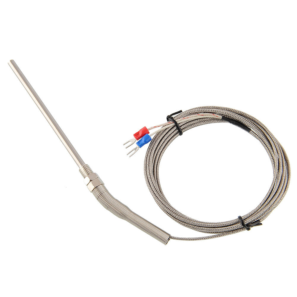
I see that there are probes like this
http://www.ebay.com.au/itm/K-Type-5cm-P … 1243583738
which I think look like they are more appropriate for the job.
I didnt really intend for this to be a development project. It was supposed to be an easier way to reflow boards, than using my hot air reflow gun. But its ended up taking several weekends already.
But its hard to know at the moment, whether a IR heating based oven is ever gong to give good results, or whether I should have gone done a home made route, and buy another 2000W hot air paint stripper gun, and use it to heat a toaster oven.
I really think this could actually end up being a very good convection reflow oven.
And it would probably have been quicker to build than the time Ive spent trying to get this commerically made oven to work.
It has been a few years since I have worked with thermocouples, but I designed the dual-EGT monitor for a Rotax engine in a friend’s Europa experimental aircraft. Sensors made for EGT are serious, such as:
http://www.ebay.com/itm/EGT-Thermocoupl … 0938569825
And have a nice metalic braid/cover.
You can often find these at custom automotive parts shops.
Ray
I did notice some others like that, but the internal arrangement in the oven seems to be that the thermocouple end gets dangled into the middle of the oven, ie hangs down about 5cm, and if I used anything but probe or the type they used, then the end of the thermocouple would be a lot closer to the top of the oven, and the temperatures probably read a lot higher than where the PCB is at the bottom.
I think my best bet would be to go for the long probe type and stick it in as far as I can manage, without fouling the PCB.
i.e Its unlikely I’m going to be soldering a PCB that has components higher than about 1/2 inch or 1 inch at the most, so it probably makes sense to get the probes as low as possible.
It looks like its worth me getting a 2 of these to test, as they look similar to the ones you linked to
http://www.ebay.com/itm/1pcs-3M-Stainle … SwPcVVzGWv
It looks like its worth me getting a 2 of these to test, as they look similar to the ones you linked to
I’ll take a look, but I”m not sure if any of the eBay vendors have that information.
I’ve already ordered a variety of thermocouples last weekend; mainly some of the simple ones with what looks like blob of solder (I know its not solder) on the end. They were relatively cheap, so I thought it was worth a gamble.
But its going to take a few weeks before they arrive.
<…>
I’ve already ordered a variety of thermocouples last weekend; mainly some of the simple ones with what looks like blob of solder (I know its not solder) on the end. They were relatively cheap, so I thought it was worth a gamble.
<….>
I eventually coded a I2C slave to interface with the Maxim thermocouple chips (which are SPI) using an Arduino Pro mini.
I eventually coded a I2C slave to interface with the Maxim thermocouple chips (which are SPI) using an Arduino Pro mini.
I ended up just using an Arduino Pro mini as it was easier.
I don’t have time at the moment to merge the old I2C Slave code with the existing code, but you could take a look to see how similar the version with the slave functionality is, to the current code
thought 5 or 6mm wire mesh, 19-25mm up from board, and use the wire ones for any points of interest?
ok first thoughts were peg board, metal, inertia, heavy duty, wire coat hangers, weaving, weave probe wire to ‘fix’ position
srp
It has been a few years since I have worked with thermocouples, but I designed the dual-EGT monitor for a Rotax engine in a friend’s Europa experimental aircraft. Sensors made for EGT are serious, such as:
http://www.ebay.com/itm/EGT-Thermocoupl … 0938569825
And have a nice metalic braid/cover.
You can often find these at custom automotive parts shops.
Ray
Perhaps I may get time over the Christmas holidays
I ended up just using an Arduino Pro mini as it was easier.
I don’t have time at the moment to merge the old I2C Slave code with the existing code, but you could take a look to see how similar the version with the slave functionality is, to the current code
I ended up just using an Arduino Pro mini as it was easier.
I don’t have time at the moment to merge the old I2C Slave code with the existing code, but you could take a look to see how similar the version with the slave functionality is, to the current code
So.. I didnt use the STM32 for this.
So.. I didnt use the STM32 for this.


