viewtopic.php?f=3&t=731
– Ray
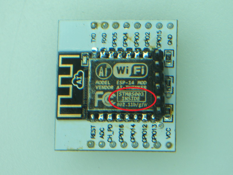
For anyone interested… looks like a 12E to me but I have NOT compared fully:
http://www.aliexpress.com/item/The-stro … 95326.html
From an email promotion directed to my alter-ego, the author ![]()
The 12E is $1.90:
http://www.aliexpress.com/item/New-vers … 17567.html
Note: I have not utilized the 1st vendor, but I have placed and received several orders from Great Wall all with exceptional service – your results may vary. Additionally, I place 10x orders on most occasions which generally results in a Box” instead of a “bag.”
Ray
That why the pinout down are GPIOs from STM8, not the one from the ESP.
Personally, I won’t purchase those one, since if I want to add an MCU, it won’t be a 8 bits.
I prefer sticking on ESP-12E.
That why the pinout down are GPIOs from STM8, not the one from the ESP.
Personally, I won’t purchase those one, since if I want to add an MCU, it won’t be a 8 bits.
I prefer sticking on ESP-12E.
(btw, here is a thread were the datasheet of the STM8 is provided : http://www.esp8266.com/viewtopic.php?f= … t=5#p27137)
Some people say that since ESP8266 is busy doing the Wifi, some time critical applications need the handle I/O with some other MCU.
Why not then put an F103 for this kind of thing instead of that small STM8 which has only 8 K Flash and 1K RAM ?
But this ESP-14 is really an unknown product to the community, we don’t even know how both CPU are linked together, especially on software side.
Is the “upload” is done on ESP8266 or STM8 ? Can both firmwares are upgradable ?
If ESP8266 rely on AT command, it is well known in the community that this firmware is very limited, for example, you can’t have both TCP Server and TCP Client at the same time. Parsing and issuing AT commands make a lot of burden into the second MCU, That is also the main reason that we see a lot of post on the forum where people have parsing issues such “busy”, etc.
I feel that ESP8266 should stay the main MCU, and Arduino framework or plain SDK, and if there is an STM8 around, it should be a slave I2C and dedicated to what it is there for “time-critical I/O”.
… but too many unknown for now …
I have two of them but I was not able to communicate with them with my cheap ST-Link clone.
But I agree that I will have used another chip instead of STM8.
But this ESP-14 is really an unknown product to the community, we don’t even know how both CPU are linked together, especially on software side.
<…>
… but too many unknown for now …
http://www.electrodragon.com/product/es … rettyPhoto
I’d just as soon hook up a STM32, micro, or something vs trying to mess with the STM8. I guess I missed the point of the STM8 onboard since a lot of people just program the 8266 to do what they want or just connect it to something else.
I’ve got too many to-dos right now anyway. lol
<…>
I guess I missed the point of the STM8 onboard since a lot of people just program the 8266 to do what they want or just connect it to something else.
http://www.cnx-software.com/2015/10/26/ … stm8s-mcu/
Between that and the datasheet for the micro it does appear that it gives more gpio options plus exta ADC inputs. It’s tough figuring out which ones are routed out and what types are available for use. Then comparing what ESP8266 I/O was compared to the STM8.
Seems like we have a micro, running a micro that talks to a wifi. lol
Boy, talk about a lot lost in translation. Reading the descriptions it’s clearly a lot was translated from Chinese on the Ali site. I haven’t got around to playing around with my 8266 modules yet. I just got a ESP8266 ESP-12 NodeMCU Lua module.
Guess we will have to see when more accurate details come out. Plus since some are out already there will be Hackaday posts that might shed some light.
<…>
Guess we will have to see when more accurate details come out. Plus since some are out already there will be Hackaday posts that might shed some light.
http://www.st.com/web/en/resource/techn … 024550.pdf page 65/103
On the other hand, the STM8S103F3P6 has 100k erase/write program memory cycles
http://www.st.com/web/en/resource/techn … 226640.pdf page 69/118
would we need to write a new core for stm8?
optimist that i am
the main visual difference for a 12 v 12E, is that the 12E connections now extend to a third side.
there’re some 12E’s around on a pcb and breakout pins with a 3xAA battery box at a pretty good price. immediately deployable.
now you’ve got me wondering if they are in fact 12Es….
heaves on battery box to reveal – they’re not. oh well they were way under a £1 ukp.
stephen
http://www.st.com/web/en/resource/techn … 024550.pdf page 65/103
!On the other hand, the STM8S103F3P6 has 100k erase/write program memory cycles
would we need to write a new core for stm8?
optimist that i am
<…>
oh well they were way under a £1 ukp.
stephen
STM dev tools being?
stephen
STM dev tools being?
stephen
I’ve started to look at the STM8 because its used in some cheap volt meters, (you can buy on eBay etc), but this will have carry-over into the ESP8266-14)
e.g
http://www.ebay.com/itm/4-Digit-4-5-30V … XQoiJRhhnM
What I find amusing, is that they even list it uses an STM8s003, so I guess they expect people to want to use the STM8 for other uses
I have a feeling a lot of other similar devices also use the STM8 e.g This one looks suspicously like it also uses an STM8 (but its hard to know for sure)
http://www.ebay.com/itm/Red-LED-5-Digit … xyQyJRlcPq
So far, the only compiler I installed for the STM8 is the IAR, however there is a free version if the code size is less than 32k (and I think the STM8 has limited code size anyway, so this may not be an issue) . But you do need to register with IAR and get a license key etc and its a Windows only compiler..
This compiler is also a possibility http://www.cosmic-software.com/download.php but again it appears to be windows only and code size limited
There is also this on http://fun4diy.com/stm8cc.htm (but goodness knows what its origins are, and the pdf that comes with it, is in chinese)
There is another list of tools here
http://www.emcu.it/STM8.html#STM8S_Some … _tools_are:
Personally, I’d rather not use IAR, even though I have it installed, and may try the SDCC even though their last news update was over 6 months ago
Anyway. I now have 2 STM8 volt meter modules, and of course a ST-Link programmer, so when I get chance I’ll at least connect the ST-Link to the STM8 and see what happens !
<…>
Anyway. I now have 2 STM8 volt meter modules, and of course a ST-Link programmer, so when I get chance I’ll at least connect the ST-Link to the STM8 and see what happens !
I’ve actually had to heat up one of these volt meters with a hot air reflow tool (set to 100 deg C) to try to remove all the hot glue that they use to keep it in its bezel / case. (so I can get to the connections on the board)
and… Its still working.
But of course there is still the chance I will fry it some other way ![]()
BTW. Re: Arduino core for STM8
It would need to be written from scratch, as we can’t leverage anything from libmaple as its an entirely different processor (older)
There is a Standard Peripheral Library for the device
But the license appears to be similar to the old license on the STM32 SPL.
This has not however stopped other people posting files from the SPL in their github repos, or the entire SPL on google code
Also the license is ambigous about what the “Product” is. As it says its “You or Your’s end user’s product or system”
If the product was an Arduino core, i.e a software “system”, it would be copy-able
But I guess it all depends on if anyone has time to attemp to write a core using this SPL.
http://www.st.com/web/en/resource/techn … 024550.pdf page 65/103
!On the other hand, the STM8S103F3P6 has 100k erase/write program memory cycles
BTW
I tried to connect one of my STLink boards to the board I have with an STM8 on it, but I can’t get it to connect. It may be a Magic Smoke club problem, as initially I had a short from SWIM to the 3.3V supply , so I guess I could have fried that STLink adaptor.
But it didnt work even after I removed the short (solder bridge)
I will need to find my other STLink board, but I have misplaced it at the moment.
Anyway, I got around to mounting the board on a breakout and affixing the 6-pin header. The ESP 14 was mounted using hot-air and the header was mounted using a small 35W (but I use a diode inline, so I’m guessing around 18W – 20W is the final heat.) The results look good even under a microscope.
Now, to get on to figuring out what I need this for…
Ray
Note that the -14 is mounted on a -12 breakout: The legends do not match!!!
- DSCF1976_web.jpg (130.21 KiB) Viewed 1386 times
How do you program the ESP8266? It looks like all the signals on the pins are STM8 signals
How do you program the ESP8266? It looks like all the signals on the pins are STM8 signals
Apart from peeling of the metal housing, I wonder if the Program input ( I cant remember which gpio on the ESP it is) is connected to the STM8.
Perhaps the STM8 would be fast enough to act as a serial bridge to the ESP8266
Once you got the OTA sketch into the ESP you could use OTA after that to reprogram it.
In fact, I’m be tempted to remove the metal if you cant get to the ESP any other way
OK. I hadn’t noticed that GPIO 0 on the ESP was broken out to that pin.
However the STM8S003 only had one UART, which I presume is wired to the UART on the ESP
So the upload sketch would either have to use software serial (which I find generally unreliable at high speeds), or some other method
I suspect some sort of bit banged SPI style interface would be required on the input to the STM8. Looking at the SPI it specifically mentions “SPI master mode”, but does not mention Slave mode, so I suspect its not supported.
I guess you could run it as the master and run something else as the slave. (Actually this may be the best bet).
I would suggest using the Maple mini as a SPI slave (even if its just bit banging the data out to the STM8, as I expect that a tight loop reading the SPI Clock directly polling the hardware, would be fast enough to respond to the clock)
However the flash size on the Maple mini is too small, as the Basic OTA sketch is over 200k.
Perhaps use an ESP8266 to act as a SPI slave, but you’d need to use the same method and directly poll the hardware GPIO
BTW. I don’t think interrups could be used for the SPI slave, as I’ve found there is significant overhead, on calling the ISR, which slows things down a lot.
Fortunately, I only have 3 of these small paperweights. I was thinking that if Rx/Tx of the STM8 were broken out, I could just use Rx as Tx and Tx as Rx and power only the ESP8266 section.
But right now, my head hurts (from the barometric pressure here in Georgia. We got the tail end of the winter storm with maybe 1/32 inch of frozen precipitation; nothin’ like the feet of stuff up on the eastern seaboard.)
Ray
Are you sure it doesnt have 100k
I just looked at http://www.st.com/web/en/resource/techn … 024550.pdf
And it seems to say the STM8S003F3 has “100 k write/erase cycles”
rlp�n��lbn�|l�l��b��nn�l`rl��n���nn����rnnn�l�b�bp�lbll`rl�n’t use rtc mem data
rl��rl��
Ai-Thinker Technology Co.,Ltd.
ready
AT+RST <—- I typed this ONLY
OK
ets Jan 8 2013,rst cause:2, boot mode:(3,6)
load 0x40100000, len 1396, room 16
tail 4
chksum 0x89
load 0x3ffe8000, len 776, room 4
tail 4
chksum 0xe8
load 0x3ffe8308, len 540, room 4
tail 8
chksum 0xc0
csum 0xc0
2nd boot version : 1.4(b1)
SPI Speed : 40MHz
SPI Mode : DIO
SPI Flash Size & Map: 8Mbit(512KB+512KB)
jump to run user1 @ 1000
�n’t use rtc mem data
rl��rl��
Ai-Thinker Technology Co.,Ltd.
ready
Warning …. if you use an old-style breakout board DO NOT even look at the legends on the board … you will immediately short out your power supply. Also, do not connect the 5V from the serial to anything, only connect the Gnd from the CP21xx or FTDI (just 3 wires only.) Pins 4 SWIM & pin 8 are Grounded in my test and pin 16 M_VDD and pin 17 E_VDD are connected to 3.3V.
Obviously this leads a lots to ponder…
Ray
Thanks for the correction ![]()
100 rewrite cycles (arrrggghhh), that’s madness. I suspect that in the course of a development you’d need multiple devices, as any reasonable scale project probably has more than 100 uploads
@Ray
I was wondering if the storm had got as far south as Altanta…
I don’t think I’ll be rushing out to buy a ESP-14, but its interesting to see that they broke out the TX and RX from the ESP (as well as having it connected to the UART I presume on the STM8)
Let me know if you managed to get an STLink talking to the STM8, as I’ve had no luck with that myself.
I have some STM8 based volt meters, and I worked out which pins on the edge of the board with SWIM and NRST and hooked them up to one of my STLink dongles, and ran the STLInk program I normally use for the STM32, but it didnt recognize the device.
I tried various settings including the JTAG setting and lower speeds and various connect under reset stuff etc, but still no joy.
I did initially have a short between the SWIM pin and Vcc (tiny solder bridge between 2 pins) that I’d not noticed. So I don’t know if I’ve damaged that part of the STLink dongle (i.e its not the same pins as used for the STM32)
In fact I’m not entirely sure if I should be using the same STLink program, as the program is called “STM32 ST-LINK Utility” – but I couldnt seem to find a STLink program for STM8, as I kept getting redirected back to the STM32 STlink download page.
The only info I have found for uploading to the STM8 was within other people’s IDE’s where it looked like they may be directly communicating with the dongle.
But I suppose I should do 2 things
1. Connect my scope to the NRST and SWIM pins and see if they are toggling
2. See if I can find a special STM8 stlink program
Edit.
I tried by STLink again but I don’t think the STM32 ST-LINK Utility is capable of connecting to the STM8 (though I could be wrong)
I’ve searched the manual for the utility and it only mentions STM8 once and thats in relation to the hardware.
There is no mention of the SWIM connection.
I suspect that the STM Visual Programmer software is what may be required to connect to the STM8, so I’m downloading it now, but ST’s site is very slow
I’ll post again if I make any progress
PS. I did wonder whether it would be possible to make an Arduino core for the STM8, but as it only has 1k of Ram, things like the serial buffer would have to be reduced and even then I’m not sure much room would be left for a useful sketch
<…>
PS. I did wonder whether it would be possible to make an Arduino core for the STM8, but as it only has 1k of Ram, things like the serial buffer would have to be reduced and even then I’m not sure much room would be left for a useful sketch
OK.
I think my first computer (Sinclair ZX80) had 1k in it, and I remember struggling to get an upgrade of another 3K to push it to the stratospheric levels of 4k !!
Of course the program had to sit in ram on those things, so it was not just a problem of variable space
Still its nice to have the 20k in the STM32 of the even larger memory in the ESP8266
I managed to connect to the STM8
But I needed to download the STM Visual Programming tools
http://www.st.com/web/catalog/tools/FM1 … partnumber
Well, its telling me that its read protected at the moment, but I don’t want to flash it yet, as I’d waste 1% of the available rewrite cycles !!!
But at least its connected.
BTW. I guess just doing the Erase chip to clear the read protection will waste 1% of the rewrite cycles ![]()
BTW. I guess just doing the Erase chip to clear the read protection will waste 1% of the rewrite cycles ![]()
100 R/W cycles… does seem small, but seeing that I am having a darn difficult time trying to make up a use for the module, well, it may never get cycled even only once!
Ray
I see what you mean about its usefulness.
It doesn’t resolve the issue of the lack of pins.
I have found with the ESP-12 that there is a distinct lack of usable pins, as some pins must be pulled low, and some must be pulled high
The 12E is better but would benefit from being a bit longer and having a few more pins (Though I’m not sure how many GPIOs that the ESP8266 has)
I presumed the reason for using the STM8 married to the ESP8266 was to have more pins, and to allow offloading of some tasks, but as previously discussed, they should have used the STM32 not the STM8 (stupid decision in my opinion), and also broken out more pins.
And using the GD32 would be even better as the processing power on the GD32 is considerably faster than the STM32, because of the higher clock speeds and zero wait time on the Flash.
So… You really could offload processor intensive tasks to the GD32 as it would be faster than the 80Mhz core in the ESP8266.
And of course with either the STM32 or GD32 you could have a USB interface to the ESP8266, which everyone would lap up.!
<…>
I presumed the reason for using the STM8 married to the ESP8266 was to have more pins, and to allow offloading of some tasks, but as previously discussed, they should have used the STM32 not the STM8 (stupid decision in my opinion), and also broken out more pins.
The ESP-14 is reported to have the STM8S003F3P6 chip; I have not popped the can to verify and have not connected the lost STM_LInk. If truly a STM8S003F3P6, the chip does support native USB.
Having native USB for the ESP8266 would be most interesting and a few extra I/O ports to boot. If we can separately access and program both uC independently … maybe things could become interesting?
Added… almost beginning to look like a Wio_Link but I cannot (yet) find a schematic for the USB implementation of that ESP8266 based board.
Ray
This USB would be driven by some software like V-USB, because the chip itself hasn’t any USB hardware.
http://www.st.com/web/en/resource/techn … 024550.pdf
This USB would be driven by some software like V-USB, because the chip itself hasn’t any USB hardware.
http://www.st.com/web/en/resource/techn … 024550.pdf
I tried to compile and upload an example to my STM8, but had to give up due to lack of time.
I am using the free “KickStarter” edition of the IAR IDE/compiler, but it did not seem to directly communicate with the STLink and It didn’t seem to generate a bin file that I could upload using STM’s Visual Programming Toolset.
I’ve never used IAR before, and was quite surprised about how dated the user interface looks, i.e It looks like a Windows 95 program, with old style expanding menus etc.
But I guess it does the job, and people who buy the commercial version, do so for the functionality ( or because there is no alternative)
IAR seemed to just run the program in some sort of simulator, (which would probably be handy if the STM8 only has 100 write cycles).
There are some other free commercial alternatives, to IAR, which I may try. But at the moment I think I will park this.
As its probably more hassle than its worth for me, in terms of repurposing a 4 digit LED volt meter to convert it into a digital temperature meter or a digital flow meter etc.
I would probably be better off looking for an Ili9341 display in a nice bezel, and wiring a Maple mini etc to the back of it.
PS. on the ESP8266 I’m battling a strange issue, where if I pull GPIO16 low for more than a split second the ESP12E seems to crash
<…>
PS. on the ESP8266 I’m battling a strange issue, where if I pull GPIO16 low for more than a split second the ESP12E seems to crash
But it should not prevent from using it as input as well, the only thing is that it doesn’t have weak pullup like other GPIOs, it has a weak pulldown instead.
This USB would be driven by some software like V-USB, because the chip itself hasn’t any USB hardware.
http://www.st.com/web/en/resource/techn … 024550.pdf
It seems that the second is derived from the first according to README, but with the russian comments translated.
But it should not prevent from using it as input as well, the only thing is that it doesn’t have weak pullup like other GPIOs, it has a weak pulldown instead.
I was reading here and ran across this statement;
A quick note about using GPIO0 as SCL instead if GPIO14
In the case where you want to use both I2C and SPI in your application you need to move SCL to pin 0 instead of pin 14. This is because the SPI interface shares the clock signal (SCK) with the I2C interface.
All +One modules are prepared for this and can easily be reconfigured using on board solder jumpers.
Interesting. I cannot remember reading the common clock statement previously.
Ray
Thanks for that.
I’m still battling the GPIO16 crash issue. It looks like if I pull it low via 1k it works fine.
But I need to confirm if this is just an ESP-12E issue due to some internal wiring inside the metalwork of the 12E or something else
About GPIO0… ummm, Using the pins that controls the programming has always been an issue for me.
i.e the problem I find with the regular ESP-12 is that there are not a lot of free pins. Because some are dual purpose. And using the dual purpose pins, e.g. GPIO16 and also GPIO0 and GPIO15 can come back to bite you..
Like its done for me with GPIO16
i.e when I’m using the STM32, I’d not really want to use Boot0 or Boot1 as GPIO in case the peripherals effected the reboot
<…>
About GPIO0… ummm, Using the pins that controls the programming has always been an issue for me.
i.e the problem I find with the regular ESP-12 is that there are not a lot of free pins. Because some are dual purpose. And using the dual purpose pins, e.g. GPIO16 and also GPIO0 and GPIO15 can come back to bite you..
Like its done for me with GPIO16
i.e when I’m using the STM32, I’d not really want to use Boot0 or Boot1 as GPIO in case the peripherals effected the reboot
I tried another board on which I also use a ESP8266 and GPIO 16 didn’t seem to crash.
The boards are identical in how they use GPIO16 for a button input. So Im putting this one down to a faulty ESP-12E.
I find the ESP SDK to be a bit unstable.
I suppose I need to update to the latest version, from github, but i think it only works with the latest IDE. So I think I will need to run the latest IDE on one machine just to use the latest ESP stuff.
e.g I have been trying OTA from a http server, but in the version of the sdk Im using, It doesnt tell you went its complete, it just reboots.
It also seems to fail to update around 75% of the time.
I have not tried using a local http server e.g running on my PC, to establish why it fails so often, and the update files are effectively on the same server as this forum.
Re:latency of functions
I had a look at how things like DNS resolving are done, internally in the ESP8266 Arduino core, and I can see the trick they are using, so that they turn what was Non-Blocking functions into blocking functions, so that it makes coding easier.
However, personally in a lot of cases, I’d be happy to use event driven programming. I use event driven programming all the time for Javascript and other languages, because Im normally writing code which have complex GUI’s , so it would be second nature to me.
However from what I read, when someone suggest that the ESP Arduino core, make event driven functions available to the sketch, that it seemed to be thought of, as contrary to the “Arduino” way of doing things.
However from what I read, when someone suggest that the ESP Arduino core, make event driven functions available to the sketch, that it seemed to be thought of, as contrary to the “Arduino” way of doing things.
I think I will just bypass some of the Arduino ESP stuff and call the underlying API when its more suitable to do so.
The main benefit of using Arduino, is that the setup etc is easier.
I started programming the ESP over a year ago, long before the Arduino core was written, when the only option was a special Linux VM (which I ran under Windows).
But that was a pain to use.
The other benefit of using Arduino or dev systems like MBED, is the community user base and english language support.
Which is generally lacking for the Chinese designed products.
I have some Spark modules, but never got into them, and the cost is too high to make them practical for my projects.
The EMW3165 is also a great product, but suffers because of lack of community support.
I may end up going back to the EMW3165 at some point, but at the moment Im too far down the ESP8266 road to chuck them out of existing projects
I suppose I need to update to the latest version, from github, but i think it only works with the latest IDE. So I think I will need to run the latest IDE on one machine just to use the latest ESP stuff.
Thanks.
Actually, I just installed via the Boards Manager on a different machine, that has 1.6.5 on it, and it installed OK.
I suppose the stable version is the one to use.
On my other machine, I’d actually moved the installed package files from Arduino15 as I don’t like the vagueries of relying on the same version downloading onto another machine, i.e moved the ESP8266 core into the hardware folder, and backed it up as part of my project, so that if I come back to it next year etc I’d be able to re-build the project.
But I think when I tried to do the same with the latest version 2.0.0 I had some issues moving it, and mistook the problem for an incompatibility with 1.6.5.
I noticed that on the Arduino ESP8266 GitHub repo readme.md. it states the Arduino version as 1.6.5, so perhaps they decided to stay with 1.6.5 as well??
I know they were trying to have simultaneous support for 1.6.5 and 1.6.6 etc but it was causing caching problems etc. But I’ve not been monitoring this closely as I’ve been too busy on other stuff.
But I will try my code on the latest stable version, to see if my issue with GPIO16 happens to be a SDK think that may have been addressed in V2.0.0
Re: ESP8266-14 + STM8
I have some ESP-03 modules. So I’m going to glue one of them onto the underside of either a GD32 or a Maple mini, or a Red Pill.
The GD32 and Red Pill boards are best suited to this, because if you remove the STLINK pins, the end of the board is fairly free without too much to hinder placing the ESP-03 on the underside of the board.
I think this would be a better solution than the ESP-14
I suppose the stable version is the one to use.
<…>
I have some ESP-03 modules. So I’m going to glue one of them onto the underside of either a GD32 or a Maple mini, or a Red Pill.
<…>
I have some quite strong double sided tape. I’m not sure what its intended use is.. I suspect it may be for carpets, but its really strong !
I also some double sided foam tape for uneven surfaces
Actually… I have a large collection of tapes ![]()
…
Actually… I have a large collection of tapes
<…>
Tape falls in to the “you can never have too many” category (like multimeters, screwdrivers, clamps, spanners, nuts, bolts, washers, screws, nails, random electronic components, glues… to name but a few).
https://gregwareblog.wordpress.com/2016 … ts-stage1/
https://gregwareblog.wordpress.com/2016 … ts-stage1/
…. update:
Nothing there I did not know although it is a great summary. What I would really love to see is a completd schematic of the -14 to determine all interconnects to the 8266. Because…
Now, while writing this, I realized that using the STM8 as a I/O slave, I would have to find ‘drivers’ coded for the STM8 for the various peripherals we commonly use, e.g DS18B20, WS2812, DHT11, HX711, …
Too bad STM8 has not been “Arduinoized” as much of the library issues would be solved or easily solvable … well, maybe not with such sparse resources of flash and SRAM.
Ray
The downside is that the executable is a big blob of libraries and app code and has to download via 115200 or so baud serial. I’ve read but not investigated the use of WiFi for faster downloads.
No, the ESP-14 is special beast on its own. Not much documented.
The -14 ties the ESP8266 Rx/Tx to the STM8 Tx/Rx and the ESP8266 is pre-programmed with “AT” interrupter. The STM8 is programmed via tge SWIM pin.
One can use the Arduino to program the ESP8266 but there is no Arduino core for thd STM8. As the Rx/Tx lines are cross-connected, one is stuck to serial I/O between the two microcontrollers. Just seems a waste as the STM8 is too resource constrained to be very useful.
I suspect ghe idea was tge STM8 would be programmed to set-up the ESP8266, then feed I/O values over serial I/O to the ESP8266 for webbie stuff. Web stuff could also control the STM8 outputs.
Ray
Hi, had a lot to do last week so i could not continue programming.
Today i succeded with at test program sending AT commands to the ESP8266 on the ESP14.
The STM8S can only be programmed when removing power from the ESP8266.
Though, i still have some issues with the SDCC compiler which does not accept my delay_ms function and therefore i cannot yet send several commands in a row without getting error messages from the ESP8266.
Anyone know a working delay_ms function for the STM8 using the SDCC compiler ?
@Roger
If i read the manual of the STM correcly program memory can be written as on any other flash device for >100k cycles.
The 100 count in the specifications only means that the 20 years flash storage time are guaranteed after 100 flashing cycles. Flashing the device more often will only decrease this time due to the wear of the cells.
Gerhard
Though, for my intentions the board seems to be suffient.
I just want to switch some pins to control the motors of the sun shades, read their position and store the current state in EEPROM.
There should be enough space to implement a simple serial protocol. Maby the board was intended for such low level operations only ?
At least you do not have to add another chip and can stay with the AT firmware on the ESP8266 and upgrade to any new version without reprogramming the STM8.
Regarding the flash cycles i have almost reached the 100. If the device dies at >100 i will tell.
Gerhard
<…>
Regarding the flash cycles i have almost reached the 100. If the device dies at >100 i will tell.
Gerhard
I now can send simple commands over the network to the STM and switch IO Pins.
Also flashed >260 times, still living…
not yet Kameraden, not yet…. ![]()

- Not yet.jpg (8.59 KiB) Viewed 494 times
I now can send simple commands over the network to the STM and switch IO Pins.
Also flashed >260 times, still living…
not yet Kameraden, not yet…. ![]()
Not yet.jpg


