So far, no magic smoke related incidents have been reported ![]()
Fyi. I just ordered one of those mobile phone power banks for $10 AUD from eBay, which claimed it is 5600mAH.
http://www.ebay.com.au/itm/5600mAh-Port … -YsUra2LZA
I very much doubt it will have that much capacity, as the price seems too low. But I will take it apart when it arrives ( hopefully next week) and let you know whats actually inside it.
If it only had 1000mAH that would be Ok, as I have built a Bluetooth audio speaker by fittting a small audio amplifier and Bluetooth audio receiver, inside a Warfdale Diamond speaker (from an old hifi separates system), and it would be good to have it run from batteries.
Actually, I’m going to build a better one with the other speaker, and use a boost converter to step up the 5v to 12v or possibly 18v as the amplifier minimum voltage is supposed to be 6v and Im currently running it on 5v from USB, so the sound starts to distort if I drive the amp to hard.
BTW. I’m building this because the sound quality on most Bluetooth and portable speakers is generally rubbish unless you spend a fortune on kit from Bose etc.
And as I have quite a few Warfdale diamond size speakers kicking around, its more interesting to build something myself that has much better audio quality.
Actually I find Bluetooh audio quality to not be as good as direct input to the amp, from the jack socket on my Android phone, but I think this could be because the Bluetooth audio dongle that I canabalised was only about $3, or its just an impedance mismatch
The battery is supposed to be here by Wednesday as its a local supplier (in Aus), so we will see…
I also decided to go for a higher rated boost converter http://www.ebay.co.uk/itm/Hot-DC-DC-Boo … 1843934870
I doubt its really capable of 6A, but it looks more substantial than the other one I have one order.
Looking at the amplifier its using a TDA7297 which is rated at 15W stereo, but as its only running one speaker, I’m only using half of it.
I was thinking about running the 2 sections in parallel, from and just combine the incoming stereo together, but as these Warfedale Diamond 6R speakers have a woofer and a tweeter, and an internal crossover network. Perhaps there is a better way to do this and drive the woofer with one channel of the stereo and drive the tweeter with the other.
But I supposed I’d then need to build a “crossover” circuit on the input side of the system rather than the output side.
Or perhaps thats not even necessary if I’m feeding the woofer and tweeter from effectively different amplifiers.
ummm. Not my area of expertise, but I’m sure there would be a forum for this ![]()
What are the best deals all of you, folks, have ever found for batteries, especially for 18650, there are so many capacities and vendors…
I wish to order some, cheapest as possible but with biggest capacities possible.
What are the best deals all of you, folks, have ever found for batteries, especially for 18650, there are so many capacities and vendors…
I wish to order some, cheapest as possible but with biggest capacities possible.
I had an old laptop battery, but when I measured the voltage it was virtually zero ![]()
I guess I could take the pack apart and see whats inside and whether any of the cells are OK, but I’d still need some way to change the cells unless the battery pack contains the electronics.
So I think at least to start with I’ll take a punt on the mobile phone power pack thingy.
If it is very low capacity, I’m going to complain to the eBay vendor and either get a refund or they get a black mark ![]()
But if its 1000mAh, I’ll probably just accept it as a £4 is a fair price for that capacity
PS. I also have a solar torch thingy, and that just contains a large NiCad button cell. I’m not sure what capacity it is, but I’m going to use it as a BLE beacon with a nRF51822.
However when I last checked it, the battery was flat because I’d left it in a cupboard, but hopefully a few hours in the sun should fix that !
(PS. Its not actually sunny here today – which is abnormal …. but its probably bright enough to charge )
The fact that the laptop battery has zero voltage doesn’t mean any of the cells are bad, simply that the charge protection circuit has kicked on. If you pull the thing apart (carefully), then you will probably find most if not all of the cells are fine. Do take a little care with the unprotected cells though, read my Hackaday posts for some safety tips. They are not particularly dangerous, so long as you don’t do anything silly.
I’ve retrieved that battery pack from the wastepaper bin in my office / workshop.
So I’ll try giving them a small amount of charge from my bench PSU (current limited) and see if the voltage starts to rise.
I took the battery pack apart and it contains 6 of those batteries, and it looks like they have wired 2 sets of 3 batteries in parallel.
I’m getting 7.6V across the pack but nothing on what I thought was the output from the pack.
The pack contains a PCB with a load of ics on it, and I’ll have to guess which is the charging input, as there just appears to be 3 wires connected to the 6 pin socket, and 2 of them are connected to what I think is the output. One appears to be Gnd, so I presume the other is the charging input.
However when I apply some voltage to what I think has to be the input, it doesn’t seem to draw much current, only around 40mA at 12V. So.. Perhaps that is not the charging input
I could just remove the charge controller board, but I ideally I need around a 12V pack, so I’d need to replace it with a 3 cell Lipo charger rather than those single cell ones.
Edit.
Powering the batteries this way doesnt seem to charge them, so either I’ve already blown up the charger controller or the other pins are connected in ways I have not realised
For single cells, you can use something like one of these. which contains both the charge/discharge protection logic/mosfets and the charger IC (those little boards can charge up to 4 cells in parallel, all be it they do so quite slowly).
I’ve been charging them on my bench PSU for a while, following these instructions
http://electronics.stackexchange.com/qu … r-question
The batteries are not marked at all, so I don’t know what capacity they are, but they look like the ones in the eBay link
Re: Battery charger board
I have something similar but not the ones with the battery protection, so I will need to buy some.
They seem amazing value. I wonder if the capacity is really what they claim it is.
With the battery pack from the laptop, I have given up on the original charge controller board that was in the battery.
I can’t figure out which pins were the original inputs as I no longer have the laptop, and applying voltage to the only unknown pin on the connector doesnt draw enough current to be charging the battery.
I don’t think the charge controller thinks the batteries have gone bad as they all see to be performing OK.
Well, I suspect one of them is not as good as the others.
But its a shame there isn’t a charge control module for multiple batteries, as ideally, I’d like to run 4 in series, so that my Amplifier has as much voltage as possible.
I can get enough voltage to charge the batteries, albeit at limited current, by using a boost converter to step up 5V from USB.
Ah.
Umm. I’m just trying to work out, if I could do something like use those charge modules, 1 per battery, but put all the charger boards in series and then give them 14V (for 3 boards).
However depending on their operation, this is probably not a good idea as their input voltage is only rated to 8V
I can get 10 pcs for $7, so perhaps its worth a try at blowing 3 or 4 of them up ![]()
Edit.
Looks like someone else tried this, and it fried their modules.
The only way to do it seems to be via DC to DC converters, but I have a feeling that the ones I currently have, are not isolated
Edit 2
Off topic for this
But I wonder whats in these
http://www.ebay.com.au/itm/AC-DC-220-to … Swv0tVRd-R
(I know is mains to 5v not dc to dc)
http://www.ebay.com.au/itm/7-4v-11-1v-L … SwLqFV8YJK
edit.
This one would be better
I’ve also ordered some of those small individual battery charger modules.
My plan is to use the boost converter to boost the incoming 5V from USB to around 15V, then use that to run the 3 cell lipo charger.
I will connect the 3 batteries, individually to 3 of those individual battery charger modules, just so that I can get the voltage protection side of their functionality (because apparently they can’t handle having their inputs put in series
BTW. I was going to use the control board from the laptop, purely for its output protection, but it no longer seems to work at all ![]()
As an aside, by USB speaker is working really well, even on 5V, and actually 5V may be adequate, the amplifier seems to work OK right down to 3.1V
I had some concerns about current draw from the PC, as I’m now running it from a USB cable from the PC, (as I think you are only supposed to draw 100mA without the device negotiating for more current – up to 500mA).
However if I turn the volume up, it starts to distort on 5V, so I’m reaching the clipping limit of something.
I think the reason it sounds so good is that I’m using a $100 speaker in the first place, but its at least 15 years old and has been sitting in a cupboard for ages, as my Kenwood amp ![]()
I’ve search for other bargains, the previous order was Yellow 9800mAh, my new one is White 10000mAh, but prices still compare each others.
I’m hoping that most of the 6 batteries in the pack from the old laptop are OK, so that I won’t need to buy batteries as well as the chargers etc, but this project is beginning to cost more and more ![]()
But I’m really impressed by the the sound quality I’m getting from a real speaker, and a Bose speaker unit seems to retail for at least $250 and I suspect my speaker will be better for 1/10 the cost (excluding the actual speaker) , and half the price even including the initial purchase price of the speaker
One thing I am probably going to need to do is to work out a way to do an auto turn off for this device, which I suspect may involve running STM32 (or probably a GD32) which will spend most of its time in low power mode
https://en.wikipedia.org/wiki/Smart_Battery
the other pins are used to communicate data with PC.
I believe that the charger scheme inside is like the RC models, you have two main cables but there is also small cables to balance the charging with every cell. Sometimes one cell die and in RC model you can change it (the circuitry of RC chargers tell you wuch cell is died) but in a laptop this is not allowed. So in a laptop if only one cell die you have to change the entire pack but surely all the others cell are OK or quite OK.
is IC U3 supposed to be missing from those boards?
Also. I wonder how you use these for 5v devices.
I know you can use a regulator, but I wonder what is in those USB Power bank unit to convert 7.4 down to 5.
I guess it could be a buck converter , but they would need some intelligent switching circuit, otherwise the buck converter or a linear regulator would slowly flatten the Power bank.
P.S
My Power bank was supposed to arrive yesterday, but didnt….
With my speaker project, I am reconsidering whether to use 5v or 11.1v.
The amplifier does not work well on 5v, it starts clipping because of internal current limits on the amplifier chip, so 11.1v would be better, and I suppose at a pinch 7.4V would be OK.
I suppose the Power Bank will contain either a 3.7V or 7.4V battery. If its actually 7.4v I may be able to access that voltage before its regulated down to 5v.
The problem is that i have a bluetooth audio receiver in the project which runs from 5V, so I need multiple voltages. Perhaps the bluetooth will run from 3.7v, I suppose I will need to do some more R&D
At least the bluetooth receiver has markings on its chip, because the CMedia USB audio dongle I’m using, has had its markings sand blasted off!
You could also use some sort of software switching for this, using a current sensing with a couple of low value resistors and ADC pins and a couple of low voltage relays (or logic level mosfets or whatever). The software solution involves watching two resistors for voltage change, when the charger is plugged in, or when the power amp is switched on, and reacting accordingly
I have a couple of “Solar Power Bank” devices, and they are pretty useless, since the buck converter is inclined to stay switched on, thus draining the battery.
Most of the cheap rechargeable speakers on the market simply drain the battery the whole time they are on, and will only charge when switched off with a mechanical switch. Not pretty, but it works.
The boards I linked to above, are simply for battery protection, so you need some additional circuitry if you want voltages other than those provided by the cell combination. In the laptop, this is generally the domain of the switch mode PSU circuitry on the motherboard.
There are lots of other options, for example this solar charger… with the obligatory Arduino reference.
I am thinking of using one of my many GD32 boards for the power management, as they have the 32khz crystal on them.
I have some FETs which would be able to handle the current drawn by the amplifier, as in practice I seen far less than 1 Amp being drawn by the current 15w amplifier module.
Im going to swap to a better amplifier module, but its still only going to be 15w per channel.
Btw. I already reconfigured the $3 stereo amplifier I’m using, so the one channel feeds the woofer directly, and the other channel feeds the tweeter via the existing crossover network.
I may try feeding the tweeter directly and remove the crossover network, as it would be more efficient to put a rc filter in the front end of the tweeter channel, and Im not even sure the filter is really necessary ( but i will need to do some research on this)
I’m by no means an audiophile grade hobbiest, but have a lot of experience growing up with my dad who was a big time tinkerer (Him and his Air Force buddy reverse-engineered and built their own BOSE 901 speaker crossover based on the BOSE design).
Whenever we did car stereo work, dad would often just use a suitable Cap inline with the speaker as a crude HP filter. Usually, he would estimate the capacitance and we would try a couple until the setup sounded right. I wouldn’t directly feed the tweeter because it can cause some weird sound effects or even damage a tweeter (more likely it might just sound bad).
From your description, it sound like you are feeding both off individual channels of the amp, so a simple capacitor to roll off the bass and maybe a pot on the tweeter as a crude tone control would probably work well.
Thanks for the advice.
Inside the speaker, the woofer was connected directly to the inputs, and did not have any form of low pass filter in series with it.
So i disconnected the woofer from the input terminals and connected the wires directly to the left channel.
The tweeter seems to be connected via a resistor and inductor network, rather than capacitor. So that the tweeter is in parallel with the resistor, and the inductor dumps the low frequencies.
But I have retained the crossover circuit for the tweeter, except the woofer is now not in parallel with the tweeter crossover network.
At the moment, this sounds fine, but is probably not quite the same as the original configuration.
When i get time, I was intending to play various frequency sine wave tone through the speaker and look at the waveforms being sent to the speaker with my oscilloscope.
BTW. I am not an audiophile, but I like to get things to work as well as I can
Sould like it’s just an RL highpass instead of an RC (Inductor might be cheaper than a cap). Certainly nothing wrong with that setup, just not something I have ever used.
We always did stuff like what is shown at 1:28 in this video: https://www.youtube.com/watch?v=7jRl_Xt … AU&index=3
I have run a couple large woofers using a big ‘ol air core inductor without the resistance side of the equation based on an 8ohm speaker. It’s probably worth calculating a suitable inductor, or in my experience, rooting around in the junk parts bin for one that looks like the right size. I’m not sure of your speak size though. Under 8″ for a woofer, then you are probably fine as-is, but weird resonances start affect sound quality in about the 8″ woofer range (depending on if you are running a 2 or 3 way setup).
For your piece of mind, here are the diagrams for the original Advent Loudspeaker (Dad has a set of these and they still sound fantastic in this day and age):
http://www.theprojectasylum.com/electro … agram.html
The site details the equivalent circuits depending on the treble cut/normal/boost switch which was a bit of a rudimentary room tuning setup.
Of course, speakers are a bit of a dark are, as the enclosure and porting make so much difference. My now ancient JBL On-stage iPod dock used twin 1″ drivers, so of course sounds pretty treble-heavy… until you set it on say a bowl or small box. It’s shaped like a donut and the bass is ported in the middle “hole” Setting it on a bowl/box lets that port resonate. Different sizes emphasize different frequencies dramatically (The ideal is a standard sized margarine tub which looks might low budget in action). My small folding $1 store bedside basket works perfect too.
Thanks
I need to photo my speaker, but i found this article online, and my speaker appears to be the same even though its not the same model number.
My crossover is the second picture with the newer looking smaller capacitor.
http://www.audiokarma.org/forums/index. … ch.300523/
The thing I dont know is the value of is the inductor which is in parallel with the tweeter.
I think I will leave this alone until I replace the amplifier with the better version ( still waiting for arrival from eBay).
Back to the core thread, batteries…
I found an article about how to modify the boost converter which i already have, so it runs on a 5v input
http://martin-jones.com/2013/02/15/150w … schematic/
However I modified the module as described in the article and it didnt work.
But I miss read the article, and it will boost 5v to 12v, but the part of the circuit needs to run from 12v. So what you can do, is run the switching chip from its own output of 12v.
So you just need a small 12v battery to act as an exciter, because once it gets going, its self sustaining.
I can use my 11.1v lipo cell pack, as the exciter and also the main battery via a diode, but its foing to draw power all the time.
The only way that I can think of to automate this, is with a relay, but its going to waste 75ma for a big relay, but perhaps a reed relay will take less.
I can see why a lot of these battery powered speakers just have a on / off switch ![]()
It should be possible to make one that draws practically zero current, if you chose your transistors or mosfets with care. Also could you use some sort of voltage booster to kick the thing in to life something similar to a joule thief might do the trick.
One more point, if you want to know the value of an inductor, those cheap component testers are pretty useful for that sort of thing. They are also fun things to play with and generally hackable with lots of info about them on the web.
Im not sure how i can connect the 11.1v battery to the output of the boost converter when the control voltage is 5v.
As I need common gnd on the 11.1v and incoming usb as the boost converter is not isolated.
i.e so I cant put the boost converter in the collector of the switching transistor
Im not sure how i can connect the 11.1v battery to the output of the boost converter when the control voltage is 5v.
As I need common gnd on the 11.1v and incoming usb as the boost converter is not isolated.
i.e so I cant put the boost converter in the collector of the switching transistor
Good point about opto couplers. I have a bunch of 4n25 and I have some 4n35 on order.
However I have only used them for voltage isolation not level shifting.
I have some power FETs as well, so i can rig something up for testing
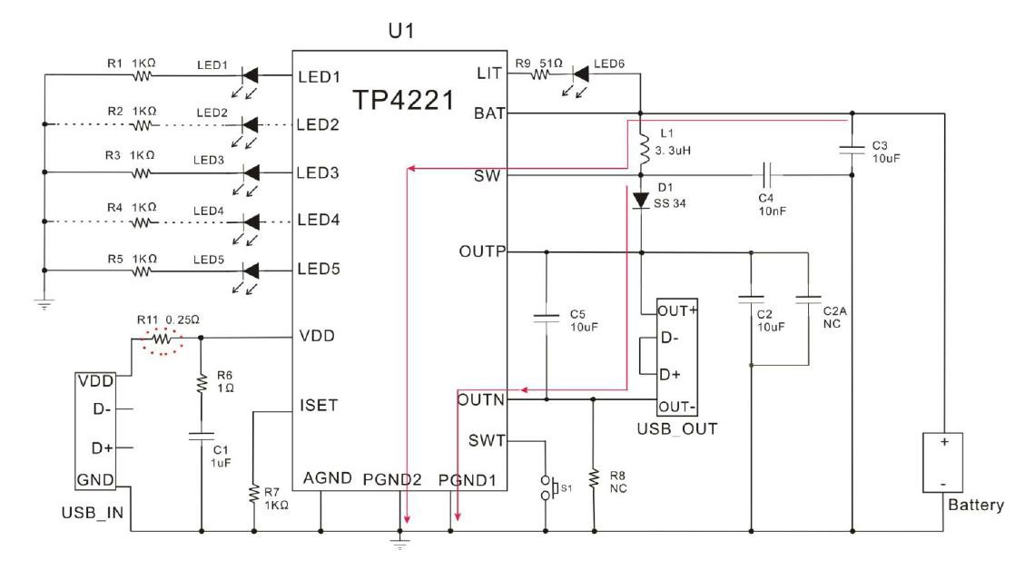
I have the thing soak testing attached directly to the LiPo output from my TP4221A/TP4221B/TP4221C – 18650 LiPo based “Power Bank” (the one that mentioned at the start of this thread). I charged the power bank up in my office, attached the modified ESP8266, flashed a web server to let me switch the on board LED on and off, and it has been running ever since.
On my Linux box I’m running..
while true; do for state in ON OFF; do wget http://192.168.7.3/LED=$state -o/dev/null ;sleep 1;done;echo -n ".";done
EDIT: Just had a rethink here… at 2500 to 2600mAh per cell and 4 cells, with the ESP spending most of its time receiving, the average current draw will be around 60 to 70 mA, so this test might last longer than I thought. In theory I may get around 166.6 hours, or about 7 days out of a single charge.
This is turning out to be even more gripping than I had expected… right up there with watching paint drying in fact ![]()
<…>
This is turning out to be even more gripping than I had expected… right up there with watching paint drying in fact
if it has an adc, could you populate the web page with its supply rail voltage?
and/or have it send a reading (to where?) every 10min, 15min, 30min and up the rate
if differs more than 5% from previous?
@ray
probmatical
stephen
ESP.getVcc()
but you also need call ADC_MODE(ADC_VCC);
I actually built a demo project yesterday using a cheap solar rechargable torch as the battery.
But I found that the 2440 Lipo button cell inside it had gone bad, and was not accepting charge ![]()
But fortunately, there was soo much space in the case I there was room for an old Nokia mobile phone lipo battery to easily fit in.
In reality, the el-chepo solar panel on the torch is onlt about 15 square cm, and seems to only output around 2.5mA into a dead short, and is not optimized for charging 3.7V batteries because its something like 6 cells, and outputs 9v off load.
But, if you leave it in the sun long enough, it does charge up, and you can push the slider swicth and turn on the little esp8266 captive portal web server inside.
PS. I tried running an ESP8266 from a normal large button cell, CR1320, but the cell is not capabile of delivering the 75mA the ESP wants, due to internal resistance and the voltage collapses – which is a shame, as i was hoping to build a button sized web server.
Well, i guess i could put a few in parallel, or I may try some nicad 60mAh cells.
i’m assuming this
battery => regulator => esp
it is a pretty picture, but is it the one we need? cell voltage against time with lines for load current
srp
I already have some test software running and displaying temperature and humidity graphs from a DHT11 so it will be easy for me to reconfigure to add the voltage as well.
<…>
This is turning out to be even more gripping than I had expected… right up there with watching paint drying in fact
Took it apart and its not 5600mAH its 2200mAH, so I have contacted the vendor to see if they will give a full or partial refund.
I know these things are often deliberatly oversold, but I could have bought a 2200mHA one for half the price and I may have actually received a 2200mha version ![]()
Looking inside it has a small PCB with a TPOWER TP4323 on it, plus an inductor and a few resistors and capacitors.
So it looks like the TP4323 is the one charge pumping the 3.7V up to 5V
http://www.sz-hxdz.com/uploadfile/pdf/2 … 213040.pdf
As far as I can see (not being able to read chinese) is that it is a dedicated 3.7V battery charge controller and 5V charge pump.
There doesn’t seem to be any external components that I could use to change its output voltage.
But my amplifier will run on 5V, so I may put the battery inside my speaker and give it a try.
Took it apart and its not 5600mAH its 2200mAH, so I have contacted the vendor to see if they will give a full or partial refund.
I know these things are often deliberatly oversold, but I could have bought a 2200mHA one for half the price and I may have actually received a 2200mha version ![]()
Update.
Plugged in the “Power bank” and it charged the 2200mAH batter until it was 4.13V on my Fluke DMM (not calibrated in years so not necessarily accurate)
During which time it flashed its red LED.
Once it had reached top of charge the LED went solid red.
If I plug a USB cable in its output nothing happens, i.e its not got an extra contacts inside the USB socket to detect if a plug is inserted, however if I measure the voltage on the output USB cable even with a DMM, the LED comes on and there is 5.08V for about 15 secs.
After about 15 secs the led goes out and the voltage drops down to a sustained 3.6V
If I plug in a real load e.g. a phone, the LED continues to stay on after 15 secs.
There is a also a small momentary push button, which seems to kick the unit into turning on its LED and producing 5V but unless there is a load the thing turns its self off after 15 secs, so I’m not sure what the button is useful for. The current detection is so sensitive I think just the capacitive load of plugging in the USB connector can on occasions turn it on.
So I’m not entirely sure the button is necessary, as it doesnt do anything like turn the output off if there is a load connected
Anyway, the next job is to stick the battery in the speaker, when I get time.
Voltage, (from my office Fluke 115 this time) 3.716 V. As you can see, this is not a very scientific test, since we are using different measuring equipment, and our device under test has been on 20 mile journey in a cliplock food box and subjected to freezing temperatures. It has also automagically logged itself off from one WiFi router and connected to another (the same SSID, different location). So far it has performed flawlessly for about 4 1/2 days without recharging. If only my mobile phone could manage that trick. ![]()
…
After about 15 secs the led goes out and the voltage drops down to a sustained 3.6V
…
<…>
…
I disassembled one down in the basement lab and took a pix, linked. I was able to easily fit an ESP8266-01 without the pin header into the space with room to spare.
Tzumi 5V Pocket Juice / about $3 surplus
Ray
I tried doing adding battery measurement as well, but I’m running directly off the lipo at the moment, just via a slider switch. I need to get some LDOs.
The wierd code is the ADC mode, as i initially tried to call it in setup, but then realised its not a function, its a macro.
Im not sure you even need the semi colon after it.
Anyway. The powerbank I have is in a nice metal box, but thats no good for a wifi device, or Bluetooth etc.
The eBay vendor is currently ignoring me, so I will see if the best option is to open an ebay dispute or give then a negative feedback.
I tried doing adding battery measurement as well, but I’m running directly off the lipo at the moment, just via a slider switch. I need to get some LDOs.
threshold="2.8";clear;while true; do voltage=$(wget http://{YOUR_IP_GOES_HERE}/ -qO- -o/dev/null |grep "Voltage"|awk '{printf "%s", $3}'|tr '\r' ' '|awk {'print $1'}) ; now=$(date);if [ $(echo $voltage'>'$threshold |bc -l) ];then echo "$now Battery OK [$voltage V]";else echo "$now Battery Low [$voltage V]";fi ;sleep 60;done
If I hold it in, there is a separate blue LED that comes on, in addition to the small SMD red led, which is mounted behind the blue LED, so because the blue LED is clear it shines out though the blue one.
If I hold the button in again, the blue LED turns off again.
Andy:
Re: what happens when it stops detecting a load. I’m not sure this is going to be much use to me, as it seems so sensitive that I think virtually any small load even a few uA may trigger it, i.e if I put an analogue volt meter to measure the current, that load is enough to keep it running ![]()
My analogue meter takes 25uA at the current deflection for 5V i.e 50uA full scale and its a 10V range reading 5V
So the load would need to be lower than that to stop it turning on its LED.
Tue Dec 15 13:07:29 GMT 2015 Battery OK [3.407 V]
Tue Dec 15 13:08:30 GMT 2015 Battery OK [3.409 V]
Tue Dec 15 15:37:46 GMT 2015 Battery OK [3.378 V]
Tue Dec 15 15:38:46 GMT 2015 Battery OK [3.378 V]
Tue Dec 15 15:39:46 GMT 2015 Battery OK [3.378 V]
Tue Dec 15 15:40:46 GMT 2015 Battery OK [3.372 V]
My rip off eBay merchant, was only willing to give me a reduction down to $9 for the power bank, and considering its only $2200mAH, i.e a fraction over the capacity of a single $1 cell, I’ve not accepted it, and have had to give maximum negative feedback and cut my losses.
It seems to be impossible to buy reasonably priced batteries on eBay. All the batteries I have bought over the years from eBay have been dodgy.
I will look around locally to compare prices with places like Target.
Edit.
Target want $39 for a 2000mhA.. Perhaps the “Variety” stores may be a better bet.
<…>
Target want $39 for a 2000mhA.. Perhaps the “Variety” stores may be a better bet.
Bear in mind that very few manufacturers produce 18650 cells in capacities >2500mAh, so pretty much anybody that says “Blah-fire battery” and has a capacity of 2700mA or greater is a bullshitter. If you want low cost sub 2000mAh or thereabouts cells, these cheap ones are fine (although I cannot vouch for ether their quality or genuine capacity, assume 1800mAh and you will probably be on the mark).
I would however go for something costing a few cents more, and with a slightly less wild claim for its capacity on the assumption that if they bullshit less, they might care a little more about their reputation.
The same goes for the power banks. Assume capacity is around 2000mA per cell. I went for the cheapest possible power bank with no cells, as I was curious to see what you would get for your money. I would not have been remotely surprised to find that at this price, the device was dangerous and blew up the first time it was plugged in. However I am pleasantly surprised, as these low cost devices look genuinely useful, shoddy workmanship aside, so long as you use laptop recovered cells or some other verifiable source, and treat them as almost disposable.
If you want a power bank that is more robust, then you will have to spend a little more, however there is a big caveat here. I have just been in to my local Sainsburys supermarket, and they were punting a 10,400mAh £25 power bank, with a well known brand name, which appears to have *exactly* the same controller in it as the cheap’n nasty device I have described.
It has one button, four blue LEDs and the same “UI” as the TP4221A, so if it looks like a duck, walks like a duck and quacks like a duck… Now I’m not suggesting for a moment that the capacity of the Saunsburys device is going to be less than the stated value, since the TP4221 is capable of charging 4 x 2600mAh cells, and this is a common enough capacity, but £25.00 is a bit of an eye watering price for a plastic box, a cheap PCB and four 18650 cells. OK Its a much better looking plastic box, but still..
However at least with this brand…

… you know exactly what they will say when you complain about the capacity.
Get The F*** outa here! ![]()
But then you know who would fill the casings with melted sewer pipes.
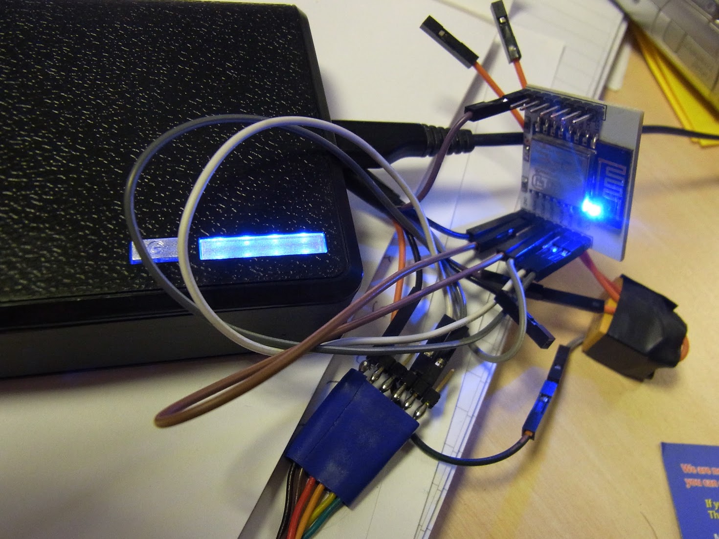
I modified the sketch to send a couple of pulses to the battery pack to switch on the “Torch LED” output, then dubbed up a 3V relay with a snubber diode and some flying leads. I attached the relevant pins to the wires I had previously run out of the battery pack. The big mess ‘O wires above is the result. (The wires exiting from the bottom of the picture go to my USB to serial converter).
When I visit the web page, now as well as toggling the LED on pin2 (the blue one ![]() ) it sends a couple of pulses to the button pin on the battery controller via a 2K resistor. Result…. I get a very satisfying click from the relay, as it latches on or off, depending on its previous state.
) it sends a couple of pulses to the button pin on the battery controller via a 2K resistor. Result…. I get a very satisfying click from the relay, as it latches on or off, depending on its previous state.
The ESP8266 GPIO cannot drive a 50mA relay (they are limited to 12mA source, 20mA sink), but the Torch LED output pin on the battery pack can.
A sequence of 300ms LOW, 300ms HIGH, 300ms LOW and back to HIGH seems to be the sweet spot to make it work 100% of the time.
#include <ESP8266WiFi.h>

ADC_MODE(ADC_VCC);

const char* ssid = "your.ssid";

const char* password = "your.password";
int relayPin = 4; //GPIO4
int ledPin = 2; // GPIO2
WiFiServer server(80);
void setup() {
Serial.begin(115200);
delay(10);
ESP.getVcc();
// Start up, switch on the LED and set the relay toggle pin HIGH
pinMode(ledPin, OUTPUT);
digitalWrite(ledPin, LOW);
pinMode(relayPin, OUTPUT);
digitalWrite(relayPin, HIGH);
// Connect to WiFi network
Serial.println();
Serial.println();
Serial.print("Connecting to ");
Serial.println(ssid);
WiFi.begin(ssid, password);
while (WiFi.status() != WL_CONNECTED) {
delay(500);
Serial.print(".");
}
Serial.println("");
Serial.println("WiFi connected");
// Start the server
server.begin();
Serial.println("Server started");
// Print the IP address
Serial.print("Use this URL to connect: ");
Serial.print("http://");
Serial.print(WiFi.localIP());
Serial.println("/");
}
void loop() {
// Check if a client has connected
WiFiClient client = server.available();
if (!client) {
return;
}
// Wait until the client sends some data
Serial.println("new client");
while (!client.available()) {
delay(1);
}
// Read the first line of the request
String request = client.readStringUntil('\r');
Serial.println(request);
client.flush();
// Match the request
int value = digitalRead(ledPin);
if (request.indexOf("/LED=ON") != -1) {
digitalWrite(ledPin, LOW);
value = LOW;
toggleRelay();
}
if (request.indexOf("/LED=OFF") != -1) {
digitalWrite(ledPin, HIGH);
value = HIGH;
toggleRelay();
}
// Set ledPin according to the request
//digitalWrite(ledPin, value);
// Return the response
client.println("HTTP/1.1 200 OK");
client.println("Content-Type: text/html");
client.println(""); // do not forget this one
client.println("<!DOCTYPE HTML>");
client.println("<html>");
client.print("Led pin is now: ");
if (value == LOW) {
client.print("On");
} else {
client.print("Off");
}
client.println("<br></br>");
client.print("Battery Voltage: ");
int batteryVoltage = ESP.getVcc();
client.print(batteryVoltage / 1000);
client.print(".");
client.println(batteryVoltage % 1000);
client.println("<br></br>");
client.println("Click <a href=\"/LED=ON\">here</a> turn the LED on pin 2 ON<br>");
client.println("Click <a href=\"/LED=OFF\">here</a> turn the LED on pin 2 OFF<br>");
client.println("</html>");
delay(1);
Serial.println("Client disonnected");
Serial.println("");
}
void toggleRelay() {
digitalWrite(relayPin, LOW);
delay(300);
digitalWrite(relayPin, HIGH);
delay(300);
digitalWrite(relayPin, LOW);
delay(300);
digitalWrite(relayPin, HIGH);
}
News on my battery project…
Boost converts arrived yesterday, and work well, right down to 3.7V.
Unfortunately I seem to have killed one boost converter. Not sure how. Possibly it didnt like a loose connection on its input, from the 3.7 v power bank battery ![]()
I better order some more, boost converters, as they will boost 5V up to about 2.5A input, up to 12V at about an amp, which may come in handy
Power bank unit is proving to be virtually useless. It doesnt like the influx of current to the 470uF cap on the input of the boost converter, so trips out and immediatly stops outputting on its 5V line.
I did briefly run the boost converter directly from the 3.7V battery of the power bank, but this is not a lot of use, as It does not have any limit on the battery discharge and I will poison the battery.
So…
It looks like I need to design and build a custom battery charge / discharge controller, for my 11.1v pack. In fact I may reconfigure the battery pack to be around 18V as the main issue is the current required by the audio amp, and the higher the voltage the lower the current I need.
At the very least I need to stop the battery going totally flat.
I used a higher power boost module that uses the XL6012 rather than the XL6009, I have some on order like the ones in your photo, but they have not arrived yet.
The XL6012 looks to be a decent device, and his higher current than the XL6009 but I can only find one type of board on eBay using the 6012 and consequentially its a lot more expensive than the smaller boost module, because of the lack of competition
In reality, as i can only get up to about 1A at 5V from a USB charger, its pointless using the XL6019 board, and the XL6012 will be adequate to perform a slow charge of the 18V lipo stack.
What tends to let them down is the quality of the capacitors, often they are under spec’d 85C and too low a working voltage to allow the full range of the regulator to be used, however you can swap these out for better ones if needs be. I think it is also possible to hack them to produce an inverted output (i.e. -ve rail rather than +ve), but take care with the polarity of any caps, if you attempt this.
EDIT: Actually the data sheet gives a simple way to achieve a dual supply using a center tapped transformer. You could probably use an off the shelf component for that. Failing that, it would should be relatively simple to wind your own, 47uH 4A primary 2x 47uH dual secondaries.
http://www.ebay.com.au/itm/3-x-PCB-for- … Kf2lduIFmg
I wonder if they will really handle 3.5A, as that would be enough, but I don’t trust eBay specs ![]()
Edit.
Actually there are more on AliExpress
e.g.
http://www.aliexpress.com/item/Free-shi … eb201560_1
But its hard to tell if they are both a charge controller and discharge protection or just discharge protection
In Europe it’s a wise idea to buy 18350/18650 cells from “electronic cigarette” shops. They often have good deals with legit major brand products (samsung, sony, panasonic…). One example (german): http://www.vapango.de/search?sSearch=18650
Even on aliexpress you can buy 18650 cells IF you stay realistic. I’ve ordered these ones and they work good for a half an year:
http://tinyurl.com/jj4qunc (You can see it on the overall feedback score, that’s a legit product)
Not sure how fast they switch, that would probably depend on the speed of the optoisolator, but unless you need multi megaherz performance, they will be suitable for most tasks. They also consume a great deal less power than a conventional relay, however you can’t switch AC mains voltages with them directly, for that you would need a conventional relay (or a solid state relay).
<…>
Power bank unit is proving to be virtually useless. It doesnt like the influx of current to the 470uF cap on the input of the boost converter, so trips out and immediatly stops outputting on its 5V line.
<…>
The 470uF is part of the boost converter input. I suspect the boost converter may work without it, but would be less efficient as it probably relies on a good low impedance power supply.
The 470uF is part of the boost converter input. I suspect the boost converter may work without it, but would be less efficient as it probably relies on a good low impedance power supply.
I finally got around to testing the 3 cell lipo charger I bought off eBay.
http://www.ebay.com/itm/400789255418
I ran it from my bench PSU, and it didn’t work in the way I’d expected ![]()
On the case it has the input voltage listed as 10.0V to 15.0V, which makes sense as its has to be able to charge a 11.1V pack to its max charge voltage.
However, when I connected it to my bench PSU and turned up the voltage from zero (with a ammeter connected to the +ve side of the battery), the PSU started to have to deliver a lot of current as soon as the voltage got above around 2.5V. And my PSU maxes out at 925mA at around 3.6V input (though its supposed to deliver an amp !)
I’ve no idea what would happen if I collected it to a larger source of current e.g. a 12V car battery. I presume that there is some sort of internal current limiting in the unit. The eBay listing shows 800mA, but this must be per cell, as its already taking more than that at 3.6V.
I suspect what it has inside is 3 individually isolated boost converters, as charges the cells even when the input is less than an an individual cell voltage (3.7V)
Anyway.. I guess this saves the need for a separate boost converter, but ideally, I need a way to change the current limit, as I was hoping to do more like a trickle charge from USB at a few hundred mA, and not need to plug it in to a high power USB charger e.g. one of the 2A ones.
(actually even 2A would not be enough if it limits to 800mA per cell (3 cells).
Charging this 11.1V battery in my speaker / amplifier unit is proving to be more complex than I though ![]()
,<…>
Charging this 11.1V battery in my speaker / amplifier unit is proving to be more complex than I thought
Joke apart, I’m still waiting for my first 18650s to arrived from “slow-boat”.
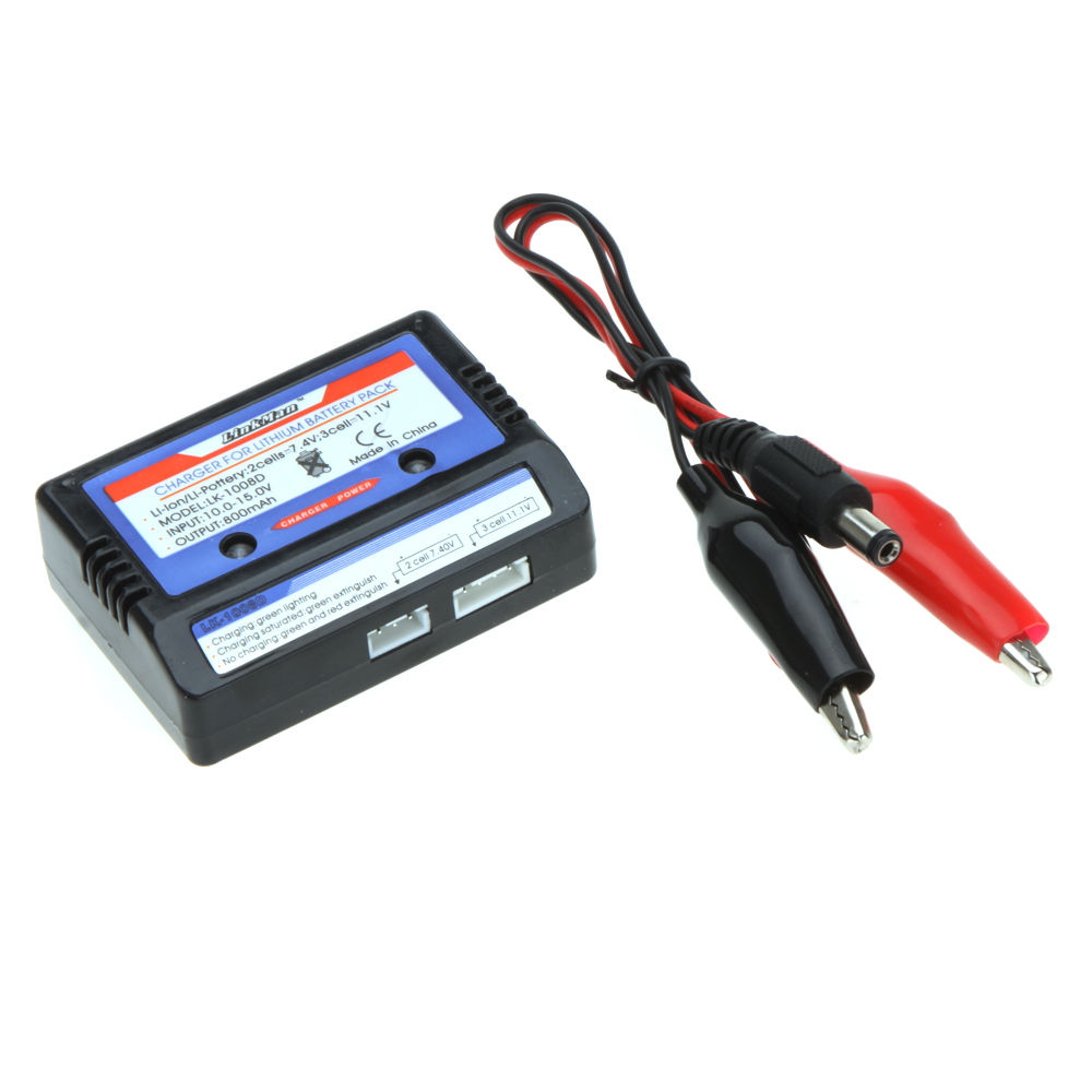
I have already received this charger : http://www.ebay.ca/itm/331685404010?_tr … 2749.l2649
I hope I won’t ignite any fire in my house when I will place the 18650s into this charger …
srp
I suspect that there are individual lipo charging circuits that are coupled together, so there is no balance charging going on. The charger is likely just charging until all cells reach a set voltage regardless of the fact that one or 2 cells might already be above that voltage.
I think you are right ![]()
One of my 3 sets of cells was not charging as fast as the other two ( its has 3 lots of 2 cells in parallel).
So i cut the pack apart and put the 2 dodgy cells in series, to form the lower 2/3 of the battery, however it carried on charging the originally good cells to 4.25V albeit at less current , 150mA, than it was giving the 2 dodgy cells.
So i turned it off, and I will individually charge the 2 dodgy cells to see which one ( or both) is actually duff.
I suppose they didnt say it was a balanced charger. It was just my presumption as it has a wire to each cell individually.
I’m not sure its any better than just giving the 3 cells in series a current limited slow charge to 12.6V ( because I’ charging from 5v usb, I dont have much current in the first place ( from the 5V input if its plugged into a computer instead of a charger)
Anyhow, I believe the charger you have is going to send 4.2V to each cell with some crude current limiting. If I get a moment over the holiday weekend, I will crack the charger I have and look at the circuit. I just know that Lipo stiff gets pretty contentious, so it’s hard to tell how bad these little chargers really are (people trash my clone for A. Being a straight rip off and B. Being terrible because of calibration). Mine has worked fine so far; I think most of the hate is directed at the B6AC with a built in power brick that’s terrible, and also for arly clones that didn’t implement the extra features (USB serial out and temp probe) or proper charging in NiCD and NiMH packs.
http://www.ebay.ca/itm/4pcs-3-7V-18650- … 1887058655
Surprisingly, they arrived already charged …
But about, the charger that I had already received, http://www.ebay.ca/itm/331685404010, I’m not sure I will trust it : after placing the batteries in it, press PowerOn switch, LEDs turn on (that’s how I discovered that batteries were already charged), but pressing again the button, I couldn’t turn it off again. I had to open the casing and remove batteries … ![]()
It was not hook-up of charge neither to provide power to some devices (I don’t want to ignite a fire yet), simply plug the batteries into it.
There internal SMT LEDs seen thru plastic window, four of them, normally 1 LED per Battery, but strange : all batteries are in parallel, so how could it be sensed individually ? Looking at the chip that handle all those charging capabilities, it has been “paper sanded”
There another 3mm LED near the USB power input, when I recycle button press, it is toggling ON/OFF every two button press, but the four SMT leds are never power OFF. Of course, there is no User Manual …
Yes, this is identical to mine.
(When threads are becoming huge and old, I have tendency to forget to read them back from the beginning
So, now, I won’t worry any more about ignite a fire … ![]()
Yes, this is identical to mine.
(When threads are becoming huge and old, I have tendency to forget to read them back from the beginning
The fire risk depends more on the quality of the LiPos I would suggest. If they are “BangGood SureFire 96000mA” then I suspect there may be a slightly higher risk than the Sanyo ones I extracted from a laptop battery.
<…>
What do you think of those ? I can’t find any marking other than GTF TR-18650 Li-ion,
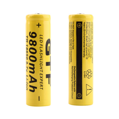
Also, I’m waiting some other from “slow-boat”, marking on those seems to be LS-18650 :

I’ve given up on using the 3 cell, charger I bought, as although it seems to be able to charge 11.1V from 3.3V ( less).
But it seems to overcharge the batteries, as two of them got to nearly 4.3v because one of the cells in the pack was not as good as the other 2.
As I need to charge from the USB on a PC, I’m limited to around 200mA at 5V, which when boosted up to 12V, equates to only around 50mA.
Or I may be able to detect a high current charger and switch this to 1A at 5V, which would be around 300mA to the pack.
I have found the best way to do this is to put a current regulator on the output of my boost converter, because although it also works if I limit the current on the input, As I only have 5V comming in, there is a not enough voltage to adequately run a LM317 as a current regulator, as it needs a minimum of 1.5V to regulate, which leave too little to run the boost converter.
Hence its better to boost to about 13v, then when I get a drop of 1.5v I can still charge the lipo’s to 11.5V and limit the current to a max of 50mA so that I dont load the 5V side too much
What do you think of those ? I can’t find any marking other than GTF TR-18650 Li-ion,
Also, I’m waiting some other from “slow-boat”, marking on those seems to be LS-18650 :
What do you think of those ? I can’t find any marking other than GTF TR-18650 Li-ion,
Also, I’m waiting some other from “slow-boat”, marking on those seems to be LS-18650 :
(in those case, it is not the sellers who are liars, but the fabs, such GTF, UltraFire, etc)
(in those case, it is not the sellers who are liars, but the fabs, such GTF, UltraFire, etc)
The highest you can get (for real) is below 4000mAh, with most of the reliable, branded 18650 in the 3000-3500mAh range
Most of the no-name cheap Chinese batteries are, like Andy says, 800 to 2000mAh. Rarely you’ll find anything higher
It is some kind of scandal like Volkwagen scandal … ![]()
It is some kind of scandal like Volkwagen scandal … ![]()
srp
But all those becoming much technical …
I like technicals when it digital, but never really digested them when analog.
At school in early 198x, I was saying “5V is a civilized voltage”
So, for those 18650 batteries, I will play with them … Fear of ignite fire came back … ![]()
At least in the Hobby world, the C ratings don’t tend to get over-inflated too much. Some of the packs even list a peak/burst and an average C rating as some setups can easily overdraw a battery and cause a brownout to the Flight controller (usually resulting in BAD things like a mangled pile of parts).
I would likely be more tempted to power projects from Quadcopter batteries since I know them pretty well and have all the equipment for easily charging packs (not to mention a pile of spare batteries laying around).
http://www.aliexpress.com/item/10Pcs-in … 13083.html
I have bought at least 50 of these PKCELLs and always tested the capacity of each cell individually 4.2V -> 3.0V @0.5A. So far, I never had any cell below the nominal 2200mAh, most range between 2250 and 2350mAh. I usually buy when they have a 30% or higher sale (for which I never had to wait more than a week to happen), so the price I paid was always between $19 and $22 per lot of 10.
I just am not that familiar with the 18650 cells. I would imagine their Current ratings are in line with the intended use: Laptop batteries. and I agree about charge/discharge rates. The accepted rule for 3S Hobby Lipo packs is 1S (Charge a 2700Mah pack at 2.7A), however I usually charge them at a lower rate, especially the first time when I have to discover what the true capacity is. I suppose I should get busy and build a battery temp probe so I can feel a little better about that 1S rate (it’s not like it’s hard since I have all the parts laying around…
I just am not that familiar with the 18650 cells. I would imagine their Current ratings are in line with the intended use: Laptop batteries. and I agree about charge/discharge rates. The accepted rule for 3S Hobby Lipo packs is 1S (Charge a 2700Mah pack at 2.7A), however I usually charge them at a lower rate, especially the first time when I have to discover what the true capacity is. I suppose I should get busy and build a battery temp probe so I can feel a little better about that 1S rate (it’s not like it’s hard since I have all the parts laying around…
http://www.ebay.com/itm/Portable-USB-Mo … 4647912f14
I can’t complain for $.70 and free shipping and I got a bunch of 5800mAh 18650 for like $.36 a piece with free shipping. So what can I say for slightly more than $1 plus the cables. I got them for like $1 a piece. These can supply a max of 1A which is far more than I would need anytime soon.
Only gotcha was it was purple. My wife saw it on the table and knew what it was and snatched it up for herself. ![]() lol At her work inside it drains her phone terrible. So needed it for emergency. Oh well, it was a feather in my cap for her so she doesn’t complain any about my odd purchases. lol Just had to order myself more now. Keep this up I know what I’ll get everyone for Christmas this year. lol
lol At her work inside it drains her phone terrible. So needed it for emergency. Oh well, it was a feather in my cap for her so she doesn’t complain any about my odd purchases. lol Just had to order myself more now. Keep this up I know what I’ll get everyone for Christmas this year. lol
My next though was for something smaller. Everyone seems to be pointing to LiPo power. But then I started down another rabbit chase about supercaps. i just started down this trail so not sure if they can be used solely as power or like in this article:
http://www.digikey.com/en/articles/tech … nsor-nodes
I’d love to see some pics of others that have powered their projects in various ways.
Michael
<…>
But then I started down another rabbit chase about supercaps. i just started down this trail so not sure if they can be used solely as power or like in this article:
I’d love to see some pics of others that have powered their projects in various ways.
Michael
Might be something for a good experiment to try. They’re cheap enough I can buy one and see. I already have a couple of voltage converters I had planned on using. This way I could see what the super-cap does to the regulator. I can see how the super-cap would be great for when there are spikes in current. Don’t know until you try or until you smoke something. lol
Michael
Michael
50PCS 3.7V 5800mAh 18650 Li-ion Rechargeable Battery For Flashlight From USA
At $.36 a piece I can’t complain. One already went to my wife’s emergency phone battery pack. If anyone wants any I’ll be glad. Just help me pay shipping. Unless I get wild with projects and have a lot of Christmas presents to give away it’s unlikely I’ll use all 50 for a while. If you do want some PM me.
Michael
Ray
Ray
<…>
It would be handy to have around and also work for testing supercaps as well.
<…>
Michael
… cheap batteries with massively overstated capacities are cheap for a reason. The tiny cells inside the ones in the video cost a few cents each in large volumes, so converting them in to 18650 cells and charging a dollar for them makes a big profit. Those thin cylindrical cells are used in disposable e-cigarettes amongst other things.
50PCS 3.7V 5800mAh 18650 Li-ion Rechargeable Battery For Flashlight From USA
Michael[/quote]
50PCS 3.7V 5800mAh 18650 Li-ion Rechargeable Battery For Flashlight From USA
Michael
The big question is… what is their actual capacity? If they come anywhere close to 5800mAh I’ll be very tempted to order some. My quick back of the envelope calculation suggests that fully charged, at 5800mAh per cell, those 50×18650 cells should manage to store about 1kWh (3.6 megajoules) or roughly the energy of 150ml of unleaded petrol, so don’t go shorting them out
Can anyone recommend a quality charger for 18650 liPo cells. I’d like to charge 6 at a time if possible for this battery pack
https://www.ebay.com.au/itm/Mobile-Powe … 4EE1577802
but I want to be confident the cells are being individually monitored and charged correctly, because of the various posts in this thread which warn of poor power distribution among multiple cells in cheap devices.
I’m also interested to find if there’s a simple device which I can put inline in the power supply to my time lapse camera rig which will disable the supply from my 6cell LiPo battery pack, once the charge reaches the lower safety limit of LiPo discharge. I’m a novice to electronic components but it seems a simple concept to me.
Cheers
Stack
[Sdack – Fri Oct 27, 2017 3:30 am] – Can anyone recommend a quality charger for 18650 liPo cells. I’d like to charge 6 at a time if possible for this battery pack
Serial or parallel?
For parallel you need a parallel loading adapter.
You may buy the most cheap Imax B6 / Clone you can find.
The power is limited to 50W.
But there is an OpenSource project: Cheali Charger.
Originally designed for chargers based on an ATMEGA32 it supports ARM-based chargers also.
You can find CHeali charger on github
If you need more power you may get a more powerful model, up to 2x200W.
But be careful, not all are supported (no ATMega32, Novoton ARM), plz refer the hardware section on github first.
The Lowest Quality LION (LQL) charger I use with 4×18650 cells from an old notebook:
1. set the lab power supply at 16.75V (4×4.2V),
2. connect the 4×18650 pack via 4.7ohm/5Watt resistor to the power supply.
The resistor will limit the current to around 1A with discharged cells (4×3.5V), it will not create a constant current, however (the current will drop linearly to almost zero when charged). When “charged” the laboratory power source will maintain the “constant” voltage.
Use at your own risk, no warranties of any kind are provided
This is a fairly simple LiPo charger which works:
https://www.rcgroups.com/forums/showthr … -Schematic
I added a 3A diode in the + rail:
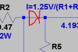
- Added Diode.JPG (14.53 KiB) Viewed 385 times
It has voltage and current limiting.
I set the voltage before connecting the batteries.
Then turn the current limit right down, and connect the batteries, and then increase the current to perhaps C/10 or whatever I think the cells will take
Then the bench PSU limits to that current until it gets to the desired max voltage
