http://www.stm32duino.com/viewtopic.php?f=28&t=490
it show the same as old picture when I was bought but when I received that sent to me is a new version of board.

- P_20170822_160309.jpg (65.49 KiB) Viewed 1274 times
tucked away on their page is this link
http://microelk.azurewebsites.net/STM32 … 32_CZ_mini
really, really interesting page & it has a raft of listings, including a CubeMX ioc file, uses an earlier version of CubeMX, but it migrates to current without issues.
stephen
immediately visible through the static bag, 2 off 4×2 connector’s
<edit1>
i’m pessimistic – and it’s back to find the compatible tft mode – 32 pin with pins, actually skt ones are required as well, as i’ve similar blue boards, but with header 32 pin
</edit1>
stephen
I still testing the SDIO using this lib but it not working on F1 board.
http://www.stm32duino.com/viewtopic.php … t=sdio+lib
this library only work in SPI mode in F1 board. ![]()
PS:
don’t download the generic_boot20_pe5 because the button is pull up set to the PD2 which is used for SDIO CMD pin.
[poiuycat – Fri Sep 01, 2017 3:03 pm] –
I still testing the SDIO using this lib but it not working on F1 board.
http://www.stm32duino.com/viewtopic.php … t=sdio+lib
That library is designed for F4 boards, not for F1.
I think Victor tried/wanted to port it to F1, I don’t know how much he did.
I don’t own any F1 board which has SDIO, so I cannot develop/test SDIO for F1.
good luck
OOOps !!! I thought was zmemw16 , sorry …. ![]()
at one time our office had 5 chris + 7 steve/stephen, phone calls – you want chris ? you want steve ?
closely followed by which one ? ![]()
if anyone spots a suitable display, yell loudly please
stephen
POIUYCAT:
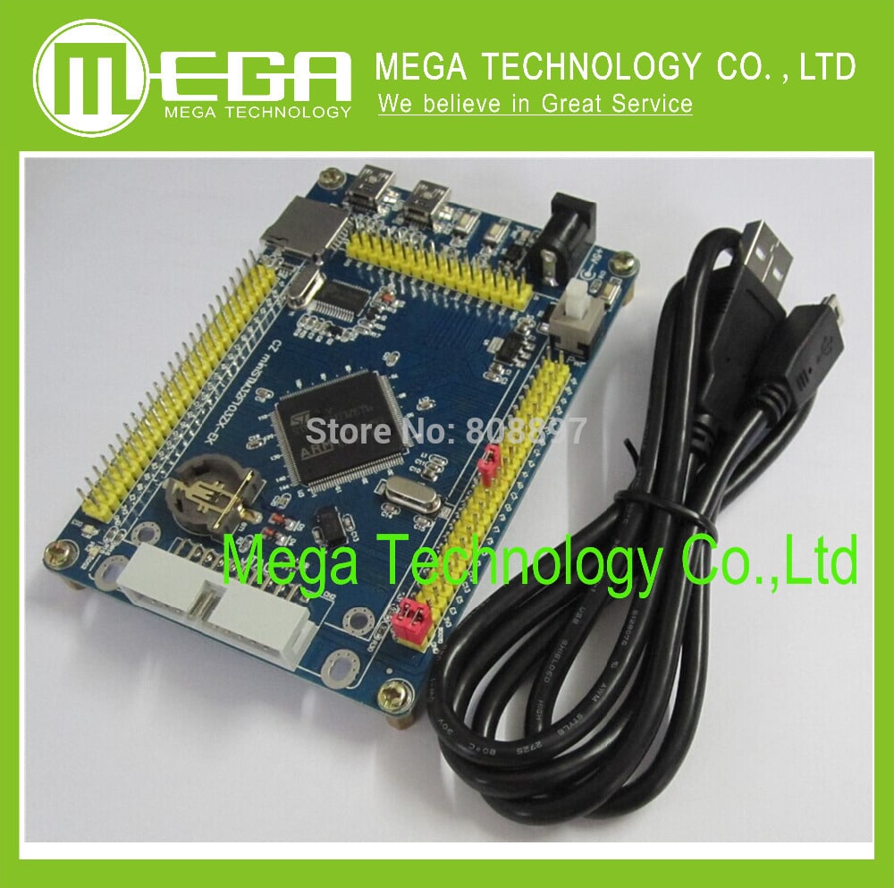
The item you sent is not same as photo.
Please provide the NEW board datasheet, schematic link that I can download.
thanks.
Electronic tycoon.
What’s the difference, please?
POIUYCAT:
red circuit mark [picture with mark]
Electronic tycoon.
What’s the problem?
POIUYCAT:
That a few pin have been changed.
i don’t have time to do the Reverse engineering , just send me the schematic !! OK
BTW please update the new photo that you selling .
Electronic tycoon.
J1 and J2 IO mouth extension with 2.54 mm gap insertion
STM32F103RBT6 internal resource profile:
The cortex-m3 kernel / 72MHz main frequency / 128KB FLASH / 20KBRAM / 4 16-bit timer / 2xSPI / 2xI2C / 3xUSART / 1x USB / 1x CAN / 48 IO / 16 channels 10 bits ADC
The CPU on board:
CPU: STM32F103RBT6
Packaging: LQFP64
The Controller Family/Series: STM32F
FLASH memory FLASH: 128KB
Data storage capacity, RAM: 20KB
Timer: 4
Encapsulation form: LQFP
Operating temperature range: – 40 ° C to + 105 ° C
Stitches: 64
SVHC (high concern material) : No SVHC (18-jun – 2010)
Working temperature: lowest to 40 ° C
The highest working temperature: 105 ° C
Serial communication: 2xSPI, 2xI2C, 3xUSART, USB, CAN
32 digits:
Device label: (ARM Cortex) STM32
Storage type: FLASH
Timer number: 16
Package type: stripping
Interface type: CAN, I2C, SPI, UART, USB
Clock frequency: 72MHz
Number of analog transformers: 16
Maximum power supply voltage: 3.6 V
Minimum power supply voltage: 2V
Chip label: STM32F103RB
Surface mounting device: surface mounting
Input/output line number (input/output IO) : 49;
Hardware introduction:
A, battery seat;
B, USB 2.0 full speed interface;
C, power switch;
D, 20 foot standard JTAG mouth;
E, two user keys;
F, a reset button;
G, DB9 serial port (imported SP3232 IC),
H, all IO ports are raised – 2.54 mm spacing pins,
Board size: 91.9 mm X 67.3 mm;
Shipping list:
1. STM32F103RBT6 core plate;
2. USB print wire (for USB communication and power supply)
I order the CZ mini STM32F103VE-EK
end up the sent me the STM32F103RBT6 datasheet !!!!!! WTF
I know they just a reseller if they don’t have schematic just said don’t have.
and then they always do is copy and paste answer. ![]()
![]()
![]()
those customer service totally dunno what diff STM32F103RBT6 and STM32F103VE !!
I want schematic why they sent me datasheet !?!? ![]()
PS: can I request for refund ?! ![]() PCB Layout is not as described.
PCB Layout is not as described. ![]()
srp
[stevestrong – Fri Sep 01, 2017 3:08 pm] –[poiuycat – Fri Sep 01, 2017 3:03 pm] –That library is designed for F4 boards, not for F1.
I think Victor tried/wanted to port it to F1, I don’t know how much he did.
I don’t own any F1 board which has SDIO, so I cannot develop/test SDIO for F1.
I went over the code and RM checking the differences, but that was it so far. The base address for registers needs to be changed, all registers match. DMA functions need to the changed whereever they are used since the F1 DMA is difference (no FIFO, no streams…) Bulk of the code except for the DMA parts should work exactly as it is since the peripheral itself is identifical, even the same bugs… ![]()
I have to free out PA13,Pa14,Pa15 from SWDIO.
RCC->APB2ENR |= AFIOEN;
AFIO->MAPR = SWJ_CFG(SWJ_CFG_SW) ;
![]()
[victor_pv – Sat Sep 02, 2017 2:58 pm] –[stevestrong – Fri Sep 01, 2017 3:08 pm] –[poiuycat – Fri Sep 01, 2017 3:03 pm] –That library is designed for F4 boards, not for F1.
I think Victor tried/wanted to port it to F1, I don’t know how much he did.
I don’t own any F1 board which has SDIO, so I cannot develop/test SDIO for F1.I went over the code and RM checking the differences, but that was it so far. The base address for registers needs to be changed, all registers match. DMA functions need to the changed whereever they are used since the F1 DMA is difference (no FIFO, no streams…) Bulk of the code except for the DMA parts should work exactly as it is since the peripheral itself is identifical, even the same bugs…

ya, I did try to do so, that F1 using individual register and F4 using array !!! ![]()
would it be possible to split the dma parts out as a new library or is it too tightly coupled or even as a guide on how to add it ?
stephen
[zmemw16 – Sat Sep 02, 2017 3:16 pm] –
if i understand the various spi threads correctly; spi now has dma capability.
SPI has DMA functions for well over a year.
To answer that, the DMA code was already a functional generic library by Leaflabs, we just used that library to add use DMA with the SPI.
I have also used the DMA library for the i2s driver, there is samples of code here being used for GPIO, and Steve has used it (the F4 version) in the SDIO code.
The SDIO code from Steven is written for the F4 DMA library, which is slightly different because the DMA peripheral is different. So to get the SDIO library working in the F1, one needs to do 3 things:
1.-In the header file, change the base address for the registers, since the SDIO peripheral is the same in the F1 but with a different base address.
2.-Anywhere where speed is calculated, take in account the different speed at which the MCU runs in the F1 (72 vs 168 normally).
3.-In the read and write functions, which use DMA, change the DMA functions to use the F1 dma library (not a big deal, since the are close, just not exactly the same)
I compared the SDIO peripherals page by page between the F1 and F4 and they are exactly identical, except for the base address, so I am 100% sure that’s the only change regarding registers.
correct, it was the idea of separating the dma functionality from the spi and making it generally available.
so my boards arrived, both with the esp & nrf 8pin connectors.
anyone seen an updated schematic ?
stephen
i have the microchip spi demo board connected, 7 devices.
currently the spi is A5,A6 & A7 with CS signals connected PE8 to PE14
anyone seen a new schematic for this version ?
stephen
i think the outside 22 hrs out of 24 feline may have forgiven me for the dose of frontline to the back of her neck. she stuffed herself on top of the book shelves, dropped down 2ft and then another 2ft, strolled across the wobbly bed tray/stand i use as a desk.
groomed herself for a while and went to sleep on my chest. observing my screen past a rear paw/leg in my face can be an issue.
abnormal for her, exceedingly so. twice in maybe 9 months. normal is i lift her from the bookshelves, she;ll groom, maybe stay/sleep a bit, then she’ll bounce off. last week she flounced off me after sliding my chest & supporting arm in her sleep.
[zmemw16 – Sun Sep 24, 2017 2:57 am] –
….i think the outside 22 hrs out of 24 feline may have forgiven me for the dose of frontline to the back of her neck. she stuffed herself on top of the book shelves, dropped down 2ft and then another 2ft, strolled across the wobbly bed tray/stand i use as a desk.
groomed herself for a while and went to sleep on my chest. observing my screen past a rear paw/leg in my face can be an issue.
abnormal for her, exceedingly so. twice in maybe 9 months. normal is i lift her from the bookshelves, she;ll groom, maybe stay/sleep a bit, then she’ll bounce off. last week she flounced off me after sliding my chest & supporting arm in her sleep.
We are increasingly getting Bots who post text like this, which are valid texts but not related or useful in terms of the discussion.
To prevent your posts being marked as spam, its best if you omit posting these unrelated paragraphs
stephen
[zmemw16 – Sat Sep 23, 2017 4:31 pm] –
i swear it made sense when i typed it.
correct, it was the idea of separating the dma functionality from the spi and making it generally available.so my boards arrived, both with the esp & nrf 8pin connectors.
anyone seen an updated schematic ?stephen
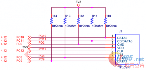
it same as old schematic just change button and add new socket.
http://wiki.stm32duino.com/images/4/4d/ … ematic.pdf
ESP-1 WIFI module
Pin PC3 — Reset
Pin PA0 — CH_PD
Pin PB11 — ESP RX
Pin PB10 — ESP TX
Pin PC1 — GPIO 0
Pin PC0 — GPIO 2
NRF24L01 wireless module
Pin PE2
Pin PB5
Pin PC13
Pin PE4
Pin PB3
Pin PB4
PS: I never try out the ESP-1 WIFI yet , not sure that 1117 is power enough to drive the ESP with LCD screen or not !!!
it cheaper that stm32F103VEt6 100 pin $ 12.61 with shipping fee
https://www.aliexpress.com/item/NEW-ARR … 0.0.TvFxMZ
- ministm32f103zet6.pdf
- (233.16 KiB) Downloaded 54 times
there are a lot of variations in these boards, header or socket for the tft and of the eprom & flash presence.
srp
