I’m an IT bod with over 20 years experience in various industries, I’m an average coder who has mainly been cutting scripts and not touching any low level languages. I’ve not touched electronics or C (never mind c++) since Uni, so I’m having to rapidly assimilate a lot of information – fortunately I still remember most of the grounding I learned.
I’m building a system that can read automotive analogue sensors and display the output on OLED screens.
It’s using OLED screens because they are easy to read in bright light, darkness, and when not directly facing them.
This started life as a set of gauges for my Land Rover which I take off road, but it’s just as applicable to any vehicle
So far I’ve included code for:
* Bosch temperature sensors NTC M12 0 280 130 026 (coolant, oil, gearbox temp)
* Generic 4 bar pressure sensors (boost pressure)
* Simple normally closed alarm switches (coolant level etc)
* K-Type thermocouple – using a MAX31856 IC (Exhaust gas temp)
* Generic oil/air pressure sensors (0-100psi, suitable for oil pressure)
* Roll and Pitch (using ADXL345 accelerometer)
* Compass heading (using HMC5883)
I’m looking to bundle OBD2 data into the mix by means of a chinese ELM327 dongle (it has an HC06 bluetooth module in the box), coupled with an HC05. There’s a fairly sizable amount of pre-written code available for Arduino to grab the data via that pairing, given that the hc05 is uart driven I figure it ought to work on STM32. Fingers crossed.
I need to expand user interaction so that warning values can be configured, and so that the ordering of the sensors can be set. This is probably going to mean I need some form of storage, be that eeprom, eeprom emulation, or an SD card. SD card would be the preference because then I can include a data logging option).
Life started on an Arduino Nano clone, but this was rapidly outgrown from a GPIO, flash, & sram perspective. Not wanting the footprint of an Arduino Mega I looked about and found this forum.
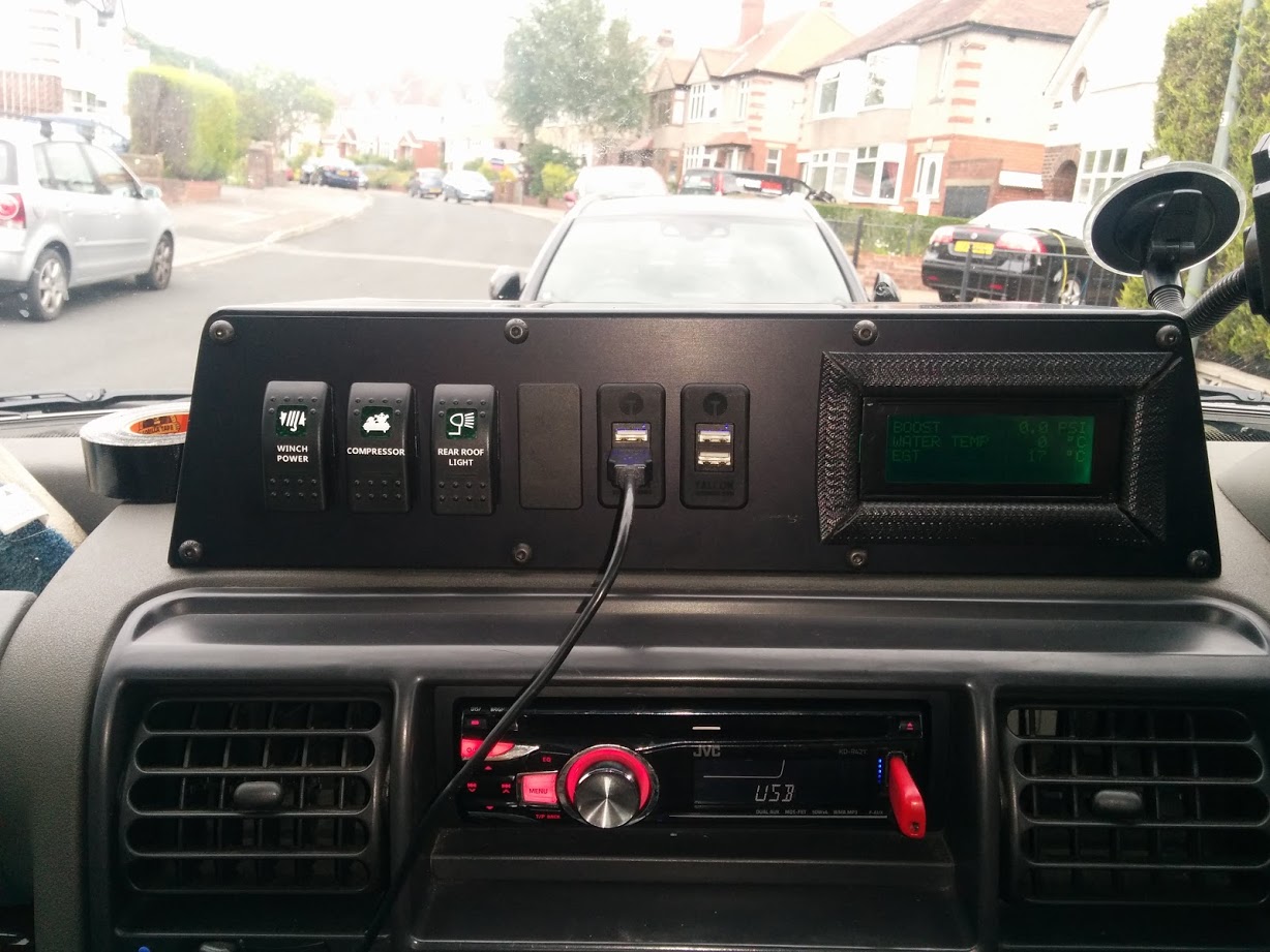
Originally I had an off the shelf system in the car, it was quite expensive, and not easily read (LCD screen) – I contacted the vendor to see about changing the display for an OLED and he wanted £250. After opening the box and finding an Arduino in it, I decided I could make my own for quite a lot less money.
Pic of the original:
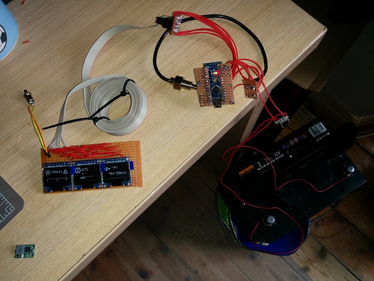
Pic of my original Nano driven replacement just prior to install – it’s a bit Heath Robinson:
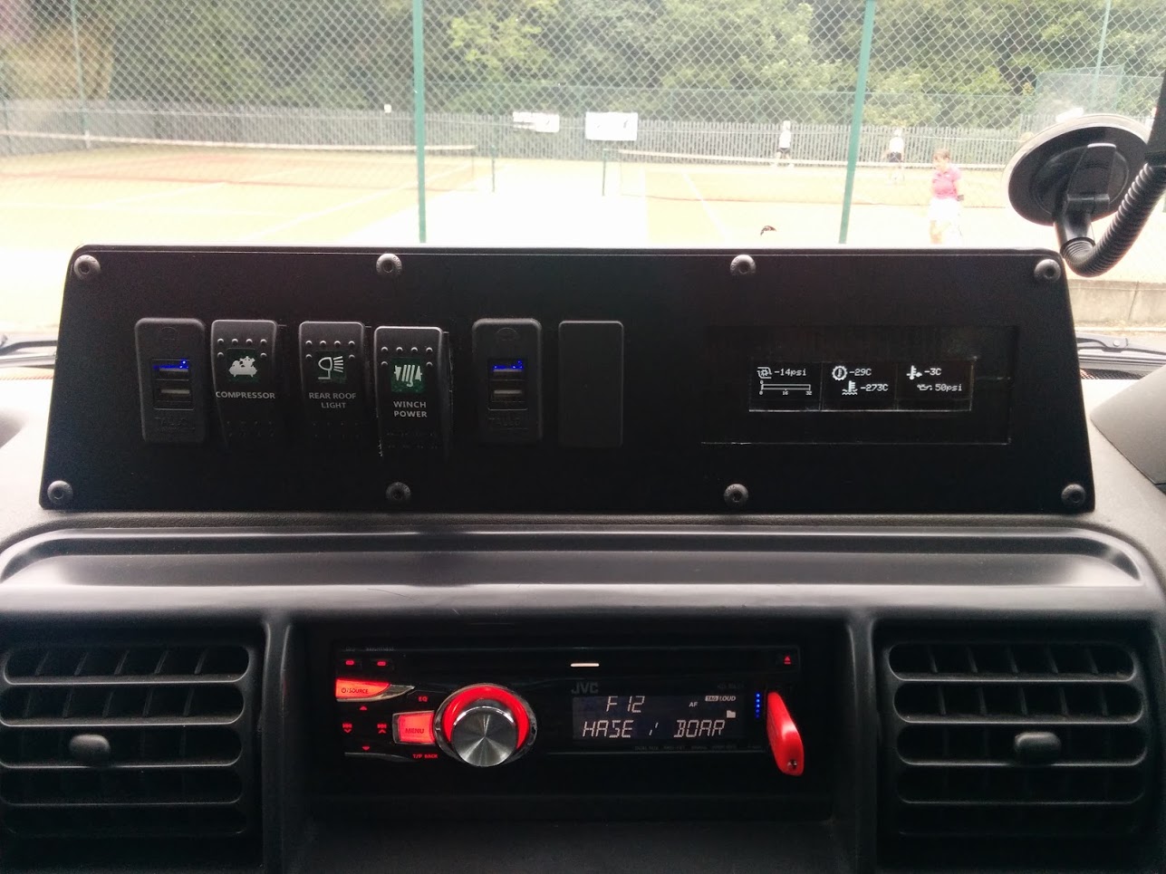
Nano system in the car (prior to sensors being wired in)
Data capture has proved pretty simple, most time has been spent on how to get the data to the user.
Video of the STM32 system with inclinometer
[youtube]https://www.youtube.com/watch?v=KDIy4PNw3LQ[/youtube]
Project github here -> https://github.com/BennehBoy/LRDuino
I used this repo as the base code since I like the gfx work done -> https://github.com/G6EJD/ESP8266_micro_ … C5883_OLED
Spent a lot of time refactoring my code, not directly related to this device, but to allow for multiple graph styles and pairing sensors together for display purposes.
Only to realise that these devices are probably garbage for the intended applications:
* they require the device to be parallel to the ground for the reading to not be influenced byt eh Z axis – not going to happen in a vehicle.
* they are strongly influenced by nearby ferrous material – kind of hard to get away from this in a vehicle.
I’ve seen sniffs of code out there where input from an accelerometer can be used to factor in Z axis changes – but I need to find some code, and this will also be affected by vehicle acceleration.
So, it looks pretty, and I got some overall system improvements from the refactor.

But.. best to avoid.
I’m not sure about the ferros metal issue, but I had to calibrate by rotating the device through 360 deg in all 3 axis multiple times, and making sure I had data for all quadrants.
I ended up using code called RT IMU, on github, but I think he stopped supporting Arduino some time ago, and moved to RPi,
https://github.com/RTIMULib/RTIMULib-Arduino
But if you are keen to investigate motion sensing and magnetometers etc, its probably one of the best code libraries, albeit quite complicated
Some useful info on using quaternions to correct for roll/pitch of the horizontal plane, bottom section of this -> https://github.com/RTIMULib/IMUStuff
The code does a lot of clever stuff ![]()
I used it for a while to try to do indoor navigation based on one of the 9 axis sensors, but found there was too much integration error to make it usable.
But I’m sure some of the features in the code could be useful if you had a 9 axis sensor, as you’d get tilt in 3D as well as compass etc, as well as acceleration and rotation speeds etc.
If you do offroad, it could be interesting to record things, and play them back later.
Yes, RTIMULib is no longer maintained on the Arduino.
I recommend using Sparkfun’s MPU9250 Arduino library from Github instead:
https://github.com/sparkfun/SparkFun_MP … no_Library
It is a derivative of Kris Winer’s library here:
https://github.com/kriswiner/MPU-9250
Very good information from its Wiki:
https://github.com/kriswiner/MPU-6050/wiki
… But it is itself a derivative from original Sebastian Madgwick’s algorithm:
http://x-io.co.uk/open-source-imu-and-ahrs-algorithms/
Please note that unlike Kris Winer’s implementation this one uses an optimized Fast inverse square root:
https://en.wikipedia.org/wiki/Fast_inverse_square_root
… But Sebastian Madgwick’s algorithm is itself based on Robert Mahony’s algorithm:
https://hal-univ-tlse3.archives-ouverte … 6/document
The main idea behind Mahony’s algorithm is to use complementary filters (high/low pass) on each sensor based on its capabilities and Madgwick’s idea brings in the fusion of sensor data together using a spherical gradient (think it as interpolation on a sphere), rather than the using full Extended Kalman filters used by RTIMULib, which are computationally more expensive:
http://www.unitedthc.com/DSP/Kalman1960.pdf
http://www.pages.drexel.edu/~hgk22/cour … cy1961.pdf
Here are also some good resources on magnetometer calibration using a 3D ellipsoid approximation, much better than standard xmin/xmax/ymin/umax methods used everywhere:
https://edwardmallon.wordpress.com/2015 … r-arduino/
http://sailboatinstruments.blogspot.fr/ … -part.html
https://sites.google.com/site/sailboatinstruments1/home
http://forum.arduino.cc/index.php?topic=265541.0
If you do offroad, it could be interesting to record things, and play them back later.
I’ve successfully paired it with my windows pc and done some testing with a 2560.
I’ve found an ELM327 emulator -> https://icculus.org/obdgpslogger/obdsim.html
But this is hardcoded to use a virtual serial port name which is created by this product -> https://sourceforge.net/projects/com0co … p_redirect
What I would like to be able to do is remap or reroute all io from the BT serial port of the HC05 (COM14 etc) to this virtual address.
I can then start to code on the STM32 using an ELM 327 library, the target physical OBD ELM327 device includes an HC06 slave. This means I don’t have to work against an actual vehicle whilst developing.
Anyone know of anything? I’ve had a bit of a scoot about on Google but everything like this seems to be a paid app.
I did obtain the source code but it’s quite a bit out of date so fails to compile – tried both cygwin and msys, all threw errors that I didn’t want to invest the time to attempt to debug.
I did speak with the author who was quite friendly but OSX based so unable to help much.
Anyhow….
Things move on.
I got the HC05 hooked into the project and can request pids via it using a generic OBD to Elm327 library. I’ll be testing this in car probably at the weekend. For now it’s just grabbing one PID, I need to work each of the most common calls into my sensor reading and data storage code.
This will most likely cover: RPM, Speed, Bat Volts, MAF, Ambient temp, Intake Temp, Engine Coolant Temp, Fuel, Throttle Position, anything else useful
So, although this will be relatively easy to glean from an ELM327/HC06 cheap Chinese OBDII type dongle, it will NOT work with the LR TD5 engine because it’s ECU predates OBDII and is only partially compliant with an early draft of ISO14230 / KWP2000. The TD5 also requires a key be generated from a supplied seed (LR security) – fortunately a keygen for this is on github (will put credits in my repo).
My solution is to build a translation dongle – basically it will probably include a small form factor 328P driving an HC06 via serial for the ELM327 emulation to be transmitted, then a softwareserial line interfaced with an L9637 K-line driver to talk to the TD5 ECU.
I’ll simply poll the most useful PID’s every 250ms (or maybe 500), lob the values in a struct, and read from this when ELM327 commands come in over the HC05 uart.
Bonus to this is I can also use the code to build an ELM327 bare bones simulator.
So, lots to do but it’s all fun fun fun.
Personally I stopped using devices like the HC05 and HM10 a while ago, in favour of using the nRF51822 BLE device, as you can program the nRF51822 using various Arduino repos, or with Nordic’s own SDK, ( using gcc). But again, that adds loads of extra work to the project
All it needs to be is small, so it can sit within an OBD type connector housing, it’s basically going to pretend to be an ELM327 knockoff OBDII dongle.
Here’s what is inside the dongle that I already have:

There’s a nice teardown albeit in German here -> http://www.brunwinkel.de/2014/05/zerleg … rs-elm327/
I was going to go with HC05/06 and arduino pro mini simply because I have some mini’s laying about.
In reality I probably won’t do anything other than the TD5 translator.
But… anyone with their own requirement can just fork the code.
The nice thing about the ELM is it covers a whole host of common OBD protocols and standards so it has a really wide footprint of coverage.
One of my friends who owns a Subaru is dropping very large hints ![]()
However I was thinking of buying an OBD device, as I had warning lights a few months ago, which had to be reset (I had to pay $60 for them to look at the car and do the reset, and that was a cheap price not at a Subaru dealer)
Coupled with any from a plethora of free phone apps you can clear just about any fault.
I’ve got a dedicated hardware device for my vehicle which cost about 300 quid – Nanocom Evolution.
I very strongly suspect that it’s a PIC or Arduino device coupled with external flash, colour touchscreen, and an SDcard. Fear of knackering it has so far prevented me from opening it up. It can talk to all of the multiple pre OBD ECU’s in the vehicle, and do a lot of nifty stuff. http://www.nanocom-diagnostics.com/
However I was thinking of buying an OBD device, as I had warning lights a few months ago, which had to be reset (I had to pay $60 for them to look at the car and do the reset, and that was a cheap price not at a Subaru dealer)
Be warned though you may fall asleep – although it gets juicier as it goes on, honest ![]()
TODO:
Software:
* Refactor compass & inclinometer to use the MPU9250
* Build in standard OBD PIDS & build code to query them using ELM327 library
* Write oil pressure sensor code & calibrate
* design and code a new input system where sensors can be re-ordered enabled/disabled, warning/max/min levels set.
Hardware
* refactor the breadboard to have 8 OLED’s (needs 2 more CS lines, I’ll be down to 4 unused pins)
* refactor inputs to have a left, right and select button (down to 2 free pins)
* Build psu for 5v devices (boost sensor, & pressure gauge)
* build 3.3v dividers for 5V device inputs into the ADC
* build stripboard for ‘control box’ side
* build stripboard for ‘head unit’
TD5 to ELM327 translation Dongle
* build hardware
* cobble together the various bits of code found online
So all in all, plenty to go at yet. I’m waiting on a bluetooth USB doohicky to come in the post so I can get the ELM327 emulator that I found tlaking to the outside world from within virtualbox, it won’t play with the onboard BT host for some reason.
I then attached a USB bluetooth dongle to the virtual machine.
Using this I paired with the HC05 on my project board, this adds 2x COM ports.
I outbound, and 1 inbound.
Using an ELM327 library I can transmit PID queries into the simulator via bluetooth.
But here’s the kicker, the comm ports are unidirectional… how can I get the results sent back over the inbound COM port???
Is there some way to bind the 2 ports together into a singlw virtual port in windows?
So further debugging required.
This means the ELM327 library is probably utter gash.
And I nee to stop writing HC06 when I mean HC05 ![]()
I had used HC-05 previously for getting some debug logs from STM32 in wireless manner. However I’ve found that sometimes a bit cumbersome as windows may not connect to the virtual serial port for HC05 always. So I’ve thought to switch to ESP8266 so that it connects to STM32 RX/TX and provides a TCP socket server for debug logs..
I had used HC-05 previously for getting some debug logs from STM32 in wireless manner. However I’ve found that sometimes a bit cumbersome as windows may not connect to the virtual serial port for HC05 always. So I’ve thought to switch to ESP8266 so that it connects to STM32 RX/TX and provides a TCP socket server for debug logs..
String inString="";Anyhow I’ve managed to obtain some success by switching back to the previous library I was using and then doing some filtering of the data coming into the serial port – effectively I’m stripping anything which is non alpha, a space, or the ELM327 prompt character.
The input parsing is much stronger in this version of the library but it couldn’t deal with lots of cr lf’s , which the simulator is throwing out left right and centre with it running on Windows.
Result.
The dodgy inString code below is just to send debug info to the serial port, it shall be gone shortly!
byte Elm327::runCommand(const char *cmd, char *data, unsigned int dataLength)

{

byte cmdLength;
// Flush any leftover data from the last command.
// Send the specified command to the controller.
flush();
ELM_PORT.print(cmd);
ELM_PORT.print('\r');
unsigned long timeOut;
int counter;
bool found;
byte temp;
String inString;
// Start reading the data right away and don't stop
// until either the requested number of bytes has
// been read or the timeout is reached, or the >
// has been returned.
//
counter=0;
timeOut=millis()+ELM_TIMEOUT;
found=false;
while (!found && counter<( dataLength ) && millis()<timeOut)
{
if ( ELM_PORT.available() ){
temp = ELM_PORT.read();
if ((temp >= 48 && temp <=57) || (temp >= 97 && temp <=122) || (temp >= 65 && temp <=90) || (temp == 62) || (temp == 32)) {
data[counter]=temp;
inString=inString+char(temp);
if ( data[counter] == '>' ){
found=true;
data[counter]='\0';
}else{
++counter;
}
}
}
}
Serial.println(inString);
// If there is still data pending to be read, raise OVERFLOW error.
if (!found && counter>=dataLength)
{
// Send a character, this should cancel any operation on the elm device
// so that it doesnt spuriously inject a response during the next
// command
ELM_PORT.print("XXXXXXXXX\r\r\r");
delay(300);
return ELM_BUFFER_OVERFLOW;
}
// If not found, and there is still buffer space, then raise no response error.
if (!found && counter<dataLength){
// Send a character, this should cancel any operation on the elm device
// so that it doesnt spuriously inject a response during the next
// command
ELM_PORT.print("XXXXXXXXX\r\r\r");
delay(300);
return ELM_NO_RESPONSE;
}
char *match;
match=strstr(data,"UNABLE TO CONNECT");
if (match != NULL){
return ELM_UNABLE_TO_CONNECT;
}
match=strstr(data,"NO DATA");
if (match != NULL){
return ELM_NO_DATA;
}
if (strncmp(data,"SEARCHING...",12)==0)
{
// Remove searching...
byte i=12;
while (data[i]!='\0'){
data[i-12]=data[i];
i++;
}
data[i]='\0';
}
// Otherwise return success.
return ELM_SUCCESS;
}
Top left two displays are being fed via Serial3, connected to an HC05 which is paired with a USB dongle which is running on Windows XP inside a virtual machine running atop Windows 10 which is running an OBD simulator which runs on top of cygwin. Which is all running within The Matrix…
![]()
![]()
![]()
Always one for the simple stuff!

It seems that the ELM simulator (or some other part of the UART chain) is randomly deciding to echo anything arriving on RX to TX…
Any ideas folks?
I can add some frig code in that checks to see if any characters sent are echoed back and remove them from the buffer but it’s a bit of a blinking pain in the bum!
Wasn’t leaving enough time for the BT connection to come up before tte library tries to disable echo from the 327.
Doh!
Built a voltage divider using a 10K & 5.1K resistor which gives ~3.3V as max input to the ADC.
Sensor puts out 0.5v at 0psi, 2.5v at 50psi, & 4.5v @ 100 psi.
That equates to 0.33v, 1.65v & 2.97v respectively once the divider is in play.
To get to a pressure value in the STM32 we do this:
sensor slope = MaxV – MinV / MaxP – MinP
= 2970 – 330mV / 6894 – 0millBar
= 2640 / 6894
= 0.383 mV per milliBar
We know that the ADC divides the voltage into 4096 slices so we can find mV per ADC code
= 3300/4096
= 0.8056 mV per ADC code.
We can roll the two factors together to find a single milliBar per ADC code factor
0.8056/0.383 = 2.1034 millibar per ADC code.
So the ADC raw value * 2.1034 / 10 then converts to Kpa
We multiply this by 0.145038 to get psi, and then subtract 14.5 to account for atmospheric pressure (at sea level).
Although in reality the sensors have a bit of bias from atmospheric so we need to tune the subtraction amount.
The exact same applies for boost/MAP sensors although the sensor slope differs.
I normally write all the equations into the code, in full, and then if necessary optimise them later (but keep the original, long version as a comment)
You probably already know this, but …
If you are dividing and multiplying, its often best to look at the order in which the compiler will do the maths, especially as division is often done first, as doing division first can lead to loss of precision, especially when working with integer values.
And integer maths is a lot faster than floating point. So if I only need 2 or 3 decimal points of accuracy, I multiply the original input by 100 or 1000, and use integer maths (as long as the value will fit in an integer), then split out the integer and decimal point parts when I display the value.
But obviously it depends on what you are measureing. e.g. I have some thermometers which are accurate to 0.5 deg C, so I just double the value and use an integer, rather than wasting time with floating point processing of what isn’t a very accurate measurement in the first place.
Regarding integer calculation, I’ve tried converting some of the float stuff and always end up making a hash of it, must try harder ![]()
One thing it’s doing, is sending out a command, then spining in a loop until it gets a response.
This is burning ~ 100ms of dead time whilst the simulator replies to each command.
I’d prefer to transfer control back to my main loop’s state machine, and then use serial.event to process responses.
Could anyone suggest any appropriate reading or sample code for this?
Because the OBD reading is so slow and I need to be able to process ~10 PIDS (maximum) I’m going to stagger the OBD reads in the state machine, PIDs which need a high frequency response will be read multiple times per second, but slower changing data will be read less frequently. I’ll probably do this for the analogue data too…
And integer maths is a lot faster than floating point. So if I only need 2 or 3 decimal points of accuracy, I multiply the original input by 100 or 1000, and use integer maths (as long as the value will fit in an integer), then split out the integer and decimal point parts when I display the value.
You could always post your equations here, and see if anyone has any ideas
When I get above a few OBD requests per 250ms the simulator (and I assume real ECU’s) begin to queue the commands internally and the responses come back asynchronously.
I think I need to issue commands based upon the speed that the data is likely to change, eg RPM I’d probably want to update every 250m/s but coolant temp could be a few seconds or longer interval.
I’ll update my state machine to have a few different levels of data frequency requirements and then pop the requests in a queue.
I need to be able to issue the commands either batched up or on a regular interval, so it seems the best way to achieve this is to have a couple of FIFO’s
Naturally I need to make sure the queue doesn’t get overun.
One for outbound commands.
Another to store responses – this would be populated using a serial event. main code loop would then iterate over all the responses in the queue and process them.
The data sheet for the 327 states that it will only perform synchronous processing, anything sent to it whilst it is processing the current command is ignored unless it contains a carriage return – in this scenario is aborts the current process.
I still want to decouple the response processing from the command calls – currently the command calls spin in a while loop until a response comes back. This can take anything up to 200ms. Clearly this is a waste of cpu cycles. So with this in mind a FIFO for the responses may be of use.
What I need to figure out is whether the core serial buffer will hold enough response from the ELM for me to go on to doing other work and only processing the serial responses via serial.event which I believe happens every main program loop. I guess that serial handling is interrupt driven so this ought to work (I’ve not checked the core source yet to ascertain the default buffer size).
I think given use of a buffer in my serial.event code, and reading in all characters, I should be able to check if the ELM command prompt has been issued.
Assuming it has a simple case statement can be used to check the response type and populate my array of sensors with the appropriate results. I can also set a flag ‘ELM_AVAILABLE’ or similar which can be used to prevent further commands being issued in my loop if it is false.
All of this will probably rely quite heavily on the main loop being optimised.
I’m also making an “onboard car computer” initially using ELM327.
Quickly found that ELM327 clones don’t support all the AT commands (i.e. ATIB XX will be equal to ATI) so ditched that option.
My car is an Audi A4 and it uses the K-Line protocol. I’ve found an example code online (KW1281) and I’m modifying it to work on my ECU.
It’s still WIP but I’m making progresses.
What protocol does you car use? Maybe ditching the ELM327 can be an option if you have so many problems…
I also got times where BT connection would go down and had to reboot the ELM and the HC05 too…
I’m working on porting some code that talks using this protocol and have got it to work with an ecu emulator. I’ll be fabbing up the actual K-line circuitry this weekend using an L9637D line driver, but I need to get my hands on a plug for the OBD port (I may butcher an ELM 327 that I have).
It may be that this port (which is partially functional now) would be a good start point for you -> https://github.com/BennehBoy/td5opencomstm32
The only finicky bits that will likely differ is that my vehicle expects a key response to a seed, you might need to hack that bit out of the code. It also has some strict timing to start the initialisation (300ms K-line held active), and 25ms delays between responses.
The emulator is also in the archive so that too might be a good place to look.
If you have a logic analyser I’d strongly recommend that you sniff the k-line on your vehicle, probably best done in conjunction with a working diags unit (which sort of defeats the purpose!).
Happy to help with any queries you might have.
To be clear….
I have working ELM327 code that happily reads generic diag info from an ELM327 emulator. My ELM clone also does not support k-line so it fails to work with this, however it will read the same PIDS from CAN vehicles.
I _also_ am working on a K-line based port of a diag system that is for my actual vehicle, the intention is that I will either directly integrate the code into my other project, or more likely I’ll make an ELM327 translator that my other project will connect to via bluetooth.
– stripped the OBD USB adapter and connected wires to RX, TX and GND.
– plugged the logic analyser and made some reading.
– Captured the waveforms, decoded it all with the software and exported to CVS file
I got the 5-baud init to work and got the ACK ok but now the code doesn’t recognize the stream that the ECU sends with the name string.
Have to debug that.
I stripped one of my ELM dongles to connect it to the K-line but I also have some MC33660 that I am still experimenting on.
What does the td5 mean? Will the code work on ISO9141?
I doubt the code will work with 9141, I suspect all the command/PID id’s will be different. Although, isn’t 9141 just the K-line transport layer? With 14230 being the protocol layer sitting atop it?
https://en.wikipedia.org/wiki/On-board_diagnostics
They seem to refer to the lower layers of the OSI model (maybe physical and link layers).
From the Wiki the ISO 14230 is “Physical layer identical to ISO 9141-2”.
KW-1281 and KWP2000 specify the application layer. So maybe the diference is only there…
I recommend using Sparkfun’s MPU9250 Arduino library from Github instead:
https://github.com/sparkfun/SparkFun_MP … no_Library
https://en.wikipedia.org/wiki/On-board_diagnostics
They seem to refer to the lower layers of the OSI model (maybe physical and link layers).
From the Wiki the ISO 14230 is “Physical layer identical to ISO 9141-2”.
KW-1281 and KWP2000 specify the application layer. So maybe the diference is only there…
I’ve forked it, fixed it, and submitted a PR. Simple fix, they send the wrong WHO AM I code…
Fixed version here -> https://github.com/BennehBoy/SparkFun_M … no_Library
Still getting spurious results, need to get some stiff copper wire to make up a header to pin it to some stripboard.
They do the same thing on the BME280 etc.
They configure the hardware onto its alternative address, using a pullup or pulldown on the device, and their code only works with the alternative address.
I think this is deliberate to make it hard for people to use their libs on modules from China.
They do the same thing on the BME280 etc.
They configure the hardware onto its alternative address, using a pullup or pulldown on the device, and their code only works with the alternative address.
I think this is deliberate to make it hard for people to use their libs on modules from China.
I see no reason for Adafruit to have their BME280 on its alternative address apart from so their code library isnt immediatly usable for anyone elses modules.
I see no reason for Adafruit to have their BME280 on its alternative address apart from so their code library isnt immediatly usable for anyone elses modules.
Sorry, as this sounded just the same as the things Adafruit seem to do, I didnt really read the whole post and didnt spot that it was Sparkfun
Sorry, as this sounded just the same as the things Adafruit seem to do, I didnt really read the whole post and didnt spot that it was Sparkfun
There must be a way for me to multiplex those CS lines onto 4 pins only by writing out binary combinations and using some logic to set the appropriate lines high?
Can anyone recommend something?
But as I expect that the Enable is active low, It may not be possible.
(BTW, even on the 74HC42, there is no EN line, it is BCD directly)
(BTW, even on the 74HC42, there is no EN line, it is BCD directly)
pcf8574’s are an 8 bit i/o port, that would allow you to make 4 off bit bang i2c, use 2 for 8
not sure which you require?
i suspect driving 4 sets of i2c ie software required; might be interesting ![]()
stephen
So, using a I2C gpio expander is maybe too overkill, and it takes more time to settle the pin since it is I2C.
Simple demux will settle pins as soon as the gpios driving it are set.
then he could also relatively easily test if the manufacturers caution is warranted as well ?
stephen
This is helped because I have an array ‘Sensor’ structure where all of my sensor definitions are stored.
So a simple toggle item for on/off for a sensor becomes:
TOGGLE(Sensors[0].senseactive,sensor0Toggle, "Boost: ",getSensecount,enterEvent,wrapStyle//,doExit,enterEvent,noStyle

,VALUE("On",true,doNothing,noEvent)

,VALUE("Off",false,doNothing,noEvent)

);
As mentioned earlier however I’m struggling for GPIO pins…
Can Boot0 (PB8) be used as GPIO? I’ve just tried and my SD card initialisation fails…
If not I can test using an alternate pin.
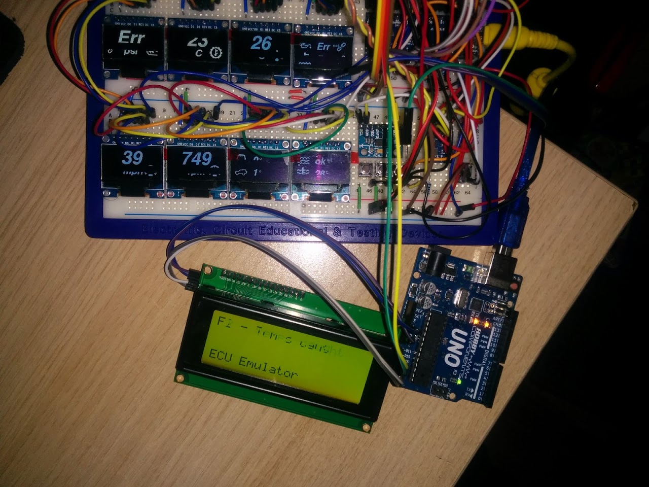
Photo of the TD5 ECU emulator running on an Arduino Uno, PID types being requested get displayed on the LCD.
At present the gauge system is directly querying the Arduino via serial @ 10400 baud (ISO14230-1 standard speed), but it should work equally well via the L9637D K-line drivers I have directly to an ECU.
Getting awfully close to end dev now.
A friend is loaning me a spare ECU so I can do a lot more bench testing.
But the picture in the last post isnt visible
BTW.
Did yiu start your PCB design yet ?
I really should.
I’ve got all manner of other projects in mind.
I’ve also managed to get my KW1281 code to work properly! ![]()
I can now get fuel consumption data! But I’m going to use a ILI9341 on my setup. It’s hasn’t got ideal visualization properties but it’s cheap and nice color and resolution for the purpose ![]() OLED would have been perfect for auto environment but… maybe latter lol
OLED would have been perfect for auto environment but… maybe latter lol
I’ve not yet stuck the latest code on github, I may fork it off so that the ELM version and this can coincide.
I’m also going to split the Ecu emulator out into it’s own repo as I’ll be adding much more PID recognition into that and the ability to adjust outbound info using a menu system.
I’m now considering building a transmission control module for the ZF4HP24 automatic gearbox used in these land rovers – the factory controllers have less than optimal transition points and TC lockup… but that will be a whole other level of difficulty.
ECU Emulator split into it’s own repo -> https://github.com/BennehBoy/TD5EcuEmulator
@Rexnanet, it would be interesting to see your PID payloads and expected responses, I can perhaps look to code them into the ECU emulator then?
Another plus side of using the demux chip is that I can mount it on the display daughter board which means less wires to be run to it (it’s ~ 75cm away from the controller).
I’m now also thinking about how to mux my button inputs up – I have 5 buttons but would possibly add a sixth if I can multiplex them, it doesn’t matter if they block one another.
Obviously complexity levels go up but it’s only marginally.
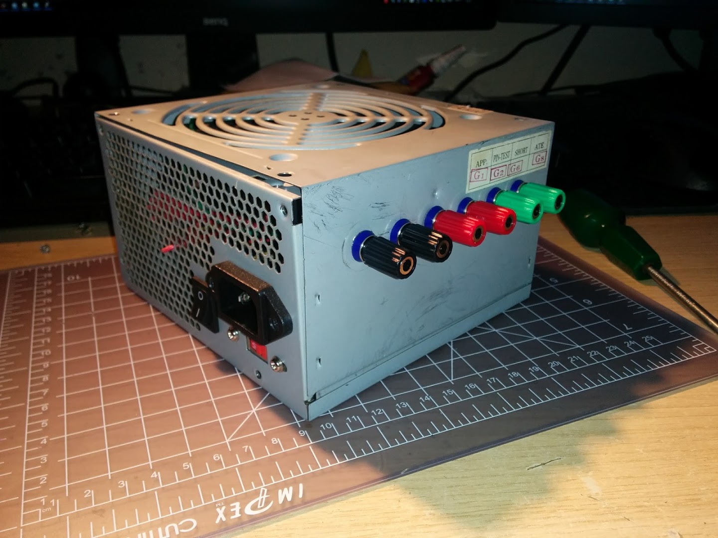
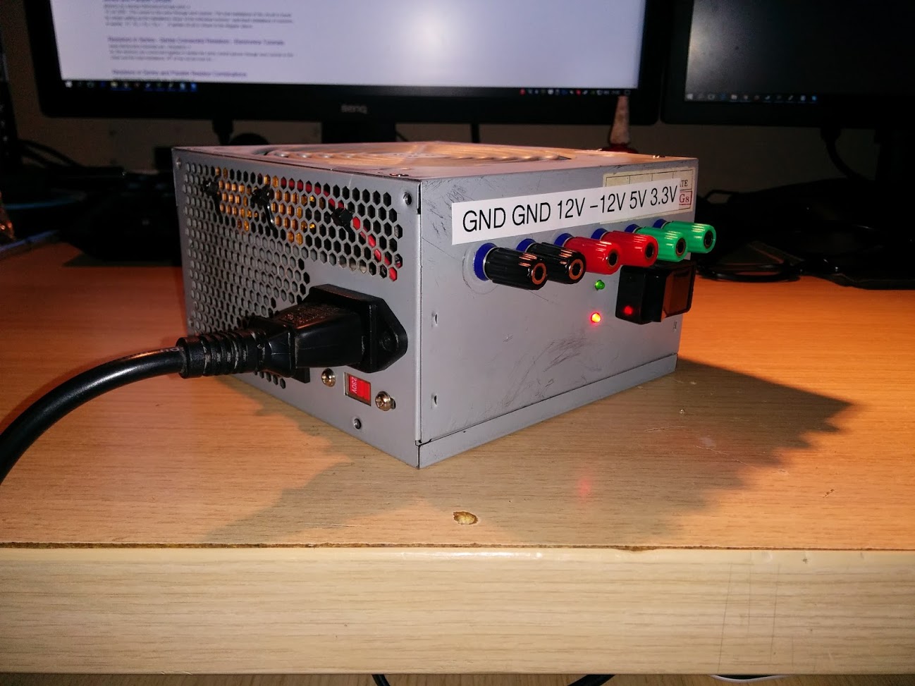
I’ll need to simulate an ignition switched relay turning on the main power which should be fairly straightforward, but I don’t have a bench PSU…
So, I started converting a spare 650W ATX PSU into a bench supply, it’s pretty straightforward, the only thing to keep in mind is that the highest rated output needs a dummy load in order for the voltages to be stable. In the case of this PSU it’s rated like this:
+12V1 – 23A
+12V2 – 23A
+5V – 40A
+3.3V – 30A
-12V 0.8A
+5V/SB 3.0A
I’ve got a couple of 10W power resistors coming in the post that I’ll load onto the 5V line (although I’ll probably hook both 12V outputs into one rail so that will techincally be higher output).
might be nicer than toggling the mains switch to the psu
stephen
might be nicer than toggling the mains switch to the psu
stephen
BTW. i have one of those cheap’ish, 0 – 30V 1A variable PSUs, which also has a variable current limit; and I find it very uswful.
However sometimes 1A isnt enough, as the current regulator can kick in durimg initial surges, so i think I will need to build something like that PSU for when I need more current in either 5 or 12V
I did read somewhere that the 12V needed load for the 5V to work,or perhaps it was the other way around.
But that may no longer be true.
A scant few lines of code changes to the adafruit_ssd1306 library and it’s now working.
There’s no method within the library to clear all the outputs so for now I’m just writing an out of range line active to clear the CS lines on my screens. When I get a moment I’ll fork the library on github and add a clear method that simply sets E1 thus disabling all the outputs.
So that’s freed up 3 GPIO’s, which means I now have working SD & a luxurious 2x unused GPIO.
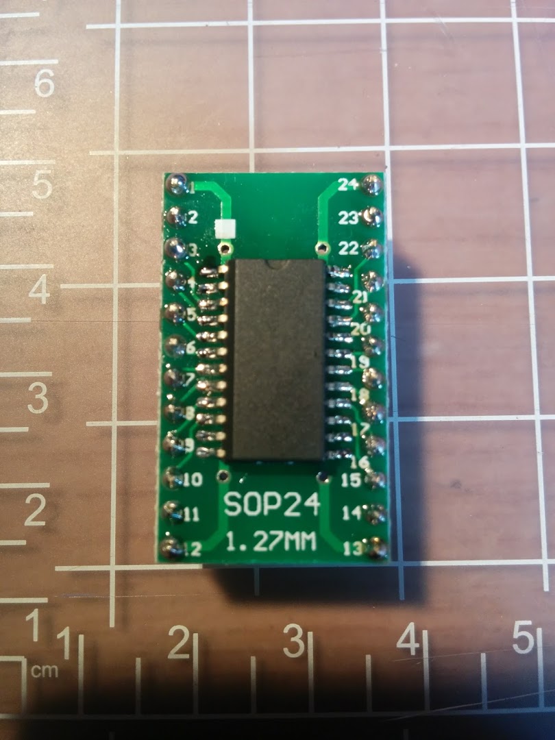
The reason I ask is that if my MAX31856 is in circuit (which is just soldered to a TSSOP to DIP adapter), then SD fails to work.
Remove the MAX and all is well – could it be that I’ve neglected to do something obvious with my implementation? resistances to ground etc at the device end?
using the same /cs line ? yeah i know
does the MAX31856 work if SD is removed ?
stephen
All the OLED screens were hooked up along one spur of the bus, then there was a run of cable from the SPI pins out to the MAX, and then another run out to the SD card.
I’ve now hung the MAX off the end of the cable run to the SD card and it’s working fine. Move it back and it fails.
Live and learn.
srp
srp
i either get a hang with the Wire examples or every address is a device
stephen
I’ve got 2 devices on the same bus, an ADXL345, & an HMC5883.
Luckily I’ve got 3.
ok now i follow, max31856 modules are 2.5x the chip price
favour please, see if the i2c scanner examples work?
if so,
which board and/or variant?
what arduino version,
date of arduino_stm32
which platform etc etc
stephen
I’ve not cloned the stm32 repo for about 4 weeks though…
1.81 IDE
Board is a Maple Mini clone, it looks exactly like a Baite but doesn’t have the logo on the silkscreen
Scanning...

I2C device found at address 0x1E  !

I2C device found at address 0x53  !

done
my magic is working again, remember 4000 series cmos, look at it askance across the room and it died.
i honestly believe i am much the same with usb bus, i2c bus & stm32
mind you i got Enrf24 returning correct status, actually one of the 103rc with built-in nrf24 socket, so not all bad.(on the wiki)
looks like a clean install is required. again and again.
totally off the cuff, one of the vendors for a stm32f407 boards is adding a panel ‘click here to add suitable display’ to order
https://www.aliexpress.com/item/High-Qu … 0.0.uxJMgT
display is extravagantly priced, but then again no hunting for suitable one. i think the board is not so bad
https://www.aliexpress.com/item/Color-t … 0.0.uxJMgT
stephen
to something including the version ./.arduino-182. i’m now running 1.8.1 compiled from their archive source code and ./.arduino-1.8.1r0 as config dir. and Due installed etc, etc
scanner-wire seems to have unknown error for all device addresses, scanner-hwire has a device at all addresses.
saying that if i use todbot(?? original author) scanner, that works fine on avr
i’ll try again with a virgin blue pill when i find the soldering iron. first i’ll try with uno and or a nano
stephen
when i was working and using a motor bike or pedal recumbent trike to work, it was every day about 0645 ![]()
Inspired Cycle Engineering Trice QNT, Falmouth, now with a mesh seat and an Argos trailer, 5 months from Blackpool to Blackpool via Lands End and Dover, staying within 5km of the sea. About 2500mls.
6 wks of stops, various 3-5days’ish (not in sequence) for Liverpool, Wirral, Bangor, Abersytwif, Shell Island, Barmouth, St Davids, Tebay, Cardiff, Hunters Inn, Falmouth, Exeter, Eden Project, Poole, Brighton, Portsmouth, Dover, Southend on Sea, Skegness, Hull, Preston and many one nights in between.
Hunters Inn is in a valley, easiest gradient out is 1 in 7, on a Sunday, going in i had 1 in 6, 1 in 4, 1 in 6 and a 90 degree left bend.
i investigated the tangent crunching at 18.6mph (£1200 to repair), back on road Weds 6pm.
they(ICE) came from Falmouth with a hefty set of spares, workbench and tools in an estate car.
when i got back, my doctor honestly did a triple take when he saw me, rather tanned and about 4.5 stone lighter, sadly mini-stollens re-entered my life.
somewhere i have a lot of photos, some mp4 and the gps track, few gig
highlight, decent drizzle, 5mls of slow, slow climb (alt route to a really nasty 1 in 4) picking
miniature strawberries. i can still taste them 5yrs on
stephen
I few people around here ride recumbents, but I’ve not seen one with a faring.
But mini stollens…. mmmm.
Looks like there are loads of differnt types available.
I will probably buy one of the larger ones. Not sure whether to get USB or Bluetooth, but I would rather have one I can take apart, and separate the Bluetooth or USB comms from the OBD interface
And yes, it has odb… 1. Kinda, with special connecto, of course (round). Germans….
I just looked, and it has something plugged into the OBD port with a wire between 2 of the pins.
But I’ve no idea what that’s for.
I just looked, and it has something plugged into the OBD port with a wire between 2 of the pins.
But I’ve no idea what that’s for.
I wil take a phpto when I get a free 10 mins;-)
No magic smoke! ![]()
![]()
1x Head gasket failure – successfully fixed last weekend.
1x Gearbox failure – repair in progress
Since all bad things tend to come in threes I’m hoping the third one will be minor.
srp
<edit>
add ‘on restart’ , gasket followed by gearbox, does it suggest a transmission problem causing overloads ?</edit>
That doesnt sound like much fun.
But it’s allowed me to do some hardware hacking… I’m uprating some of the bearings int he gearbox to make it stronger. The actual fault I’m fixing has nothing at all to do with that though, a 5 quid part broke and fell to the bottom of the gearbox which meant the whole thing had to come off….

[Pito – Thu Jul 06, 2017 12:32 pm] –
Edd China may help you with it
He needs a new job ![]()
Still not unpacked.
Got a bit distracted by an upgrade to my pc system : Ryzen 1700X with an NVMe SSD – man that thing flies!
I’ve come across a number of the same issues you have been having, and because of eternal scope creep (don’t we all know about that), I’ve found some decent solutions to it all…
I too was getting to the point where my rats nest of wiring was starting to cause all sorts of electrical interference, etc, as well as 3.3V/5V compatibility issues, Processor load problems, and so on…
So what I did was make a few small boxes to collect data under the hood.. they all talk over CAN to each other, which eliminates ground problems, etc… Also, I have one box with an Arduino Pro Mini that takes care of all the 5V sensors, no need for resistor bridges. Then I have a blue pill that takes care of all the 3.3V stuff.. 9DOF, BME280, MAX31856’s… Inside the cab (a work in progress), another blue pill that has a rotary encoder input (for data selection) and takes care of the display(s), blinky LED’s, and so forth. I also have an HE351VE turbo which is a variable vane turbo that is controlled via CAN bus, so as a remnant of previous efforts, it is still controlled by a Mega2560.. That will change in the future.
Another node will be added at some point when I get a different injector pump that will be electrically controlled (PWM signal).
I’m supplying each node with it’s own 12V power and CAN signal lines.. so pretty much it’s just 4 wires to each one, makes for much neater wiring and no more ground loops… Also, it’s a little easier to code for, at least for me.
If you’re using a 100PSI generic pressure sensor for a lot of things that don’t go over ~65PSI, you don’t need to have any resistor bridges… The other option is to go a step up in sensor range.. Just an idea!
Lastly, since I hate loss of precision when I can help it, I do a lot of work in floating point, and to transfer them from one node to another, you use a “union”.. it works wonderfully, low overhead, etc.
union Fourbyte{

byte b[4];

float f;

uint32_t uint32;

int32_t int32;

}
Fourbyte value1, value2;
void somefunction(){
value1.f = 1.2345f;
value2.int32 = -12345;
for(int i=0; i<4; i++){
Serial.println(value1.b[i], HEX); //display the value as it's stored in memory
}
}
maybe a different approach:
1) each display unit consists of a small mcu driving a display;
2) the display units act as slaves taken data input from a master and visualize it on the display;
3) a master collects take from obd2 and user inputs and sends the data to the display units where the visualization is handled locally.
This approach allows scalability and modulization: the display units should be highly similar to each other, and the communication will be quite simple to handle, potentially via uart or i2c, or whatever suits your environment.
So the master can simply tell a slave to render a particular graph, with titles, and range, and refresh periodically with a data item to be visualized.
As the slaves are identical, users can customize variables to be displayed on command.
It greatly simplifies programming and production: one piece of master and one piece of slave code running on multiple display units.
[dannyf – Tue Nov 14, 2017 9:57 pm] –
To just expand on my post above, each slave would be identical, with a library of charts or graphs, customizable by the master, to display a value sent by the master.So the master can simply tell a slave to render a particular graph, with titles, and range, and refresh periodically with a data item to be visualized.
As the slaves are identical, users can customize variables to be displayed on command.
It greatly simplifies programming and production: one piece of master and one piece of slave code running on multiple display units.
I really rather like this idea, parts are cheap enough but I’m probably too lazy to do all the fab and programming ![]()
[Rx7man – Sun Nov 12, 2017 8:23 pm] –
Interesting project…. I have similar goals on my ’94 Dodge (Cummins) diesel.. non OBD2 compliant vehicle.I’ve come across a number of the same issues you have been having, and because of eternal scope creep (don’t we all know about that), I’ve found some decent solutions to it all…
I too was getting to the point where my rats nest of wiring was starting to cause all sorts of electrical interference, etc, as well as 3.3V/5V compatibility issues, Processor load problems, and so on…
So what I did was make a few small boxes to collect data under the hood.. they all talk over CAN to each other, which eliminates ground problems, etc… Also, I have one box with an Arduino Pro Mini that takes care of all the 5V sensors, no need for resistor bridges. Then I have a blue pill that takes care of all the 3.3V stuff.. 9DOF, BME280, MAX31856’s… Inside the cab (a work in progress), another blue pill that has a rotary encoder input (for data selection) and takes care of the display(s), blinky LED’s, and so forth. I also have an HE351VE turbo which is a variable vane turbo that is controlled via CAN bus, so as a remnant of previous efforts, it is still controlled by a Mega2560.. That will change in the future.
Another node will be added at some point when I get a different injector pump that will be electrically controlled (PWM signal).
I’m supplying each node with it’s own 12V power and CAN signal lines.. so pretty much it’s just 4 wires to each one, makes for much neater wiring and no more ground loops… Also, it’s a little easier to code for, at least for me.If you’re using a 100PSI generic pressure sensor for a lot of things that don’t go over ~65PSI, you don’t need to have any resistor bridges… The other option is to go a step up in sensor range.. Just an idea!
Lastly, since I hate loss of precision when I can help it, I do a lot of work in floating point, and to transfer them from one node to another, you use a “union”.. it works wonderfully, low overhead, etc.
union Fourbyte{

byte b[4];

float f;

uint32_t uint32;

int32_t int32;

}
Fourbyte value1, value2;
void somefunction(){
value1.f = 1.2345f;
value2.int32 = -12345;for(int i=0; i<4; i++){
Serial.println(value1.b[i], HEX); //display the value as it's stored in memory
}}
I’ll be ditching the 9 axis code because the magnetometer is too easily swayed by ferrous objects nearby.
I’ll probably also park/hive off the ECU code to a separate project.
Anyhow, I have taken the opportunity to upgrade some of the libraries to newer versions and have corrected the code accordingly.
I then grabbed the latest git snapshot of Roger’s core and there are some problems….
1) any i2c inits hang the maple mini – if I remove the i2c code then the code runs.
2) only 4 of my SPI screens now work… I’ll need to investigate this one further though. can’t reproduce this, must’ve been a typo somewhere.
The core repo I wrote it all against is from last April.
[BennehBoy – Sat Jan 13, 2018 2:21 pm] –
<…>
1) any i2c inits hang the maple mini – if I remove the i2c code then the code runs.2) only 4 of my SPI screens now work… I’ll need to investigate this one further though. can’t reproduce this, must’ve been a typo somewhere.
The core repo I wrote it all against is from last April.
https://github.com/rogerclarkmelbourne/ … e07fb05+35
Use github to find a “before date” and use the right-hand symbol “<>” to cause github to provide a snapshot of that date. Try that ZIP. If it works, take the currentvZIP, expand into a temp directory and run a file compare program to identify what happened.
Good luck. I just keep my own Zip of my PC /hardware directory before I upgrade the core. There were lots of pull requests applied last year – lots!
Ray
I’ve dug out some threads which indicate some Wire changes – I’ll do some reading but for now it’s not a priority since the device I was using over i2c won’t be in the final project.
SDfat seems to have also transformed considerably. Again I kept a copy. This I do want to get working. Looks like the stuff for spi transactions has gone or been transformed somehow.
[BennehBoy – Sat Jan 13, 2018 3:08 pm] –
Fortunately I kept a copy of the repo that I originally built against, I’m a paranoid sort of soul
<…>
Yes. With changes coming in from numerous places, paranoid is a good state of mind. I’m git proficient `nuff but I still prefer ZIP archives on my own Linux server!
… paranoid is also why I take the time to incorporate library files into my sketch folder… libraries are not immune either. As I publish some projects, a single ZIP known to work with a specific version of the ArduinoIDE essentially minimizes my support on hackster.io.
I updated Chromium on my Linux systems a few days ago. Then the next day there was a Chromium update and then the next. If Google cannot get their QA and regression testing correct … well, what chance do we have with our github sources?
Be wise – backup everything.
Ray
however there may be a problem with multiple different I2C device libraries, which is probably something to do with the bus not being released.
Unfortunately I have not had time to test this potential problem
The difference is that this setup does not use 8 OLED screens and is not driving their CS lines via a demultiplexer.
So, I either have a logic error in my MUX154 code which is leaving an OLED CS line high, or there’s a wiring issue (I’m going with the latter because the jumper wiring to all the devices is a bit of a rats nest).
Am now going to stop futzing with scope creep, and concentrate on completing/polishing the datalogging and menu system prior to a vehicle install.
Should all just be functional code now that the hardware is sorted.
Made it compliant with latest core versions (as of 12/12/2018), Arduino 1.8.8, latest library incarnations, and also so that it will compile & build seamlessly on Maple Mini using Roger’s core or Black 407VET6 on STM’s core.
See here -> https://github.com/BennehBoy/LRDuinoTD5
I also refactored the ECU Emulator away from Arduino Uno, SoftwareSerialEx, & I2C LCD’s and onto Maple Mini & SSD1306 SPI OLED.
See here -> https://github.com/BennehBoy/TD5EcuEmulatorMM
Both are functional but could do with some polishing.
This is my first time ever using KiCad (or any schematic software) in anger so I’ve probably made a lot of schoolboy errors.
If anyone would be so kind as to cast an eye over it, suggest any glaring issues, conventions broken, protection circuitry that I should probably add then I’d be exceptionally grateful.
https://github.com/BennehBoy/LRDuinoTD5 … inoTD5.sch
Thanks.
PS power will be supplied from the vehicle battery supply so will hover between 12.5V and 14V, I’m using an MP2307DN based DC to DC Buck converter to step this down to 5v.
PPS L9637D circuit yet to be finalised (for K_IN, K_OUT)
I would take a look for you, but I do not use kcad myself. Can you pdf it?
So I’m now updating to V 5.0 and I’ll let you know what happens.
[misfet – Thu Jan 31, 2019 9:54 pm] –
Hi,
I would take a look for you, but I do not use kcad myself. Can you pdf it?
It’s Open Source…
Why not just download it: you may find it useful, even if just for a few hours to familiarize yourself then uninstall.
http://kicad-pcb.org/download/windows/
Ray
The only thing I’d note is that the schematic has symbols for various sensors, e.g. tacho, but I don’t think those sensors are on the board. I think perhaps some of the symbols for sensors may just be connectors to connect to external sensors.
(But I could be wrong)
Why not just download it: you may find it useful, even if just for a few hours to familiarize yourself then uninstall.
Ahh Ray, if only it was that simple….. In Australia we have a network provided by the NBN. It stands for No Network. With a B in the middle. I don’t think anyone knows what that is for. Anyhow, the NBN’s purpose was to trick the Australians into voting for an idiot for their president. And it worked. It also made a small handful of people a shitload of money.
What it is not so good at is providing an inanet connection. So downloading something the size of a program is no small ask.
Anyway, it has been grinding away on that all day now, so I will see how I go. But a pdf sure would be easier….
Doubt I’ll use it, I have arrived at a comfortable level with diptrace. So would need some considerable incentive to move over.
tim
I’m in Aus (Melbourne) but fortunately our suburb is bottom of the list to get crippled by the NBN, so I can continue to use my 30Mbps coax cable connection which we’ve had for the last 15 years.
I downloaded KiCad 5 this morning, and noticed it was 1Gb, which is fairly large, and it looks like the primary server for this has is the bandwidth bottlekneck as I was only getting about 3Mbps rather than 30Mbps I get downloading from elsewhere – but I presume there may be a local mirror server somewhere e.g. perhaps Internode etc, have one, which would have sped up the download
Well bb, the devil is in the detail.
The bypass caps on the max31856 give the impression that you have wired to the manufactures recommendations. Which is very good. I have not looked at the data sheet, I am just saying this is the way to go. Though it would be common and a good idea to put a 0.01uF cap in parallel with the 0.1 on the power supply (at the max chip).
You have not drawn your power supply. Proper bypassing is going to be critical to protect against some powerful inductive currents on a vehicle (starter motor/ solenoid, wiper motor) A big arse (3 amp) shottky across the power input is essential. If your car has anything onboard generating frequencies (ign system for petrol/gas power, inverter for lighting or whatever) a simple low pass LC filter is easy, effective and generally a good idea.
As with the max IC, the other onboard parts – uSD and oled’s should be bypassed with 0.01uF on their power inputs, a 0.1uF in addition for best practice. Presumably you are buying these bits on a board and the bypass caps may well be included already. The current demands by the uSD could fluctuate rapidly I should think. To supply this I would also add 10uF across the power right at the uSD reader. This both supplies the required current fluctuations and also prevents these fluctuations from radiating out of the supply tracks. I don’t know about the oled’s, but a 10uF cap on them will not hurt. Same for the MM. Where’s the bypass?
I could not find net classes on the kicad. – they are probably in there somewhere, but also with the (power) supply tracks make them big enough. 30 thou should do it. So the tracks themselves will add a bit of capacitance.
For all other inputs coming on wires from remote sensors – these need proper filtering, mainly for induced noise. A shottky from the incoming to the 3.3 volt rail will mean the signal will never exceed what the MM can handle. They are all DC signals, so they should be filtered by a low pass RC filter. Only 2 components.
Personally, I would never use a resistor divider to directly feed the ADC. The signal should be low impedance – supply from an op amp. For this I would use LM358’s They output from gnd to supply – 1.5 volts about. So are easy to implement.
The R_Variable are thermistors? I have a now very well proven circuit and code for 10k ntc thermistors you are welcome to if you are interested.
As for the temps, the pressure and boost sensors should be filtered and buffered with an op amp.
For the switches, again with the shottky will help protect against esd – car can be a high static environment, and adding a 0.1uF cap can do the debounce for you, so there is no need to code cater for it.
For general construction and testing tips – think about adding a pad or pad and single pin to clip your scope probes on. Just having something to clip the ground clip to is great.
And to reduce your component purchase count, you can design in the passives in series or parallel. So 10k resistors can also be 5 k, or 20k if you use 2 of them….
Well, that’s my 2 bobs, anyway. Though I would probably include battery voltage, and maybe ign on for selective ign off usage. And I always regret not wiring out disused IO because there is always something else I think of to add….
[RogerClark – Fri Feb 01, 2019 3:23 am] –
I updated to V5 and I can now read the schematicThe only thing I’d note is that the schematic has symbols for various sensors, e.g. tacho, but I don’t think those sensors are on the board. I think perhaps some of the symbols for sensors may just be connectors to connect to external sensors.
(But I could be wrong)
Yeah that’s correct Roger – I just need an aid memoir for how I’d wired them. What’s best practice in these circumstances?
As it stands it would still be useful for anyone wanting to wire this thing up, the aim wasn’t really to develop a circuit board at this stage, although I’d love to get to that point somewhere down the line.
Regarding the opamps, honestly the last time I looked at one was 25 years ago, are there compact packages I could use that will achieve the desired intention for all my ADC inputs? Would rather not have to rescale in s/w again but not averse to it.
I suppose I need to get a load more caps in that schematic ![]()
Also, never touched a shottky in my life, is there any voltage drop across them that I should expect?
I totally agree, the NBN is a disgrace, and IMHO was deliberately despec’ed by the current government to please certain commercial interests who didn’t have a broadband offering at the time.
Looks to be decoupling caps but there’s no shottky that I can see, not sure if it’s required with these though?
The intended vehicles are typically modified offroaders so will have winches, inverters, compressors, lighting etc so any protection is good. That said I’ve got the prototype of this system that I wrote for AVR running on a Nano sat behind one of those buck converters and have had no issues at all.
I have no doubt that there is (are?) snubbers in your car already, hence your electronics has remained intact. So far, with the supply you have ended up using. Out of your control and planning. Better to do the planning and supply your own.
The buck converters will have ripple on the output. Where you going to use a couple set to the voltages needed or is 1 to be used to supply linear regulators – LM7805 or whatever? A smooth supply for the sensors is better.
The opamps can be wired for unity gain, using your existing voltage dividers. So no need to change any ratios. I’ll see if I can do some drawing tomorrow. The LM358’s come as dual amp in 8 pin dip surface mount. Most compact.
Don’t know if I am making sense, full of hd painkillers after some dental work. I am not allowed to operate heavy machinery. Probably should not be writing either….
Some reading has convinced me that I could do away with 7805 for efficiency reasons, but tbh I don’t think it matters for the amount of power being dissipated.
I’ll likely do the same after reading your comments, so will feed the MM +5v so it’s onboard regulator can step that down to 3.3v as needed.
I’ll feed the one sensor needed +5V directly from the 7805 output, and the one requiring 12V directly from battery live.
Should I tune that 9V closer to the 5V to reduce power dissipation/heat? Say 6V?
My Ki-Cad workflow is a bit unusual. Years ago I scripted expressPCB to parse the postscript output. This got augmented when the internal format of the expressPCB was released. I re-wrote my scripts to create Ki-Cad projects from expressPCB or to export Ki-Cad to expressPCB to take advantage of their quick turnaround miniboard service. Order a board Sunday, and I get it on Thursday.
Had a lot of issue with the Ki-Cad schematic capture, to to the remote symbol library. One pretty much has to redraw the schematic from a printout. Could be the nature the way these packages work, attempting to be more of a database workflow than a drafting program.
The PCB side is self contained. I mostly use the 3D viewer & DRC checks, so tend to hand edit the board files to include the 3D data. Ki-Cad has come a long way since I started using it in 2013. Never warmed to Eagle as there was too much limitation in the board size and licensing.
Being able to script PC boards with the postscript printing language, really allows for fine control of the resulting output. It works really well with Gerbers as both are optimized for photo plotting. Postscript is also possible to change the coordinate systems for PCB Milling, which is something I never seem to have enough time to play with.
For anyone interested in looking at my scripts they are on git https://github.com/sheepdoll/fpcb
I’ve got two brothers that would say that.
You would really need to be doing a lot of prototyping to warrant getting the milling up and running surely? And it does not resolve via’s, or drilling in itself. Which are the main issues I have with making my own boards.
I used to use Protel – excellent project management that I missed when pricing forced the move to diptrace. Now I get on good with diptrace, and cannot recall what my gripes where exactly. Though like the rest, diptrace has got a lot better as well.
One certainly needs to be intimate with ones DRC’s The diptrace schematic editor also has a electrical rule checker that I like.
What do you use the 3D for? Diptrace has it, but I know not what to use it for.
tim
From memory, the 7805 need 2 volts ‘eadroom guvna. So 6 volts is not enough. I think 7 would be ideal and result in little heat. Check the datasheet.
But there is also the 3.3 volt rail. For what you need, you could I would think, put a LM317 behind the 7805 in series. The LM317 is more in the LDO category so that should work and result in a heatsink needed only on the 7805 if at all. But check the datasheet.
If you have your design installed, check the ripple with your scope. Looks rather good your scope. I think I would like one. Measure the ripple coming out of the buck converter then see if it is passing straight through the 7805. Probably is. 10% ripple is the switcher mantra. And get the frequency.
So that is your PS homework.
You did not tell me what your R_Variables are. Thermistors? I see you have some between 0 and 3.3 volts. For better resolution across the range of interest maybe you need 5 volts in, not 3.3? Suggest this needs looking at.
A made you a nice PDF with the unity amp sample. V out = V in at the non inverting (+) input. Using you divider for PA2, and a different one with 5 volts for PA1.
So starting with yours, you can see all I have added is C2. Together with R5 there is now a low pass filter. The trusty online filter calculator tells us our 3db cutoff frequency is 159 Hz
On the same amp, current output is limited by R4 so we do not destroy the volt clamp D2. For the ADC input, 1k is a low resistance.
So see how you go with some redesign, and we shall look again….
tim
- sample.pdf
- (17.31 KiB) Downloaded 15 times
[misfet – Sat Feb 02, 2019 12:16 am] –What do you use the 3D for? Diptrace has it, but I know not what to use it for.
tim
I use it for making sure I do not put mounting holes between the power and ground traces. It is also useful for seeing component clearance. (providing the component model is somewhat accurate. Ki-Cad does a photorealistic render of the board with ray trace. Even simulates the plating and solder mask thicknesses. Quite useful for seeing orphaned fill zones, where a pad or trace clearance breaks the zone.
Have been making PC boards most of my life. When I was in Elementary school in the 1960s Radio Shack sold board etching kits. You put tape over the copper. They also sold a sharpie that was supposed to resist the enchant. I took to using fingernail polish. ( a good use for the green color that often comes in the set.) I looked on it as simply another art project.
Sometimes I think we have gone backwards from the 1960s. The moon program was popular and electronics were for everyone to light things up with. Especially in the disco 1970s, when color organs were all the rage. Would have loved to have had an Arduino back then. Guess that part has not changed. A toy I had then, was a home electroplating kit from Toys ‘R-Us. Did not work all that well, still would be nice to have now. Then I could make my own plate troughs. One first needs to make a conductive ink …
Had much better luck with the toner transfer paper. Iron your own PC boards. I did printer testing for Apple back in the 1990s (why I know postscript so well.) So I managed to be the one to test that paper. Does tend to stretch more in one direction than the other, making double sided boards a bit problematic. So yeah you do have a point. Still it works alright for surface mount stuff if one uses air wires.
Theese days with cheap quick turn board houses like expressPCB, sunstone, Osh-Park, Seeed, etc. There is not much need to home etch, other than I still have a bunch of the materials and supplies. Note a good laminator is a must, when home etching.
Yes I get that, but now instead of getting a home hobby electroplating kit, or chemistry kit with a few test tubes and some crystals, you can get your own home dna splicing kit.
That’s not just a giant leap forward, it’s also very difficult to resist. Takes the mad home scientist to a whole new level. Sooo tempting…..
And Kinsten pre-sensitized pcb from Korea. Cheap, no laminating or irons required. I don’t even know if I have an iron!
I can’t be held responsible for anything I said over the last few days. Seriously. I can see from my browsing history that I have investigated what would happen if I wore the “ridiculously high cut Black Swallow swimsuit” for a day. I’m not well.
Anyway, I redrew the amps to better reflect what you are doing. The filter cutoff point is going to vary with the resistance of the transfer box in the sample show. Regardless, it will clean up an awful lot of spurious noise that you get once a length of wire is attached.
From the bosch info you sent, I can see why you have used 3.3 volts.
I would be thinking that’s going to work but a higher voltage would be more resilient to the type of trouble that comes with a 4×4. Mud, electrical connectors, terminal oxidation. So, I don’t know, maybe someone else does. It could be reworked for using higher voltages.
tim
- buffer.pdf
- (12.28 KiB) Downloaded 10 times
I think it is not right for me to leave this half baked, so please endure my diatribe for the finale, where the dots are joined and everything gets wrapped up…..
One important aspect I did not point out is isolating the MM io. It is too sensitive to directly connect to the outside. Some what akin to wiring your brain to the shopping trolley. I don’t know if this would be termed a rookie mistake, it is common in the hobby electronics realm.
So, thinking of providing protection at the inputs – the op amp isolates the MM io (as well as providing current for the ADC) Then we need to provide some protection for the op amp. Because an op amp has very high input impedance, we can use a high value resistor which will provide excellent current limiting.
- protectedInputs.pdf
- (10.27 KiB) Downloaded 12 times
- powerSupply.pdf
- (8.09 KiB) Downloaded 15 times
I really am an electronics novice, so this is all really excellent tutelage.
I hadn’t hooked my supply up to the scope yet purely down to time, but I most certainly will do so soon.
I’ve convinced myself that I really do need to make a PCB so will be learning Kicad soon and incorporating the lessons from here.
Cheers!
The odds are you will find creating your own boards very rewarding.
With Julie and Ray’s recommendations, I have no doubt kicad is a good choice for software. I see kicad works with linux. That’s probably the major incentive I need to move over….
I use it on OSX, support on that platform is so so. Still Ki-Cad is a ‘native’ unix app.
[sheepdoll – Thu Feb 07, 2019 2:01 am] –
Ki-Cad is linux native. Works best on that platform.
I use it on OSX, support on that platform is so so. Still Ki-Cad is a ‘native’ unix app.
KiCad works OK on windows, but has / (possibly had) some odd things where PCB layout functions would only work when you switched to different rendering engines (from the menus in the PCB program)
I never understood why they didnt manage to get all the PCB routing functions to work in the same rendering engine..
But perhaps this is fixed now in V5.
My only complaint about KiCad is the 3D model libs can’t be specified as a relative path to the footprint etc, so you can’t bundle them together.
I posted about this on the KiCad forum ages ago, and most people were in agreement about this.
But that was for V4 and perhaps V5 has slight improved that issue was well.

![[Pending Enhancement] RTC values resetting](https://sparklogic.ru/wp-content/uploads/2019/11/nucleo-l476rg-zestaw-startowy-z-mikrokontrolerem-z-rodziny-stm32-stm32l476-90x90.jpg)