However when he tried it, he noticed that the output frequencies were higher than he expected them to be, and when he measured the 8Mhz clock freq it was 8.000600 Mhz, rather than 8.00000Mhz
For normal use this would be fine, but in his case, it needs to be a bit more accurate.
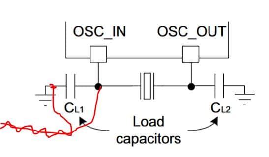
So looking on the schematic of the Blue Pill, there are 2 capacitors from the crystal , connected to ground. (C12 and C13)
Both are listed as 22pF. So I tried putting another 22pF in parallel with C13 and it seemed to lower the crystal frequency.
My current plan is to buy some variable capacitors, in the range of 10pF to 100pF, and replace C13 with the variable capacitor and see what range of values will work, because I know that that there is a limited range of capacitances over which the oscillator will run, and probably a smaller range where it will start up in the first place.
I recall some discussion about these capacitors for the F4 BluePill board, but don’t know if anyone worked out a usable range.
Trimming caps, temperature compensation (capacitors with various tempcos, varicaps, thermistors, etc).
Finally I pulled the trigger and acquired a 12MHz OCXO (vectron, used, small footprint) off the ebay ($20), removed the xtal from the counter’s board and coupled the OCXO’s output (HCMOS 5V) via a 33pF (via 20cm of RG-174) to the right point on the board.
Now my counter is stable within 0.1Hz (at 10MHz).
If you happy with a few Hz fluctuations under ambient temp (or when you do not want spend ~100mA for heating) do buy a TCXO .
It has no sense to mess with xtals.. I would never start with such an exercise again..
![]()
PS: Warning: do no use BP’s PLL multiplier when you keen on precise frequencies. It has got the saw-tooth issue..
They are a lot cheaper than spending a lot of time messing with trimmers and other semi-fixes.
https://www.ebay.co.uk/sch/i.html?_from … xo&_sop=15
One way to do it is to use a varicap – a reverse biased diode, a led, or mosfet, …, And use the mcu to generate a voltage for the varicap.
Alternative, you can also use a bunch of fixed cap and use the gpio pins to switch them in and out.
Endless possibilities.
It draws a few milliamps only, smd sizes available, best when you can somehow set the TCXO’s exact freq (built-in cap trimmer or external resistor/voltage (efc, VCTCXO), etc).
For long term stability a TCXO with GPS disciplining is a cheap/low_power variant too.
The OCXOs draw 1-3W for heating (even the smallest one).
But it depends on the requirements we do not know..
[Pito – Mon Jul 23, 2018 9:32 pm] –
…
But it depends on the requirements we do not know..
A good point, how accurate do these “various fairly accurate clock frequencies” need to be, and what do they relate to ?
The problem is not really the drift, its just that the frequency of those cheap crystals can be reasonably long way off frequency.
The clock generator is being used in a 30 year old, Ham radio HF transceiver, and they noticed that they have to tune about 200Hz lower than the real frequency, to resolve a lower side band signal. (I forgot which band they were on).
I’m not even sure if the main reference crystal in the radio is that accurate. It may be a TXCO but it may not.
It may just be a normal crystal with a trim capacitor on it.
I’m not sure if a TCXO is the ideal solution either, because for some output frequencies, ideally I need to pull the crystal higher or lower in frequency.
As that will allow me to generate an even wider range of frequencies.
Re: Varicap
Thats an interesting idea, for generating the wider range of possible frequencies.
@pito
PS: Warning: do no use BP’s PLL multiplier when you keen on precise frequencies. It has got the saw-tooth issue..
Interesting. I am using the PLL with a range of multipliers, and various timer dividers, to generate a large range of frequencies.
But I’ve not noticed any saw-tooth drift in the signal.
Anyway. I think I’ll try a trim capacitor across the crystal and then also try a trim capacitor on the caps to gnd and see what range of values I can get, and also what the stability of the crystal is, over a normal domestic temperature range
The saw-tooth drift’s amplitude is about 62Hz at 72Mhz..
The clock generator is being used in a 30 year old, Ham radio HF transceiver, and they noticed that they have to tune about 200Hz lower than the real frequency, to resolve a lower side band signal. (I forgot which band they were on).
30y old crystal may drift 30*5ppm because of aging. LSB/USB bfo offset is done against the last IF.
Btw, for ham radio I would highly recommend to build a dedicated oscillator (1-2 transistors), with low noise and good stability. Those MCU’s oscillators are crap.. Not for use in a ham radio rig.
Pulling a single 8MHz crystal with a varicap could be difficult when you target USB/LSB bfo usage.
With 2 Xtals in parallel (and say 10-20uH low Q inductor in series) you may achieve 10kHz pull when lucky. Even more, but the stability starts to follow ~LC.
If it is a case of the crystal being slightly off can’t you just set the HSE freq to match what the crystal really is??
or more importantly when doing the math for the timer (prescale and count) just simply do it based upon 800600 instead of 8000000???
wouldn’t doing it software be easier than playing with hardware??
When the application allows then Yes.
The accuracy achieved is the matter of math only when there is a headroom for it.
For example I’ve been using it in my DDS VFO’s.
When the freq resolution of a 32bit DDS is, say, 40mHz (milliHz) and you require 1Hz output signal accuracy, you can do it. It does not matter whether my master clock is 180.000.000,0 or 181.775.584,6Hz. It is important to know the master’s clock freq only.
Btw, I do not need to know the actual master clock freq.. I calibrate it such that I set VFO’s “10.0MHz” output freq, while measuring it with a precise counter at its output, and I rotate the freq dial knob (in a “calib mode”) such I see 10.000.000,0Hz on the counter’s display. The rotating the encoder’s knob is changing the master clock’s “sw value” accordingly (stored in EEPROM).
The same applies with your timers.
You have to analyze whether such a “sw math” adjustment does fit with your requirements actually.
PS: as a good example – there is a code (for PIC) I used to use for generating “long term precise” 1sec tick for watch..
It uses https://en.wikipedia.org/wiki/Bresenham … _algorithm and it works with any crystal frequency (ie 7.777.777Hz).
The only thing you have to know is that crystal frequency, and as precise as possible..
Thanks.
The BFO freq is only about 1.6kHz, so I presume the saw-tooth effect will be tiny, and sub audible ( which is probably why it’s not been noticed )
BTW. I have no idea why it the radio needs this freq for its BFO. I don’t actually own this radio, I am building the device for a friend.
Apparently the radio is supposed to have a crystal which is used to generate the BFO clock, but this was optional as it’s some sort of commercial radio, hence most don’t bave the LSB BFO crystal fitted.
Actually the project was initially to make a pseudo VFO for the radio by fooling it into thinking the frequency change buttons were being pressed , when in fact the user is turning a rotary encoder.
But we realised that the STM32 was capable of generating the BFO signal as well.
So it kills 2 birds with one stone.
[flyboy74 – Tue Jul 24, 2018 8:02 am] –
If it is a case of the crystal being slightly off can’t you just set the HSE freq to match what the crystal really is??
A potential issue with this is that the crystal frequency can vary with temperature and aging, which limits how well one can do with calibration.
Note that the “TXCO” mentioned in some posts above is a component that uses an integrated temperature sensitive compensation network to mitigate frequency drift with temperature. “OXCO” goes a step further in that the component has an integrated oven that keeps the crystal at an elevated and controlled temperature to desensitize it to the environment temperature. This obviously comes at the cost of the extra power to run the heating element.
I’ve never ever heard about 1.6kHz BFO freq. It could be it is “the offset” (the final IF used in a 30y old rig could be 455kHz, or 460kHz, or 4MHz, or 8MHz, or 9MHz or 10.7MHz, or something like that).
The BFO beats with the “final IF” (intermediate frequency, usually at the ~center of the SSB/CW filter), therefore your IF would be 0 or 3.2kHz in order to mess with SSB
PS: “final IF” – the radios use 1 or 2 or 3 or 4 IFs.
Crystals pullability varies but 5 to 10ppm per pf is about right for most high frequency crystals.
i’d think it is mainly to prevent situations of landing with crystals that doesn’t oscillate, that i’d think is a bigger bummer
a search on aliexpress for “epson crystal”
https://www.aliexpress.com/w/wholesale- … on+crystal
do turn up some entries
i’m seeing numbers like 12mhz, 16mhz etc, the specs as found on epson’s web site based on the part / sku number
https://www5.epsondevice.com/en/product … 002jf.html
https://support.epson.biz/td/api/doc_ch … JF&lang=en
the specs gives a tolerance of ±100 × 10-6 which probably is due to them being ‘simply the crystal’ with little if any temperature compensation
but i’d guess if it truly is from ‘epson’ the manufactured crystal frequency is more likely to be more precisely centered at those specific frequencies
while the aliexpress prices isn’t exactly exhorbitant, it is neither very cheap but still affordable in low quantities
e.g. one of the ad states $8.53 for 10 pieces
they may be worth trying if they are ‘sufficiently cheap’ as TXCO, OXCO are likely much pricier than simpler crystals like these,
the other way would be to buy the *cheapest* crystals
and hopefully the stochastics would land you with one that is perfect
the ‘cheap’ crystals goes for perhaps 70c for 10 pieces
https://www.aliexpress.com/w/wholesale- … ystal.html
(i was inspired by andy’s strategy viewtopic.php?t=594#p6129 with cheap crystals back then, and couldn’t resist the temptation & i did the same and got a bunch of *cheapest* crystal i found on ebay for the RTC, it turns out to be a good strategy and now i’d plug one in my mm/bp whether i’m using the RTC or not, amazingly simply soldering the 32k crystal there with no caps would still have a running RTC in LSE, I’d just let the time drift as i’m ok with even a couple minutes difference say in a month, i’d then sync it up with the desktop once in a while, my guess is if one bothers to program, one could even do ‘automatic’ adjustments say once in 24 hrs)
the keyword to search for cheap watch crystals turns out to be the number:
32768
and a whole bunch of them gets tossed up on ebay/aliexpress
p.s. i found the old thread
viewtopic.php?f=14&t=671
viewtopic.php?f=14&t=671&start=10#p27407
and some pictures
quality tuning fork crystal
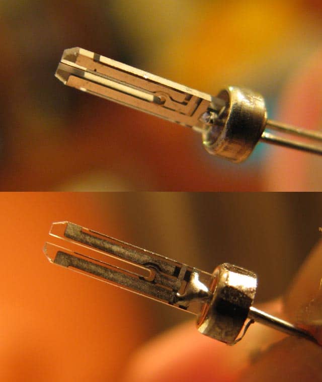
and an ‘ordinary’ crystal
i’d imagine the ‘epson’ ones may well be that quality ‘tuning fork crystal’
while the ‘cheap’ ones would more likely look like the latter
![]()
Crystals can be adjusted to exact frequencies by laser trimming. A technique used in the world of amateur radio for slight decrease of the crystal frequency may be achieved by exposing crystals with silver electrodes to vapors of iodine, which causes a slight mass increase on the surface by forming a thin layer of silver iodide; such crystals however had problematic long-term stability. Another method commonly used is electrochemical increase or decrease of silver electrode thickness by submerging a resonator in lapis lazuli dissolved in water, citric acid in water, or water with salt, and using the resonator as one electrode, and a small silver electrode as the other.
By choosing the direction of current one can either increase or decrease the mass of the electrodes. Details were published in “Radio” magazine (3/1978) by UB5LEV.
.. so the solution is simple, pop on the rubber gloves and break out the iodine crystals ![]()
Convert a 3D PRINTER To LASER ENGRAVER | Under 40$
we’d perhaps even be able to cut our own crystals, just that i’m not too sure if we’d be able to achieve the needed precision for the quartz to work correctly
[Pito – Tue Jul 24, 2018 12:07 pm] –
The BFO freq is only about 1.6kHz,
I’ve never ever heard about 1.6kHz BFO freq. It could be it is “the offset” (the final IF used in a 30y old rig could be 455kHz, or 460kHz, or 4MHz, or 8MHz, or 9MHz or 10.7MHz, or something like that).
The BFO beats with the “final IF” (intermediate frequency, usually at the ~center of the SSB/CW filter), therefore your IF would be 0 or 3.2kHz in order to mess with SSB
PS: “final IF” – the radios use 1 or 2 or 3 or 4 IFs.
Sorry.
I meant 1.6Mhz (1600kHz)
Still doesnt make much sense to me based on normal IF frequencies, but thats what it needs !
@ag123 – there are ceramic resonators and crystals. With 32kHz usually ceramic fork resonators. I had a 100kHz (or was it 10?) crystal in hand, it was as large as the Wrigley’s gum ![]()
@ahull: I did it during my early experiments – I opened the crystal package and tried to change its frequency – I did it with an eraser gum (pretty delicate operation – you remove the atoms off the crystal’s silver plating with the eraser gum). Touch the silver plating with it (extremely gently), clean it with alcohol, let it dry, measure the frequency, and so on in a loop. It worked.
1. or make some gimmick capacitors yourself; no cost and no shipping;
2. or use a diode as a varicap + trimmer;
3. use a vcxo – many tcxo’s are actually vctcxo.
I will try a gimmic capacitor. Several other people suggested the same thing to me, by using some 2 core speaker cable, cut to different lengths
With nothing attached to the crystal, its frequency seems to be around 7,999,9125 Hz (which is 87 Hz low) i.e about 10 ppm (parts per million) low
i.e The crystal is pretty good on the board I am testing with.
With 10pF in parallel, the frequency dropped to 96ppm low
20pF in parallel , it was 132 ppm low
47pF in parallel it was 174 ppm low
I don’t have any capacitors between that and 100pF, when I put 100pF in parallel the external oscillator would no longer run.
I tried a gimmick capacitor made from a 5cm piece of ribbon cable (just 2 stands), but the results where not as good as I had expected.
It only gave results equivalent to a few pico Farads (probably 3pF or less), and probably not enough to pull the crystal to exactly 8Mhz.
The other potential downside with this sort of gimmick capacitor is the relatively long length of wire that would be required, which could affect the oscillator circuit because of its inductance.
I presume some wire is more capacitive than others, but the ribbon cable I have, is not much use.
The STM32 I have to a friend of mine to put in his HF radio as a BFO generator, is 86ppm high. So by my calculations, he should be able to pull it back onto frequency, by using a around 10pF.
I think a neat solution to trimming the crystal is probably to buy a SMD adjustable capacitor, with a max value of either 10pf or in the worst case 20pF
The overall length of the capacitor appears to be 4.5mm which is almost identical to the distance between the pins on the crystal.
e.g.
http://www.farnell.com/datasheets/1825739.pdf
So I’ll probably try ordering something like that (probably from AliExpress as I can’t get them locally, without paying $$$ for postage)
a typical speaker cable would be too far apart – for the same capacitance you need a longer cable. I would use just two hook-up wires. or two pieces of aluminum foil rolled together if i need upwards of 20pf. you can trim it to your desired frequency.
A 10mm long gimmick capacitor made of 0.2mm magnet wire is ~10pF, 1pF/mm.
I used to use that while trying to get my original crystal in my counter right.
It works, you can trim it in ~tenth of pF.
Create a 15mm long gimmick and cut it slowly down with cutting pliers. Measure the freq.
0.5-1mm per cut max (switch off the BP when cutting).
See how it is made – mind the shot is not to scale, the wire is 0.2mm and the strand is 10mm long. So the whole capacitor is as large as this “I” on your screen ![]()
viewtopic.php?t=671&start=10#p27426
Twist it tighter for more pF/mm.
Do not waste money and time messing with cap trimmers, it has no sense..
PS: the crystals on the BP are quite temperature sensitive. So when soldering around or touching them with fingers they may walk 50-100Hz off. Using BP for something “precise and stable” is not a good idea, imo.
PPS: the tuning capacitor must always be wired to the BP oscillator’s INPUT. Double-check which side it is!
- Gimmick cap stm32 8MHz oscillator tuning.JPG (25.21 KiB) Viewed 241 times
I was using a capacitor across the crystal, rather than across one of the 2 existing capacitors.
I thought the norm was that to pull a crystal lower in frequency, a capacitor needed to be applied in parallel with it.
But, I will try putting a cap in parallel with the input pin into the STM32.
BTW. I think the schematic for the BluePill in the wiki is not correct, as it I think it shows the 2 caps as C12 and C13, however looking at my BluePill the they caps are C13 and C14
I know changing C13 made a difference to the frequency when I first started experimenting, but I just held a cap in my hand against the SMD cap on the PCB, so there were too many variables to know precisely what went on, apart from the osc frequency changed.
Re: Temperature sensitivity.
If I need it to be temperature stable I’ll need to use a TCXO. But ideally I need to pull the TCXO just a bit below its published freq of 8Mhz, as I need to pull the freq down by about 37ppm to around 7999700 Hz, in one case and potentially pull it a different direction in other cases.
Hence I like having the ability to pull a normal crystal a long way to be able to generate a wider range of freqs, using various PLL and divider setting.
i.e Since I don’t need USB, I can use any PLL setting (even overclocking is OK, since this is not for a “commercial” environment)
PS. This could all be done with a DDS, but the price is much more expensive for any of the DDS chips, and still needs some sort of micro controller to control the DDS
This solution using a STM32, is “good enough” for Ham Radio.
PS. I’m using the STM32 for other control purposes in the rig at the same time..
And I’m also wondering whether I can use it to replace the 32k byte EEPROM which holds the firmware for the main CPU in the radio
However, I think the EEPROM has 170nS access time, and I don’t think I’d be able to achieve that due to the latency in the interrupts.
But I think potentially the BluePill does have enough pins to mimic the operation of the EEPROM, and it would have enough spare flash to store the firmware for the radio.
Not good..

