Your use of the term, “very precise” makes me think that Arduino is not a viable core. Such things really need to be implemented in C or asm and outside of an environment that will have by design an interrupt at the system level for the micros() timer. Thus with interruptions at 1 uS you need to determine if you can work within the (phase) jitter on your PWM that would be introduced by the lower-level interrupt.
A better approach, IMO, would be a GPS receiver with a 1 PPS square wave output. Jitter is now in the low 2-digit nS range. Trigger your hardware dividers (phase lock loop is an option here) off of the leading/trailing edge and you have a relatively inexpensive approach, non-software, for generating a decent variable pulse width; you can then uses the hardware clocks to generate interrupts on a uC to manage capture, display, and other higher-level functionality.
There are also rather inexpensive dedicated chips for DDS these days… but I have not personally played in this sandbox.
Ray
the frequency used for PWM control in the PCA9685 is adjustable from about 24 Hz to 1526 Hz
the frequency used for PWM control in the PCA9685 is adjustable from about 24 Hz to 1526 Hz
There is a function called setPeriod(pwmPeriod_in_useconds) which returns a max_duty value. This maxduty value is important..
The function calculates internally values for a hw prescaler (1..65536) and also “timer_overflow” values, and it sets up the hw timer such it fits your pwm period values as best as possible.
For example>
maxduty = timer.setPeriod(20000);
sets the PWM period to 20ms (pwm freq=50Hz) and it returns for example maxduty=64515.
Thus you can go with your duty from 0..64515.
F4 Examples only:
pwmWrite(pwm_pin, x); // where 0<=x<=64515 for pwm period=20000us (50Hz)
pwmWrite(pwm_pin, x); // where 0<=x<=56000 for pwm period=1000us (1kHz)
pwmWrite(pwm_pin, x); // where 0<=x<=16800 for pwm period=100us (10kHz)
In F4 there is a bug in the setPeriod() function somewhere (not somewhere frankly – it calculates with a wrong clock_per_usecs value actually), so the pwm period I measured with my LA is twice (half the pwm frequency) of the one set by the setPeriod function..
Mind the maxduty depends on the pwm Period, so it is NOT always “65535” (ie only 16800 for pwm period=100usecs).
Here is the complete PWM source I messed with for the F407disco, it may work with F1 too..
http://www.stm32duino.com/viewtopic.php … 001#p11792
IMHO its not designed for precision. You can get it to be precise, but I would assume that it is not precise.
For precision, I suspect you would be better off using the STMCube to export code that just does the function you require, and not have all the things going on under the hood that the Arduino system hides from casual users.
Or like several people have suggested, use a separate dedicated PMW generator IC
Could you please name some of them ? The suggested only have 12 bit resolution as my requirement is in microseconds and milliseconds.
Like
200000uS Period(5Hz)
900uS Pulse Width
250000 Period(4Hz)
900uS Pulse Width
and like this. The range can go from 4Hz – 100Hz and Pulse Width can be 900uS to 100ms. See the difference ratio is way high between pulse width and period. I think 12 bit resolution will not work. Even 16 bit wont.
e.g. 1uS
Could you please name some of them ? The suggested only have 12 bit resolution as my requirement is in microseconds and milliseconds.
As an example I show you the above picture from my CubeMX clock configuration.
The APB1 Timer clocks needs to be 0.25 MHz (250 kHz) to get the 65535 period. That gives you a 262ms period length that is close to the 250ms you want. A small adjustment to the 65535 value will give you the exact 250ms period you want.
I used Timer 3 to run a few tests
htim3.Init.Period = 62500 gives you 250 ms period length = 4 Hz
htim3.Init.Period = 2500 gives you 10ms period length = 100 Hz
As other people suggested, you either have to use an additional chip to do that or use the CubeMX software to write the source code according to your needs because in my opinion, that case is something that goes out from the limits of arduino core.
This is what you get based on calculation the setPeriod() provides for you:
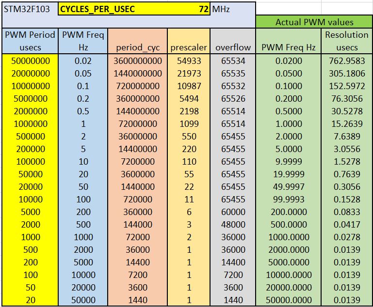
- F1 PWM.JPG (126.28 KiB) Viewed 3802 times
What they would be? Google seems no help. Could you please explain a bit about those 2.
Thank you.
PS: nvm I think they are some sort of components. Got more stuff on Google.
What they would be? Google seems no help. Could you please explain a bit about those 2.
Thank you.
PS: nvm I think they are some sort of components. Got more stuff on Google.
Nice catch Pito!
@DrBanana Some code to work on
const int pwmOutPin = PA1;

HardwareTimer pwmtimer(2);
void setup() {
pinMode(pwmOutPin, PWM);
pwmtimer.pause();
pwmtimer.setPrescaleFactor(220); //Prescaler
pwmtimer.setOverflow(65455); //Period width
pwmtimer.setCompare(TIMER_CH2, 32768); //Pulse width
pwmtimer.refresh();
pwmtimer.resume();
pinMode(pwmOutPin, PWM);
}
void loop() {
}
Besides the FPGA and other one seems to be another awesome way.
http://opencores.org/project,pwm
http://opencores.org/project,ptc
Generic VHDL implementation :
https://eewiki.net/pages/viewpage.actio … d=20939345
For CPLD, here is the general idea (although only 8 bits) :
http://dangerousprototypes.com/docs/CPL … _Generator
I’ve done such thing in past (in 199x), an 8 bits too, with GALs and TTLs…
Maple Mini.
const int pwmOutPin = PA1; // pin10

HardwareTimer pwmtimer(2);
uint16 maxduty, duty;
uint32 period, mypulse;
void setup() {
pwmtimer.pause();
period = 250000; // PWM period in useconds, freq 4Hz
maxduty = pwmtimer.setPeriod(period);
pwmtimer.refresh();
pwmtimer.resume();
pinMode(pwmOutPin, PWM);
}
void loop() {
mypulse = 23456; // 0<=mypulse<=period, this is the High pulse of my length in useconds
duty = map((int32)mypulse, 0, (int32)period, 0, (int32)maxduty);
pwmWrite(pwmOutPin, duty); // 0<=duty<=maxduty
while(1){};
}
http://opencores.org/project,pwm
http://opencores.org/project,ptc
Generic VHDL implementation :
https://eewiki.net/pages/viewpage.actio … d=20939345
For CPLD, here is the general idea (although only 8 bits) :
http://dangerousprototypes.com/docs/CPL … _Generator
I’ve done such thing in past (in 199x), an 8 bits too, with GALs and TTLs…
Back in these days, PALs been superseded by GALs (with EEPROM fuses), but than the CPLD and FPGA superseded them…
That make me think that I didn’t played with my Cyclone IV and Spartan6 FPGAs since more than a year …
Since then, I’ve upgraded my workstation OS, so I will have to re-install those respective IDEs, hoping with not much troubles.
Challenge ? 32 outputs individual PWM accessed by I2C Slave register map, syncrhonized with Zero-Crossing from 60HZ Main Power !
Yes, 32 Dimmers channels, like this 199x project, but with FPGA …
I recall working with GAL devices, but that was years ago ![]()
I’m actually building a dimmer using an STM32 at the moment, but not doing anything fancy. Just detect the crossing then use a hardware timer to delay the trigger.
So I have both a zero crossing and trigger ISR. I know if I dig into the docs, I don’t need to use a ISR for the zero crossing, I should be able to get a one short timer triggered by the zero crossing.
But I just wanted to get something working, and separate ISRs is easier.
Getting an effecient zero crossing detector is as complex as the software. I dislike the ones which just use 2 large (1 W) resistors to drive an opto. As the whole detector circuit gets hot. It’s also prone to spikes, miss-triggering the software.
So I’m using a more complex circuit I found on the web using a bridge, a transistor, a capacitor and some resistors.
It’s power usage is virtually nothing and it has a 3db low pass filter at 300hz, which helps suppress noise
http://libstock.mikroe.com/index.php?ur … calculator
I’ve not tried it, and Im sure you can do the same calculators in excel etc.
But it may be useful.


