Has anyone here done anything with Low-Power or sleep modes with the Maple Mini or similar clones? I am designing a device using STMF103C8T6 and a 2.4″ ILI9341 TFT. I want to turn off the display and put the device to sleep after a certain time of non-use. I have it working to turn off the display, and turning on using an interrupt on a button – but not having much luck finding any information on using Low Power modes. There are some examples on Leaflabs site using the same Sleep library as Arduino – but I have had no luck getting anything to work. Not so good with the low-level programming or library coding – more of a hardware guy…
The only thing I have found that does seem to work, at least reduces the CPU speed and power draw;
rcc_set_prescaler(RCC_PRESCALER_AHB, RCC_AHB_SYSCLK_DIV_256); //slows down cpu and reduces power
rcc_set_prescaler(RCC_PRESCALER_AHB, RCC_AHB_SYSCLK_DIV_1); /normal cpu speed
but when I use this occasionally the button interrupt to wake the device does not work consistently. This may be the way I have set up the interrupts…
Any help would certainly be appreciated!
Brent
http://forums.leaflabs.com/topic.php?id=1437
http://forums.leaflabs.com/topic.php?id=922
As you explore the possibilities, post back your experience.
ray
I am making something that will run on batteries and definitely reducing speed will help me, as I probably don’t need half the CPU power in this MCU.
EDIT: Those posts by Ray look promising.
I think you could use the systick to trip an interrupt every ms, check if there is something to do (like any input to process) and if not, go back to sleep.
The systick handler in libmaple has a function to set a callback function in your code, so once the interrupt trips besides incrementing the systick counter it will call your function to do whatever needed. You can also implement your own systick handler altogether.
If you have a look at the CoOS or FreeRTOS files, and search for systick, you will see how those setup the systick and systick callback.
I will try later to change CoOS and set the idle task to put the CPU to sleep when there is nothing to do and see if it works.
Anyone can suggest a measurable way to see if the CPU is sleeping much?
Anyone can suggest a measurable way to see if the CPU is sleeping much?
A small 1 Ohm resistor in series with the STM32 and use a scope to visualize the On/Sleep cycles by measurement of the Vd across the resistor.
On my Maple Mini, at full speed, the current is around 50mA, which would be a Vd of 165mV so a 1x probe should provide a decent indication while leaving 3.3 – 0.165 or 3.135V for the uC. If you are going to simulate a battery project, then I would recommend using the actual (fresh) batteries you intend on using, LiFePO4, Alkaline, etc. Chemistry will have an impact although I have not documented (anywhere I can find easily) what that will be. From a current measurement, you are not really overly concerned since you are looking for the deltas in current across the 1 Ohm resistor.
I wonder if the trick of reading the Arduino AVR battery voltage using the uC would work with the STM32… if so, once a critical voltage was reached you could do something: blink Power LED, display icon on 5110, turn off backlight, drop the uC speed further!
Ray
Seems like the current measurement may be the best. This can be a project to put the pig-o-scope to some practical usage too ![]()
I have a bunch of really low value 1/2W resistor that could eat 50mA for breakfast.
with 0.5ohm I calculate 25mV accross the resistor.
Andy, just have tested the pigoscope more, you think we have good sensitivity for 25mV?
I think I have some multimeter than is sensitive enough too.
I am planning on running something CPU intensive in the awake periods, then let it idle for a while and then repeat again.
Probably periods of several seconds will work the best.
Something like:
-CoOS
-Set idle taks to put CPU to sleep, which should be waken up in the next systick (1ms)
-1 Task only doing CPU math for 5 seconds.
-Then a delay of 5 seconds before running again. during that time the CPU should sleep for almost 1ms, wake up for very short, check that there is no other task to run, and go back to sleep.
Does something like that make sense as a measurable test?
P.S. I was thinking on doing IO to a display, but I think it would be better to measure just the CPU by itself, as an LCD can be put to sleep in other ways.
EDIT:
Ray, I am not sure how you are calculating 165mV with a 1Ohm resistor with 50mA across. I am missing something? that would give me 50mV accross the resistor. ![]()
For uC power down testing, the proof is in the actual code. Simulation will get you into the ballpark.
EDIT:
Ray, I am not sure how you are calculating 165mV with a 1Ohm resistor with 50mA across. I am missing something? that would give me 50mV accross the resistor. ![]()
I’m an idiot ![]()
My staff would never give me a calculator… especially RPN! 1-2-3 and Excel were all I had.
Ray
True story: A friend working for Tek long ago had a boss that ‘stole’ the desktop HP programmable calc, the one with the template overlays… He wrote templates and then marked-up with pencil the overlay for easy entry. The calculator sensed the particular template and knew which program to run. So, friend and colleges made an exact duplicate template carefully copying the boss’s handwriting – exact except that Pi was slightly skewed from the exact value of 3.141592654. When the boss would check a junior engineer’s work, the answer would be different. The boss would go out in the cube area to get the engineer and inevitably they would go back to the boss’s office. During this absence, one of the senior engineers would sneak in and swap the template on the calculator with the original template which of course gave the correct answer! They never got caught but had to stop the prank because the boss was getting very agitated that all the new engineers thought he was bonkers!
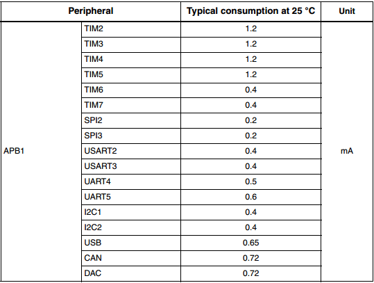
Are all peripherals initialized even if there arent used?
I’d guess using npn transistors for led & vcc for the screen and a ldo with low quiescent current would be good enough. you would only need to send the starting commands of the screen again.
If im wrong ,please tell me ![]()
You may want to read the datasheet. it got many infos about sleep and wakeup(isnt a0 even described as wakeup?)
~Straw
EDIT: This library (AVR specific) and the associated documentation should provide some useful insights. I have used it in the past for battery powered projects.
It may sound strange to think of 5mA in any context as hogging power, but where battery powered designs are concerned, it can mean the difference between days of standby battery power and weeks, months or even years. If you can reduce current from 5mA to 500uA then obviously your battery lasts 10 times as long on standby, so your little 120mAh lipo that lasts 1 day between charges becomes a more useful device that goes 10 days before you need to recover it and recharge. A 2000mAh lipo goes from 16 1/2 days to 167 days of standby, and my “Sticks O Dynamite” battery pack lasts forever or thereabouts ![]() (theoretically, assuming the average lifespan of a modern commercial product) . Hence my comment about removing the power LED.
(theoretically, assuming the average lifespan of a modern commercial product) . Hence my comment about removing the power LED.
The example in the first link from Ray’s post compiles and toggles the led with a few modifications, since we got rid of toggleLed and a few more things. I think we should not have removed those, now to use all examples you need to go adding them to the sketch
Anyway, if you press the button twice, it turns the led off, another 2 times turn it on. I still have to power it thru a resistor and calculate comsumption:
The notes about serialusb and the rest were there already. I have not verify if it works or not yet besides toggling the pin.
// Engages stop mode on the cpu, wakes up when the onboard button is briefly pressed

// Toggles pin 3 and pin 13 every time the button is pressed/released

// Pin 3 is used to indicate that the main loop has run. It is toggled every time loop() is called.

// Normally this would be constantly flashing on/off so fast it would appear on all the time

// In this case, the loop is only finished when the button has been pressed/released.
// PROBLEMS so far : works as expected,
// : note that because it's in stop mode, you may have to
// : reset to reprogram.
// : SerialUSB.print : NOT WORKING.
#include <stdint.h>
#include <libmaple/pwr.h>
#include <libmaple/scb.h>
#define BOARD_LED_PIN 33
#define BOARD_BUTTON_PIN 32
#define BUTTON_DEBOUNCE_DELAY 1
// These are possibly defined somewhere but I couldn't find them. System Control Register
#define SCB_SCR_SLEEPDEEP 4 // Controls deepsleep(1) or sleep(0)
#define SCB_SCR_SLEEPONEXIT 2 // Controls sleeponexit (not used here)
volatile bool ledState = LOW; // Used in ISR blinkState()
void togglePin(uint8 pin) {
if (pin >= BOARD_NR_GPIO_PINS) {
return;
}
gpio_toggle_bit(PIN_MAP[pin].gpio_device, PIN_MAP[pin].gpio_bit);
}
void toggleLED() {
togglePin(BOARD_LED_PIN);
}
uint8 isButtonPressed(uint8 pin=BOARD_BUTTON_PIN, uint32 pressedLevel=HIGH) {
if (digitalRead(pin) == pressedLevel) {
delay(BUTTON_DEBOUNCE_DELAY);
while (digitalRead(pin) == pressedLevel)
;
return true;
}
return false;
}
uint8 waitForButtonPress(uint32 timeout=0) {
uint32 start = millis();
uint32 time;
if (timeout == 0) {
while (!isButtonPressed())
;
return true;
}
do {
time = millis();
/* properly handle wrap-around */
if ((start > time && time + (0xffffffffU - start) > timeout) ||
time - start > timeout) {
return false;
}
} while (!isButtonPressed());
return true;
}
void setup()
{
pinMode(BOARD_LED_PIN, OUTPUT);
pinMode(3, OUTPUT);
pinMode(BOARD_BUTTON_PIN, INPUT);
// Just to show that the board has reset (wdt or possibly standby mode(not used here))
for (int i = 0; i < 20; ++i)
{
delay(200);
toggleLED();
}
togglePin(3);
// Wake up cpu on button press.
attachInterrupt(BOARD_BUTTON_PIN, blinkState, FALLING);
}
void loop()
{
//SerialUSB.println("HI!"); delay(100); // Only works on first iteration, before stop mode
// Clear PDDS and LPDS bits
PWR_BASE->CR &= PWR_CR_LPDS | PWR_CR_PDDS;
// set sleepdeep in the system control register
SCB_BASE->SCR |= SCB_SCR_SLEEPDEEP;
// Now go into stop mode, wake up on interrupt
asm(" wfi");
digitalWrite(BOARD_LED_PIN, ledState);
togglePin(3);
}
// Interrupt Service Routine (ISR)
void blinkState()
{
ledState = !ledState;
waitForButtonPress(); // Dangerous in ISR, I know, but quick demo only so blah.
}
Sleep mode – 2.892mA
CPU scaled 256 – 15.954mA
No Sleep or Scale, TFT off – 48.26mA
TFT on – 89.85mA
The device is running off a single 2000mah Lion battery. I am using a Buy-Display.com 2.4″ ILI9341 TFT (without shield), my board has both 2.8 and 3.3v regulators (LP3981), a MCP73831 battery charger, DS3231M RTC, EEprom ic, TCS2046 touch controller, BMP180, SHT21, mosfet circuit for checking battery voltage, piezo buzzer and a BT module – I have disabled the buzzer, mosfet circuit, and BT module for the tests, but nothing else so far.
Will do more tests and update post when I have time.
~Straw
According to the datasheet it should be possible to get the processors power down to around 6uA with a further 3uA or less for the RTC and battery backed registers. This is with absolutely everything shut down, but presumably this case the processor would have to backup and restore all clocks etc.
As to creating a useful set of library functions for this, I’m open to suggestions. Sleep till a certain time, sleep for n seconds, sleep till interrupt from (event/pin transition) all seem worth while goals.
One concern is that the deepest sleep mode does not keep the RAM. So to achieve 9uA we may need to use an external memory eeprom or flash to save the state. I just recently discovered FRAM memories, which don’t need power to keep data, but are completely random read and write like SRAM, with much lower power requirements to write as it doesn’t need to erase whole pages at once.
They are available in parallel, i2c and SPI interfaces. Seems like a lower power option for permanent storage. Save all the important information there, go to sleep, when waking up check if there is a state to restore, and then run from that state.
My understanding is that the power domain for the RTC/Ram is separate from the processor, so you can elect to shut it down separately, or not depending on your application (hence the separate 3uA figure for the RTC/Ram), but I’ll re-read that part of the datasheet to make sure I am not barking up the wrong tree.
I was having a good look at the datasheet, and seems like putting the MCU in deepsleep (clocks are lost, all peripherals shutdown, but RAM is kept) can bring the current down to 14uA to a max of 340uA. The next mode would be standby, that loses RAM.
If we can make a library that saves the state of the peripherals and the clocks in RAM, and then put the chip in deepsleep mode, and upon wake up restores the clocks an peripherals, I think it could achieve huge savings for any sketch that needs to keep RAM.
I agree, the scenario you describe would probably be the most useful mode. Deepsleep would only be required for extreme cases (very long sleeps, or relatively small backup batteries).
~Straw[/quote]
The idea is saving the state of all the peripheral clocks so after the sleep mode stops them all, on wake up you can restore the same settings.
Of course you can just go and run the initial setup of clocks as if the system was just booting from reset, but what happens then if your sketch has been purposely stopping some clocks or reducing the speed on others?
I understand the deep sleep mode does not preserve the status of the main clock at the very least:
“When exiting Stop mode by issuing an interrupt or a wakeup event, the HSI RC oscillator is
selected as system clock. “
-Using sleep mode (not deepsleep/stop), I can keep using serialusb, etc when the MCU wakes up right away. The clock is still HSE on wake up. Current reduction is negligible, around 0.5mA less than running only.
-Using deepsleep I can setup HSE, PLL, etc when the MCU wakes up, and go back to using the HSE. I did not try the peripherals, but I suspect I may just need to re-enumerate USB. I would expect the rest to work. The datasheet only says the clock source goes to HSI but does not say anything about losing peripheral clock settings. Systick can not be used in this mode.
-Using the frequency division I can go down to DIV16 and still have the MCU respond to a button, but any lower than that it seems like I lose a lot of button pushes. May work better for other interrupts sources like the RTC. The current reduction is significant, I forgot to write down the numbers, but I think at div16 I was using around 1/10 the mA compared to full speed.
Conclusions for me:
-Deepsleep is the best if you need to seriously save energy, but we need to set the MCU back to using the Xtal, and some peripherals may need to be reset to.
-Sleep by itself seems to have very little effect, but causes no impact to anything. It may be helpful combined with shutting down clock to several peripherals.
-Setting a prescaler to up to DIV8 seems like a good way to save energy if your sketch doesn’t need the extra speed. The speed grows faster than the current usage (or reduces faster than the reduction in current), so as Andy mentioned, it may be better to complete a task quickly and then go to deepsleep. If you task is waiting for anything like a button or processing some slow input, then a reduction in speed may be a pretty good way to save power.
-I belive the most saving in deepsleep mode comes from shutting down peripheral clocks. For anything running on batteries we should shutdown all unused peripherals right away, as libmaple initializes the clock to pretty much everything on start.
So the tactic for me will be:
-Shutdown clock to anything not needed
-Set the prescaler division to the one that completes the tast the fastest without being so fast that I need to wait on something else.
-Deepsleep as soon as possible.
I copied the code to set the HSE and PLL and select HSE as clock from the libmaple init routines and worked fine. Whenever I have more time I will see if I can test some peripherals after deep sleep, like SPI, serial.usb(after re-enumeration) and see if they need some other reset or not.
Did you had the time to perform some other tests?
As my approach to reduce power is to deactivate unused peripheral would like to know about your results and maybe some direction to follow.
All the best,
Tim

