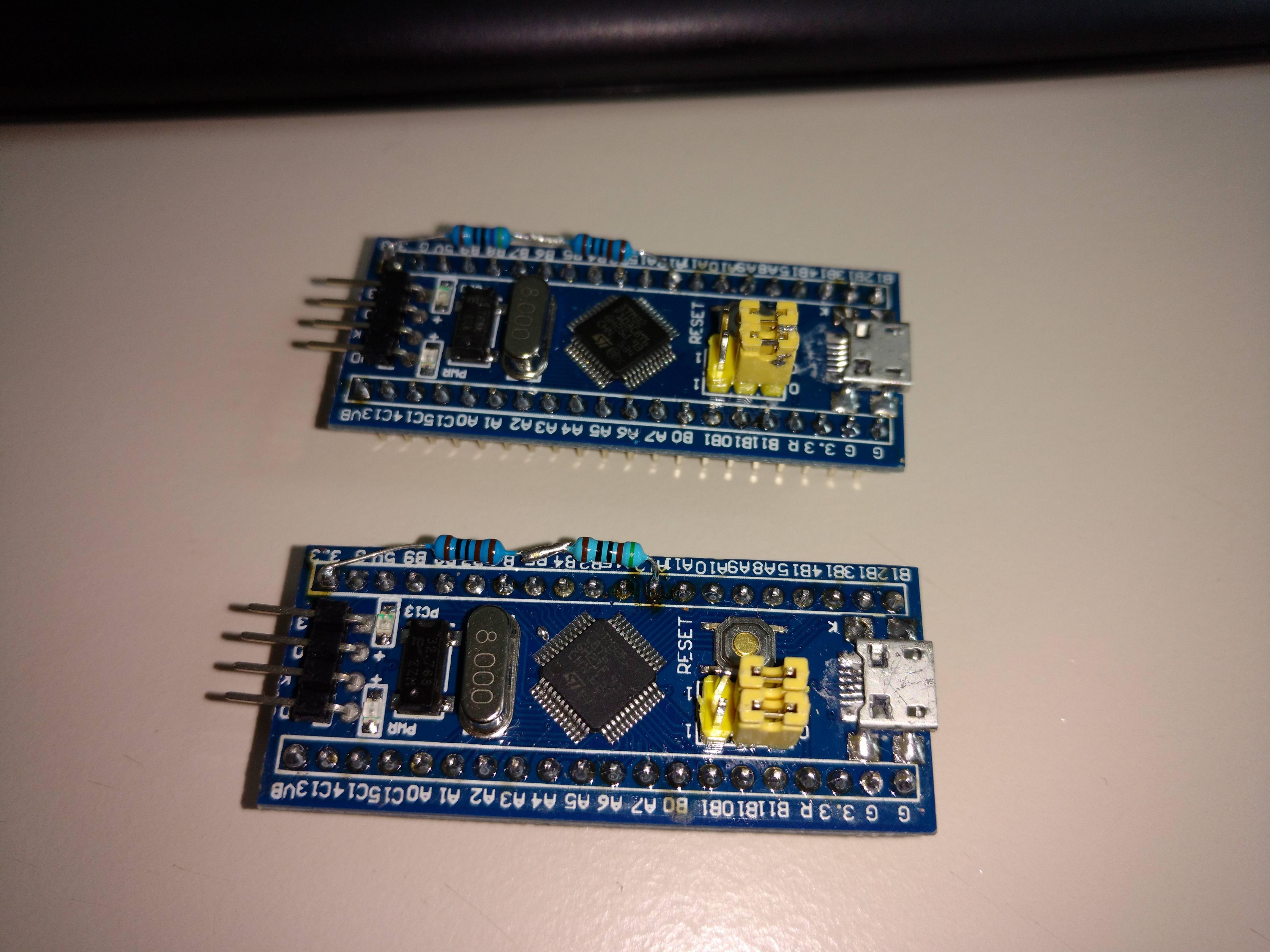
I have two blue-pill SMT32 boards. I flashed them with the STM32duino-bootloader and uploaded a Blink sketch with Serial.begin(9600);
I desoldered the R10 resistor. I tried to replace it with a 1,5kohm resistor but still I cannot get usb to work. It give me an error about that device description failed (Error 43). It’s the same error with the 10kohm resistor in place.
Then I tried putting multiple values ranging from 1kohm, 1,8kohm, 2kohm, 3,3kohm to 4k7ohm between PA12 and 3.3V. Still the same error occurs.
What am I doing wrong or what am I missing here? It happens on both the boards.
To summarize:
– Uploading sketches using a CH430G works properly.
– I can get serial output from the blue-pill using a CH430G.
– I cannot use the micro usb port for data. Only for charging because I get an error 43 on Windows even after changing the resistor.
Lennyz
[stevestrong – Fri Jun 30, 2017 2:00 pm] –
Try resoldering all usb pins, the original soldering can be faulty.
I tried your suggestion but still the same error occurs. As far as I can tell form my magnifying glass the connections are good.
If you selected upload via external USB to serial, the sketch will not have USB enabled ( but the bootloader will)
Send a link to the boot loader version you loaded ( via USB serial), if it’s the wrong one, it won’t work
it would tell you if it’s that the whole lot is dead or just the usb.
if you have a uno or nano you could use that as a serial interface ( good for something still ![]() )
)
i once had a shield that switched d0/d1 between normal and the shield device.
srp
[ahull – Fri Jun 30, 2017 4:02 pm] –
What operating system are you using?
Windows 10 x64
[RogerClark – Fri Jun 30, 2017 10:40 pm] –
How did you upload a sketch if USB is not working ?If you selected upload via external USB to serial, the sketch will not have USB enabled ( but the bootloader will)
Send a link to the boot loader version you loaded ( via USB serial), if it’s the wrong one, it won’t work
Uploading worked fine using a CH430G for the USB to serial. The sketch also runs properly and serial output works through the CH430G. I cannot get Windows from properly initiating the device even after changing the resistor on R10. I flashed this file for the bootloader:
“generic_boot20_pc13.bin”
I can only use the micro usb port on the blue-pill for power but not for data.
[zmemw16 – Fri Jun 30, 2017 10:44 pm] –
if you have a st-link, try programming that way and do a sketch writing to the serial ports.
it would tell you if it’s that the whole lot is dead or just the usb.if you have a uno or nano you could use that as a serial interface ( good for something still
)
i once had a shield that switched d0/d1 between normal and the shield device.srp
The boards work fine. I am able to successfully upload sketches using a CH430G. It’s the micro usb port on the blue-pill that I would like to use. Thus far I can only use it for power but not for data.
If yes, then the bootloader is active, otherwise you have to upload it again.
Uploading over USB to serial adapter (your CH430G) will overwrite everything inside the chip, the previously flashed the bootloader too.
So first upload the bootloader (with CH430G), then change the upload method in Arduino IDe to “STM32duino Bootloader 2.0”. This will force the IDE to use the DFU upload tool for flashing instead of the serial adapter.
If this does not help, try to re-solder the USB pins.
[stevestrong – Sun Jul 02, 2017 3:08 pm] –
How did you flash the bootloader? Are you sure that the bootloader is on the chip? Do you see the LED blinking faster 3 times after reset?
If yes, then the bootloader is active, otherwise you have to upload it again.Uploading over USB to serial adapter (your CH430G) will overwrite everything inside the chip, the previously flashed the bootloader too.
So first upload the bootloader (with CH430G), then change the upload method in Arduino IDe to “STM32duino Bootloader 2.0”. This will force the IDE to use the DFU upload tool for flashing instead of the serial adapter.
If this does not help, try to re-solder the USB pins.
I flashed the bootloader using this command:
stm32flash.exe -w generic_boot20_pc13.bin COM21
This is the output:
http://stm32flash.googlecode.com/
Using Parser : Raw BINARY
Interface serial_w32: 57600 8E1
Version : 0x22
Option 1 : 0x00
Option 2 : 0x00
Device ID : 0x0410 (Medium-density)
– RAM : 20KiB (512b reserved by bootloader)
– Flash : 128KiB (sector size: 4×1024)
– Option RAM : 16b
– System RAM : 2KiB
Write to memory
Erasing memory
Wrote address 0x08001c14 (100.00%) Done.
After that when I attach the microusb port to my pc, I get an error message 43 on Windows. The STM32 is not attached to any COM port. I can flash sketches with the CH430G but not through the microusb port because of the error.
I think I will trow them away and spend a few euro’s more on a proper stm32 board.
Can you try it on a W7 or W8 machine, or linux or OSX
[RogerClark – Mon Jul 03, 2017 7:05 am] –
Hard to know if this is a HW or drivers issueCan you try it on a W7 or W8 machine, or linux or OSX
I have tried it on an OSX and on Linux mint. On all of them the boards don’t show up.
Did the LED flash when you apply power.
If so, and it does not work on USB, its probably a bad soldering on the USB connector. This has been very common recently with many people having this problem
[Lennyz1988 – Mon Jul 03, 2017 6:55 am] –
After that when I attach the microusb port to my pc, I get an error message 43 on Windows.
Have you followed the driver installation procedure?
[Lennyz1988 – Mon Jul 03, 2017 6:55 am] –
The STM32 is not attached to any COM port.
That’s normal, but a DFU device should appear in the device manager, after you installed the drivers (see above).
This allows the flashing of any further software through the USB port.
The COM port appears only after the first successful upload through the USB DFU.
[Lennyz1988 – Mon Jul 03, 2017 6:55 am] –
I can flash sketches with the CH430G but not through the microusb port because of the error.
First install drivers, restart the PC.
Then flash the bootloader and change back the BOOT0 jumper to original position.
Finally change in Arduino IDE the upload method to “STM32duino bootloader 2.0”. Upload a blinky sketch.
If this does not work, then buy a new blue pill. Several users are using these boards, it should work for you, too.
[stevestrong – Mon Jul 03, 2017 12:08 pm] –[Lennyz1988 – Mon Jul 03, 2017 6:55 am] –
After that when I attach the microusb port to my pc, I get an error message 43 on Windows.Have you followed the driver installation procedure?
[Lennyz1988 – Mon Jul 03, 2017 6:55 am] –
The STM32 is not attached to any COM port.That’s normal, but a DFU device should appear in the device manager, after you installed the drivers (see above).
This allows the flashing of any further software through the USB port.
The COM port appears only after the first successful upload through the USB DFU.[Lennyz1988 – Mon Jul 03, 2017 6:55 am] –
I can flash sketches with the CH430G but not through the microusb port because of the error.First install drivers, restart the PC.
Then flash the bootloader and change back the BOOT0 jumper to original position.
Finally change in Arduino IDE the upload method to “STM32duino bootloader 2.0”. Upload a blinky sketch.If this does not work, then buy a new blue pill. Several users are using these boards, it should work for you, too.
Thank you! I had misinterpreted the instructions. I always flashed a “Blink” sketch after I had uploaded the bootloader through serial (CH430G). I didn’t understand that I shouldn’t have done that. You told me the same thing a few posts back, but then I tried it with BOOT0 = 1. With BOOT0=1 I still had the error43. But now with BOOT0=0 I could flash both the STM32’s through the IDE using the microusb port.
Thank you everyone for your and time help. The results ![]()
Please insert to the thread title “[SOLVED]” if it works now.
![[SOLVED] Discovery STM32F100RB — Trouble with timers and library structure](https://sparklogic.ru/wp-content/uploads/2019/11/st-stm32vl-discovery-90x90.jpg)
