I was flashing maple mini with st-link clone and st-link utility. I was facing problem while flashing. I got following some error
16:26:02 : Some flash sectors are write protected.

The write protection will be disabled then restored after flash programming

in case there is no option bytes segment within the file.

16:26:05 : Programming error @ 0x0800001C!
I encountered a similar issue a while back – This -> https://github.com/rogerclarkmelbourne/ … from-Linux <- might give some clues.
In particular I think the line …
NOTE: If the chip flash is protected, you may also need to issue a “stm32f1x unlock” command.
… might be of importance. It was a while ago, so I doubt if I can recall what all else I tried, when attempting to address my issue, and your problem may be subtly different.
Just remove the write protection with st-link if you dont need it, and reflash the bootloader.
I opened serial terminal and got following messages continously.
Congratulations, you have installed the STM32duino bootloader

See https://github.com/rogerclarkmelbourne/STM32duino-bootloader
For more information about Arduino on STM32
and http://www.stm32duino.com
After some reading on STM32duino’s wiki page i am really confused.
I tried maple_rev5_boot20.bin, generic_boot20_pb12.bin as well.
i am using stm32f103c8t6.
but result is same. not able to flash over usb bootloader.
For the maple mini, there is no upload method option using Stlink, Black Magic Probe, or Serial. This is for good reason, if you upload using any of those methods, it is going to overwrite the bootloader and you won’t be able use the normal upload method people expect the Maple Mini to use.
So people resort to using the generic stm32f103 entry. However, you can’t really use the generic board selection because the USB reset circuitry for the Maple Mini and the Generic boards are incompatible. Also all the pin numbers will be wrong and the Maple Mini doesn’t have the PAnn, PBnn, or PCnn pins marked. So you have to get out the datasheet and schematics to use it.
You can make a maple mini work with the stlink device. However, you have to modify the boards.txt entry for the maple mini or make a new one.
Simply flash that binary with ST_Link into the MM (erase the entire chip/flash/verify).
Select Maple Mini when building the sketch. Select the “stm32duino bootloader” as the upload method. Select the port with your COMx.
It will upload/connect (usb serial) automatically.
@Rick, I was facing problem while flashing using stlink utility but i could flash using arduino ide.
But after flashing USB bootloader, i couldn’t flash using STM32duino bootloader. i used this method before(6 months ago).
@pito, i tried suggested binary too. But not working for my board. Board is detected as COM port but not able to flash the code using usb bootloader.
Do you use the Maple Mini board? Post a link to your board, plz.
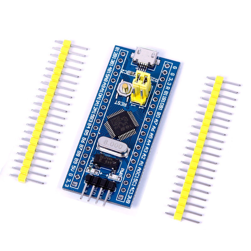
- STM32Mini (1).jpg (132.99 KiB) Viewed 402 times
Hi,
I was flashing maple mini with st-link clone and st-link utility
You indicate from very beginning your board is Maple Mini..
That is the BluePill board..
This is the binary for your board:
https://github.com/rogerclarkmelbourne/ … 0_pc13.bin
i know some threads were going on about name of boards.
yes. I have blue pill board.
Tell us exactly what is the problem during flashing the bootloader binary with the ST_Link Utility.
We’ll try to help you, you have to describe in detail what you have done so far.
The flashing the bootloader with the ST_Link is easy.
Do not power the board from both BP usb and ST_Link, choose only one of them. Use 3.3V only (ie. from ST_Link dongle do use 3.3V).
Sometimes the ST_Link Utility cannot connect. Select Target->Settings->Mode – “Connect under Reset” and press reset button on the BP immediately after you click Target->Connect.
I flashed binary you mentioned. and flashing code as
// the setup function runs once when you press reset or power the board

void setup() {

// initialize digital pin PB1 as an output.

pinMode(PC13, OUTPUT);

}
// the loop function runs over and over again forever
void loop() {
digitalWrite(PC13, HIGH); // turn the LED on (HIGH is the voltage level)
delay(100); // wait for a second
digitalWrite(PC13, LOW); // turn the LED off by making the voltage LOW
delay(300); // wait for a second
}
Stop messing with Arduino sketches, unless you have flashed the bootloader successfully.
How do you flash the bootloader with “ST_Link dongle”?
Do you use the ST_Link Utility in order to flash the bootloader??
What errors you get when flashing the bootloader??
What do you see on the BP LED after you flashed the bootloader?
[dev – Sun Nov 12, 2017 6:57 pm] –
ohh…yes. Sorry for that. But i did mentioned stm32f103c8t6.
“A rose by any other name would smell as sweet”…
Maybe those words ring true with Shakespeare and love. Unfortunately, the name of the board is important here. I hate wasting my time on this kind of confusion. Why do people find it so hard to identify what they are using?
@Roger, what should i check in that? i think usb is detecting as COM port then USB is working. (i have no idea if other problem exists)
@Pito, I am not messing around with any sketches. I am just using LED blink example and some pre compiled binaries to get usb bootloader working.
Yes, I am using STlink utility to flash binaries? Should i try with serial method?
if i use stlink utility and stlink dongle then i get error as follows.
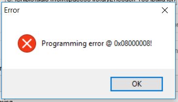
- error.JPG (17.53 KiB) Viewed 252 times
2. when using ST_Link dongle with ST_Link Utility then the programming the bootloader fails with above errors.
Is that correct?
Could you make the screenshot of your Target->Settings while connected to your ST_Link dongle?
2. when using ST_Link dongle with ST_Link Utility then the programming the bootloader fails with above errors.
yes, right.
Could you make the screenshot of your Target->Settings while connected to your ST_Link dongle?
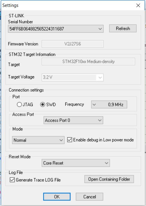
- settings.JPG (51.88 KiB) Viewed 225 times
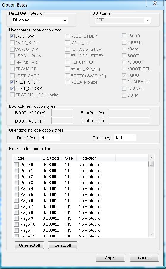
- BPill Option Bytes.JPG (107.61 KiB) Viewed 220 times


