If anyone has used One-Pulse mode, could you let me know
I need this for one of my personal projects, so I’m attempting to write the code for it and add to the core
In One Pulse mode, an external signal can be used to trigger one of the timers, which in turn creates a pulse after a specific delay, with specific duration
Let’s use TI2FP2 as trigger 1:

• Map TI2FP2 on TI2 by writing CC2S=01 in the TIMx_CCMR1 register.

• TI2FP2 must detect a rising edge, write CC2P=0 in the TIMx_CCER register.

• Configure TI2FP2 as trigger for the slave mode controller (TRGI) by writing TS=110 in

the TIMx_SMCR register.

• TI2FP2 is used to start the counter by writing SMS to ‘110 in the TIMx_SMCR register

(trigger mode).

The OPM waveform is defined by writing the compare registers (taking into account the

clock frequency and the counter prescaler).

• The tDELAY is defined by the value written in the TIMx_CCR1 register.

• The tPULSE is defined by the difference between the auto-reload value and the compare

value (TIMx_ARR - TIMx_CCR + 1).

• Let us say user wants to build a waveform with a transition from ‘0 to ‘1 when a

compare match occurs and a transition from ‘1 to ‘0 when the counter reaches the

auto-reload value. To do this enable PWM mode 2 by writing OC1M=111 in the

TIMx_CCMR1 register. The user can optionally enable the preload registers by writing

OC1PE=1 in the TIMx_CCMR1 register and ARPE in the TIMx_CR1 register. In this

case write the compare value in the TIMx_CCR1 register, the auto-reload value in the

TIMx_ARR register, generate an update by setting the UG bit and wait for external

trigger event on TI2. CC1P is written to ‘0 in this example.

In our example, the DIR and CMS bits in the TIMx_CR1 register should be low.

User only wants one pulse (Single mode), so write '1 in the OPM bit in the TIMx_CR1

register to stop the counter at the next update event (when the counter rolls over from the

auto-reload value back to 0). When OPM bit in the TIMx_CR1 register is set to '0', so the

Repetitive Mode is selected.
PWM is working OK because I can test the values using
const uint16_t pulseDelay=250;

const uint16_t pulseWidth=1000;

pinMode(PA1,PWM);// Timer 2 channel 2 output pin

Timer2.setPrescaleFactor(72);

Timer2.setCompare(2,pulseDelay);// Delay value

Timer2.setOverflow(pulseWidth + pulseDelay-1);
	// counter setup in one pulse mode, as slave triggered by TI1

TIMER2_BASE->CR1  = ( TIMER_CR1_OPM ); // one pulse mode

TIMER2_BASE->SMCR = ( TIMER_SMCR_TS_TI1FP1 | TIMER_SMCR_SMS_TRIGGER );Wow…
Thanks
I will test it on my mains dimmer board.
BTW.
On a slightly different subject…
I am not sure if perhaps the Input Capture may not function absolutely correctly
At the moment I need to store the last counter value recorded by the ISR and subtract it from the current value.
So the counter may actually be free runnnig.
I am using code supplied by @cesco but perhaps he omitted something to hold the count and also to reload with 0 at the start of the input pulse.
I’ve tried the code but its not doing what it should be ![]()
On the rising edge of PA0, PA1 toggles state
I tried changing the setCompare and the setOverflow but it didn’t make any difference
I think this is closer to what its supposed to be doing, but it doesnt seem to be quite working yet ![]()
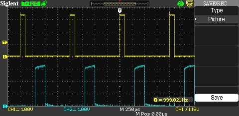
- Timer input capture – one pulse mode.jpg (45.1 KiB) Viewed 2203 times
BTW.
I see what you mean about not setting up the mode at all
TIMER2_BASE->CR1 = ( TIMER_CR1_OPM ); // one pulse mode
The instructions to do that were in a completely different paragraph in the manual
Also.
I see that you were using the Timer3 output on PA6
I’ll change my hardware and try that
I still don’t see much benefits in going one pulse here. A good old timeout will do.
I got it working
#include <Streaming.h>

uint16_t pulseDelay = 3000;

uint16_t pulseWidth = 100;

void setup()

{

pinMode(PA1, PWM);  // setup PA1 (Timer2 channel 2) to PWM (one pulse mode)

pinMode(PA0, INPUT);  // setup PA0 (Timer 2 channel 1) as input (capture input mode)
Timer2.pause(); // stop the timers before configuring them
timer_oc_set_mode(TIMER2, 2, TIMER_OC_MODE_PWM_2, TIMER_OC_PE);
Timer2.setPrescaleFactor(72); // 1 microsecond resolution
Timer2.setOverflow(pulseWidth + pulseDelay-1);
Timer2.setCompare(TIMER_CH2, pulseDelay);
// counter setup in one pulse mode, as slave triggered by External input for Timer 2
TIMER2_BASE->CR1 = ( TIMER_CR1_OPM ); // one pulse mode
TIMER2_BASE->SMCR = ( TIMER_SMCR_TS_ETRF | TIMER_SMCR_SMS_TRIGGER );
TIMER2_BASE->CCER = ( TIMER_CCER_CC1E | TIMER_CCER_CC2E ); // enable channels 1 and 2
Timer2.refresh(); // start timer 2
Timer2.resume(); // let timer 2 run
}
void updateDelay(uint16_t dly)
{
Timer2.setOverflow(pulseWidth + dly-1);
Timer2.setCompare(TIMER_CH2, dly);
Timer2.refresh(); // start timer 2
}
char buf[16];
char *bPos;
void loop()
{
if (Serial.available())
{
bPos=buf;
while(Serial.available())
{
*bPos++ = Serial.read();
}
*bPos++='\0';
updateDelay(atoi(buf));
}
}
I think you triggers the load “on” at zero crossing, and at specific time you switch off the load (with the pulse). Based on the timing you manages the power.
Does it creates EMI as well when switching off during an active period (off the zero)?
Would not be better to regulate the power by switching on/off at zero crossing? I mean by counting sine periods (like 100 periods = 1kW, 1 period = 10W)..
I would do it this way, assuming you want pam:
1) initialize the timer into one pulse mode, and interrupt at the top.
2) set up the compare to be 1 (or 0 if it works), and the top to be a value designed for the right amount of power;
3) in the isr, zero its counter, and update the top.
so the timer will be started by the zero-crossing signal, the OC pin is fired right away, and goes low at the top.
as you can see, the one-pulse mode isn’t that useful: the same thing can be done by a exti pin + the timer in overflow mode.
For a triac, it’s the other way around. The triac turns off at zero crossing and needs another trigger after some time delay to set the phase angle. A new trigger is needed for each half-cycle.
One pulse is working fine for me.
One additional benefit of the one pulse is that the ON period of the pulse can also be controlled.
So in my case, with the AC Dimmer, the ON period is fixed at 100uS.
The LED in the opto-triac used as the driver for the “power triac”, actually has a limited life (according to the spec from some manufacturers). They recommend that you use as low current as you can reasonably get away with to maximise LED life.
For the MOC3021 I think this value around 10 – 15mA , i.e at least 10mA but they don’t recommend you run the LED at its max of 50 or 60mA as this will shorten the operational life.
Hence only using a short “ON” pulse will conserve the LED lifespan.
I was originally turning turning on the triac after the delay period and then turning the output off when the STM32 got the next zero crossing ISR.
This is because the zero crossing detector pulse is actually quite wide in my case.
The pulse goes low around 600uS before zero and rises again around 600uS after zero.
But this has 2 disadvantages…
I can’t trigger the triac in the last 600uS of each cycle, as this is after the time I’ve already turned the triac off, and I have no other way to turn it off before the zero crossing…
Using on pulse, allows me to turn it on, up to 101us before the real zero crossing point.
This allows for very low power operation, e.g less than 5W on a 4kW load.
I admit that this , super low power operation, is not that important, but I get it for free using One-Pulse…
an interesting concept. I haven’t seen people trying it however. I can see it being quite useful when emi is of paramount concern.
I need that one-pulse to start at a timer interrupt, I guess I need to change the inputs of this line:
TIMER2_BASE->SMCR = ( TIMER_SMCR_TS_ETRF | TIMER_SMCR_SMS_TRIGGER );
I have found the list of settings in timer.h for the SMCR register but I can’t find a description of what they do.
BTW.
I am now using the external pulse trigger version in one of my projects and it’s working well, except 2 small caveats
1. It seems to make a difference which order you set the Overflow and the Compare value . I am not sure why this is. It’s possibly something in the LibMaple functions.
The problem seemed to occur if I increased the delay period before the pulse was fired, and the pulse width needed up being the width of the amount by which I increased the delay.
Changing the order in which I set those values fixed this.
2.You can’t change the compare or overflow values while the Timer is actually counting , I don’t even think pausing it helped
In my case as the trigger for the pulse is an external signal, I use a while loop to wait for the counter to return to zero, I.e when it’s not counting, and I change the values at that time.
This can tie up the code for 10mS worst case, but in my project this is not a problem
I guess potentially an ISR could be configured to run when the timer returns to zero, but ideally the ISR would only be configured to run when an update to the values were necessary.
![[Pending Enhancement] RTC values resetting](https://sparklogic.ru/wp-content/uploads/2019/11/nucleo-l476rg-zestaw-startowy-z-mikrokontrolerem-z-rodziny-stm32-stm32l476-90x90.jpg)
