Even the official one is full of copy/paste and unnecessary code layers upon layers.
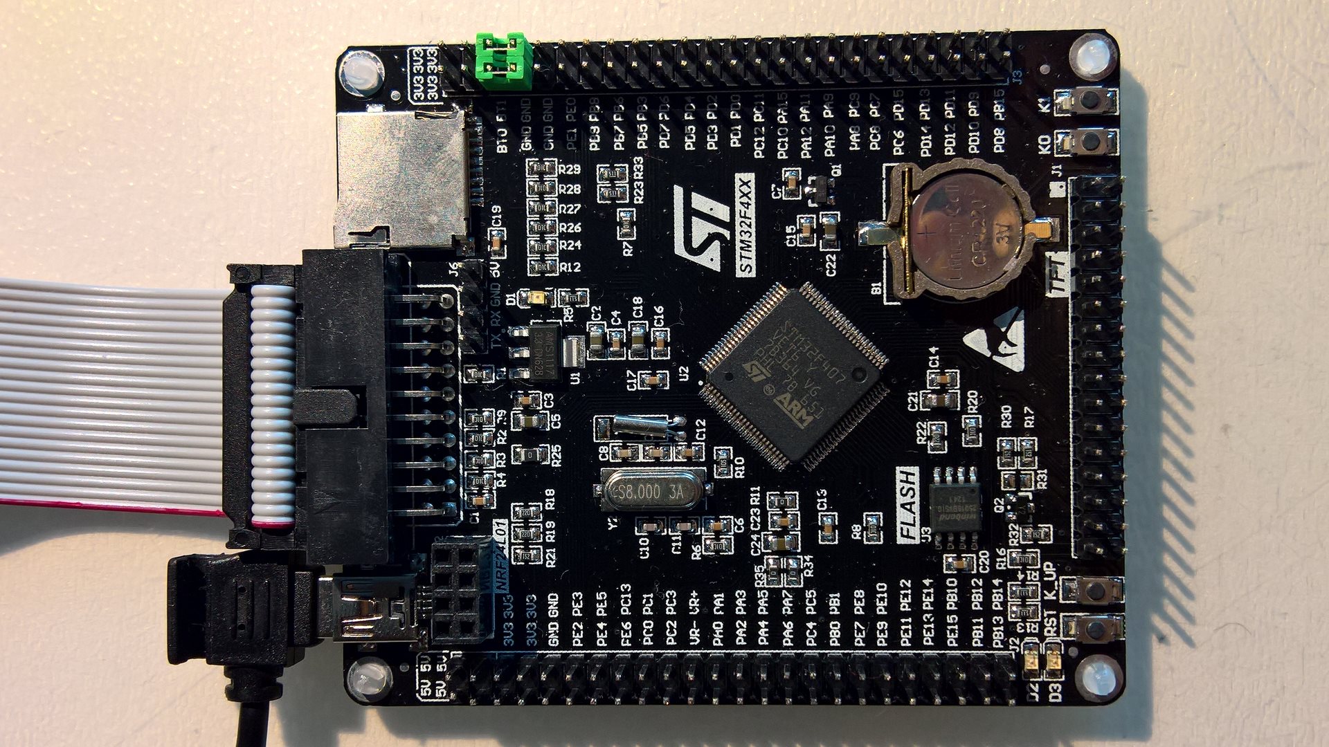
Last friday I also got the 407, so I decided to do a generic one on the weekend: https://github.com/danieleff/STM32GENERIC
Edit: documentation: https://danieleff.github.io/STM32GENERIC/
* Highlight is that USB Serial was working on 103s, on the 407VE, and on L0538-disco (did not test other boards), using the same code.
* tools and a few generic files shamelessly copied from stm32duino
* HAL from STM32 for every series, selecting the right one is with simple ifdefs. Blink should compile on every chip now.
* The implementation as of now is only a light wrapper on HAL (not code from the official core)
* Make it work first (with HAL), make it fast/small later (with register access on a case by case basis)
* Edit: No SPI / I2C / ADC / PWM yet… Although Serial UART is, and based on it, if the API is mostly the same for every series (I think yes), they should not be hard. these are in testable state
* No precompiled-staticlibrary stuff thingy
* Make variants (folder) as light as possible, so a new one can be easily added. Clock setup and pin list and thats it (and unfotunately ldscript). The chip-related peripheral settings are not in variant. (But variant should be able to override defaults.)
* Generated the chip related peripheral setup from cubemx .xml files
* Did not yet rearrange the pins
* Make a script to compile blink & others to see if everything compiles on every variant.
Well I have to go to work now…
Added basic SPI implementation. Official adafruit ili9341 graphicstest already runs happily on black f407
i couldn’t resist trying it !
so the full list of minor tickles
- 1.
chmod u+x /home/stephen/sketchbook/hardware/STM32GENERIC/tools/linux/stlink_upload

chmod u+x /home/stephen/sketchbook/hardware/STM32GENERIC/tools/linux/stlink/st-flash
The HardwareTest library should work now (no need to copy anywhere), there is a loop-back self test.
Connect PA0-PA1, PA6-PA7 (MOSI1-MISO1), RX/TX(UART1), PA2/PA3(UART2).
It tests if sending something on one pin (using digitalwrite/spi write/serial write) is received on the other. Good enough self test.
4 fast blink means a test passes, slow means fails. Later will add more.
Result is also printed through SerialUSB (on Black 407 at least).
Biggest problem is I don’t have enough boards to test with.
Now onto analogread, than analogwrite…
it pretty much matches the schematic, lot of alternates to be set up, but the HAL generated code does that.
i suspect that if the JTAG is reduced to only SWD pins, then PB3 is then free to use as digital, consequently SCK
stephen
Next up: documentation and automated tests.
I’m trying to understand the structure here. So actual implementation is based on CMSIS and HAL libraries which basically covers every peripheral for every board series. For getting this work in Arduino API – a light wrapper has to be created?
“Generated the chip related peripheral setup from cubemx .xml files”. Can I ask how have you done this? is it so that CMSIS/HAL does not contain any chip related peripheral setup code and this needs to be done with e.g. cubemx ? Thanks.
I have written now about the current project structure here: https://danieleff.github.io/STM32GENERI … -structure
Currently lot of things just work by calling the HAL functions.
michael_l wrote: “Generated the chip related peripheral setup from cubemx .xml files”. Can I ask how have you done this? is it so that CMSIS/HAL does not contain any chip related peripheral setup code and this needs to be done with e.g. cubemx ? Thanks.
It’s funny, I’m currently do a similar work to have only one repo for STM32 boards (currently F0/F4 ok. F3/L4/L0 on going) ![]()
Nice work indeed.
FYI, you could use the Arduino CMSIS package (4.5.0) instead of having CMSIS in your repo.
Yes I think it is best to have only one repo for every chip.
For example I just added and tested on F746, and analogread/write, Serial, SPI seems to be working fine with the same codebase.
The biggest problem is the arduino included 4.8.3 arm compiler does not know what ‘-mcpu=cortex-m7’ is… So could only test from Eclipse.
Might have to create a boards manager package for it.
Yes, that board has some interesting chips like 24-bit DAC, microphone accelerometer. Tried also to search code for that accelerometer but couldn’t find. If it uses (didn’t check yet) SPI it must be quite simple. I would believe code and specs is there somewhere in ST.com site just have to find it.
What would be cool is to have USB MSC working and “mount SD card” underneath it so its available for user to browse files
I added preliminary SDIO, and an example to list, read, write files using the Black F407 SD onboard connector with SdFat-beta.
It needs a sdfat-beta config file change (because BlockDriver is typedefed based on a macro. I dont understand why it is not a template parameter), and lot of things not yet implemented (card size, manufacturer, …), however it is testable.
Definitely generic as I2C and Flash pads are empty
The actual silk screen has some nice white dots and text on the underside for each, LED0 / LED1 / KEY1 / KEY2 etc
Hope of interest/use
Stephen
C:\Users\michael\Documents\Arduino\hardware\STM32GENERIC/tools/win/stlink_upload.bat COM17 {upload.altID} {upload.usbID} C:\Users\michael\AppData\Local\Temp\arduino_build_480449/Blink.ino.bin

'stlink\ST-LINK_CLI.exe' is not recognized as an internal or external command,

operable program or batch file.
Oops forgot to say
Linux Debian Jessie 8.x Lenovo Y50 I7 16Gb
</EDIT>
Serial port is identified as MapleMini F103CB
Repo as 0830 this morning.
Black F407VE USB Virtual
Serial Comms Automatic
USB Virtual Com
STLink Automatic SerialUSB
stephen
Request: Could you add FreeRTOS 8.2.1 and/or 9.0 the same it is for BluePill ? Thanks.
Unfortunately the same USB vendor/product ID is used when compiling, and I cannot create a USB product ID for every variant. So for now Serial port will be MapleMini F103CB. I might just remove it.
For that STM32F407ZGT, for now you can just try if the code for 407VE works on it.
Added FreeRTOS (9.0), and there is example for blinking 2 leds. Can you try it?
I’m thinking about to contribute a little bit to your repository.
IMHO it is probably the best to have very simple examples that the people can easily test all peripherals of a board in a few minutes:
https://github.com/ChrisMicro/STM32GENE … nk_allLeds
@michael_l do you mean to use USB and UART? You can use `SerialUSB.print(“…”)`, `SerialUART1.print(“…”)`, `SerialUART2.print(“…”)` to use the specific one.
@michael_l do you mean to use USB and UART? You can use `SerialUSB.print(“…”)`, `SerialUART1.print(“…”)`, `SerialUART2.print(“…”)` to use the specific one.
no keyword hi-lighting with SerialUART1, does compile/run, no output on Serial1(UART1) FTDI usb block
Serial1 is hi-lighted, but Serial1 not declared error message
noticed yesterday, that the first error message is not necessarily the first occurrence of the error in the sketch
blah good code
1st line with error
blah more good code
2nd line with same error
ide stops with error message
also first time into IDE and first upload using stlink, leds flash etc
second upload requires a reset to run it
is that just me or is it the ‘normal’ behaviour?
am i correct in thinking only the HAL generated sys & RCC initialisation routines are used ?
any other customisation for the hardware itself then occurs in the variant files, i.e. afio mode switches, I2C1, SPI3 … … to alternate pins
stephen
<EDIT> just tried the flash example, ‘class SPIFlash’ has no member named ‘begin’
exactly which SdFat repo do i need to pull?
</EDIT>
Thanks, you are quite fast.
I added another example for the user button.
For the on board MEMS accelerometer I need the SPI on pins PA5,PA6,PA7. Can you post me 3 lines of code how to get the SPI on this pins?
If it is not possible, I have to use a software SPI.
Thanks, you are quite fast.
I added another example for the user button.
For the on board MEMS accelerometer I need the SPI on pins PA5,PA6,PA7. Can you post me 3 lines of code how to get the SPI on this pins?
If it is not possible, I have to use a software SPI.
I though we can be probably compatible to the STM-Core library with the LED-names and but the definitions in “variant.h” like they do. But unfortunately they have pin numbers instead of port names
//On-board LED pin number

#define LED_BUILTIN             18

#define LED_GREEN               LED_BUILTIN

#define LED_BLUE                58

#define LED_RED                 19

#define LED_ORANGE 57Changing USB type without reset: yes, it will be possible, but we don’t have HID yet.
@zmemw16:
Serial1: I will alias Serialx to SerialUartx to be compatible, but… I don’t really like it. In original Arduino MEGA, Serial1 means “second” serial, which would be weird here, because “first” changes (Based on menu). (This is the problem with the libmaple core. Serial1 changes based on upload method… but SerialUART1 is self explanatory)
no output on Serial1(UART1) FTDI: can you check with oscilloscope or something(connect a LED)? It works here.
It is not normal if you have to press reset to work.
Only the clock initialization is needed from CubeMX.
Use this for SDIO example: https://github.com/greiman/SdFat-beta, the SdFat subfolder. Don’t forget to change ENABLE_SDIO_CLASS in the library.
@ChrisMicro:
Do not worry about vid/pid in boards.txt. It is only for showing the name next to COMxx. Which is wrong because we have lots of boards with the same. I will remove them. (BTW you can see come here:http://www.linux-usb.org/usb.ids, search for STMicroelectronics)
Currently all extra HAL can be compiled in if you #include “STM32_HAL.h”. For example that way you can use the SRAM functions from stm32XXxx_hal_sram.c
Just use the names for LEDs: `#define LED_BUILTIN Pxy` that will definitely work.
Create a pull request when you think the STM32F429ZI is in OK state.
Create a pull request when you think the STM32F429ZI is in OK state.
Tnaks, I will do that.
I tried some other thinks in the repo:
– compile the BLINK example for the Discovery F746NG ==>
arm-none-eabi-g++: error: unrecognized argument in option ‘-mcpu=cortex-m7’
– compile the FreeRtos example for the Discovery Discovery F407VG ( with corrected LED ) ==>
Example worked only after randomly pressing multiple times the reset button
i thought that of reset as well.
nope still required.
i see this line, on ide entry stlink automatic is already set from previous ide run.
/home/stephen/sketchbook/hardware/STM32GENERIC/tools/linux/stlink_upload ttyUSB0 {upload.altID} {upload.usbID} /tmp/arduino_build_179110/test_gpio2.ino.bin
Could you try again? If still not working, maybe compile st-flash from source. Will investiage further, it is working on windows, and requires reset on linux.
did Roger increase or decrease that time-out for re-enumeration(??) of the usb interface? it’s the only thing i can think that might affect both ? ? ?
re st-flash, before a re-build, maybe i should copy the tools directory from the main Arduino_STM32 repo?
currently PC0/PD3 are twinkling nicely & SerialUSB is outputting mS on my ZGT.
including SPI & Enrf24 headers and the object invocation
#include <SPI.h>

#include <Enrf24.h>

#define NRF_CE PD8

#define NRF_CS PD9

#define NRF_IRQ PD10
Enrf24 radio(NRF_CE, NRF_CS, NRF_IRQ); // CE, CSN, IRQ pins
Therefore I added an example for SerialUSB.
I placed it in the STM32F407 Discovery examples folder, but I think it is valid for most STM boards.
The question is: how could we unify that?
Examples: I have not though about that much. There is of course the built in examples, so board examples should be for the extra stuff, extra LED, extra button, which pin can be used as analog, how to use onboard peripherals…
Yes SPI should work, but you have to keep in mind there are multiple SPI with multiple alternative pins.
Wire also, try to run I2C scanner on 407 discovery.
__STM32F4__ is not defined. I will have some other macro, so that the different cores can be identified correctly.
You mean the following one which I modified for “SerialUSB”:
// --------------------------------------

// i2c_scanner

//

// Version 1

//    This program (or code that looks like it)

//    can be found in many places.

//

//

// This sketch tests the standard 7-bit addresses

// Devices with higher bit address might not be seen properly.

//

// http://playground.arduino.cc/Main/I2cScanner
#include <Wire.h>
#define SERIALINTERFACE SerialUSB
void setup()
{
Wire.begin();
SERIALINTERFACE.begin(9600);
//while (!SERIALINTERFACE); // Leonardo: wait for serial monitor
while(SERIALINTERFACE.available()==0)
{
SERIALINTERFACE.println("\npess any key to start");
delay(1000);
}
SERIALINTERFACE.println("\nI2C Scanner");
}
void loop()
{
byte error, address;
int nDevices;
SERIALINTERFACE.println("Scanning...");
nDevices = 0;
for (address = 1; address < 127; address++ )
{
// The i2c_scanner uses the return value of
// the Write.endTransmisstion to see if
// a device did acknowledge to the address.
Wire.beginTransmission(address);
Wire.write(0);
error = Wire.endTransmission();
if (error == 0)
{
SERIALINTERFACE.print("I2C device found at address 0x");
if (address < 16)
SERIALINTERFACE.print("0");
SERIALINTERFACE.print(address, HEX);
SERIALINTERFACE.println(" !");
nDevices++;
}
else if (error == 4)
{
SERIALINTERFACE.print("Unknown error at address 0x");
if (address < 16)
SERIALINTERFACE.print("0");
SERIALINTERFACE.println(address, HEX);
}
}
if (nDevices == 0)
SERIALINTERFACE.println("No I2C devices found\n");
else
SERIALINTERFACE.println("done\n");
delay(5000); // wait 5 seconds for next scan
}
(Also, use Code tag, not Quote, the whole forum message will be shorter)
the code I used is directly from the Arduino PlayGround documentation.
First I had to introduce the “wait for key pressed” because somehow the SerialUSB did not show anything in the original version.
Another point is if we close the serial monitor window the next time started it will hang.
Put a `Wire.write(0)` before `error = Wire.endTransmission();`, because HAL will not send anything
Same result: no I2C devices.
Could you try this I2C scanner and confirm that it is working on one of your boards correctly?
Can you post a working I2C scanner? Probably it is the best to put it in the developers folder so anyone can test the I2C interfaces.
This was a very helpful question. Thanks.
There is a audio codec on the board and I read the schematics ( p.39 )
It is necessary to enable the chip first:
#define AUDIOCODEC_CS PD4

pinMode(AUDIOCODEC_CS,OUTPUT);

digitalWrite(AUDIOCODEC_CS,HIGH);
Could you post the result if it is working? Then we can put it in the examples folder. This would help other people allot
BTW: I just pushed the I2C reader to the repo.
Starting test

Beginning Whetstone benchmark at default speed ...

Loops:1000, Iterations:10, Duration:8581.59 millisec

C Converted Single Precision Whetstones:116.53 mflops
- LIS3DSH_demo.ino
- LIS3DSH demo
- (1.9 KiB) Downloaded 28 times
I’m one minute to slow ![]()
I have added a simple accelerometer example using the SPI interface. ![]()
Do you have any funny application idea?
I’m one minute to slow ![]()
I have added a simple accelerometer example using the SPI interface. ![]()
Do you have any funny application idea?
Starting test

Beginning Whetstone benchmark at default speed ...

Loops:1000, Iterations:10, Duration:8581.59 millisec

C Converted Single Precision Whetstones:116.53 mflops
I’m one minute to slow ![]()
I have added a simple accelerometer example using the SPI interface. ![]()
Do you have any funny application idea?
That is a good idea. So it would be an application example which does not need the serial interface which could be good for a quick test.
We have made almost the same code. But there are some little differences:
You use SPI_MODE0. I found somewhere a code with SPI_MODE3 and didn’t investigate if it is right. It works but it could be accidental. Which one is the correct setup?
How do you connect the serial port? On my board only the SerialUSB seems to work. Or do you use an external USB adapter?
Later on I would include your sketch also in the examples folder because it can use the serial plotter.
BTW.: I think your coding style is very good, short and readable ![]()
It looks very promising if it is really that easy to add new board as Daniel intended.
Few months ago there wasn’t a really good F4 core, and now it’s difficult to choose what to use
Yes, it works quite easy to add a new board. I added a STM32F429 Discovery and I will probably add more.
The problem with the discovery boards is that they have a lot of peripheral where there are no examples at the moment.
So I try to make some examples to enable the people to use this boards easily.
Yesterday I tried to implement a sound example for the on board codec CS43L22 on the STM32F4 discovery. But I didn’t succeed.
The I2S is not implemented in the core and the HAL-examples do not compile. It seems as if the dedicated STM32F4xx files are missing.
#include "I2S.h"

I2SClass i2s(SPI3, PC12 /*sd*/ , PA4 /*ws*/, PC10 /*ck*/); // check board schematic

...

i2s.begin(I2S_PHILIPS_MODE, 44000, 16);

i2s.write(data);Edit: Sloeber issue solved – issue with indexing the sources..
Variant Black ZE attached.
And a single FFT (fpu) while sampling w/ about 500Hz at PA3 while touching the pin with my finger (my fingerprint)
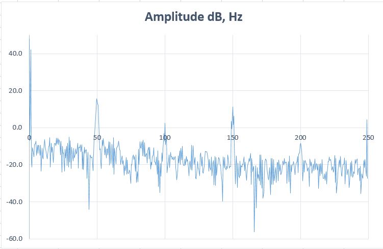
- DE407 core FFT 1024 Hanning and 500Hz sampling.JPG (32.35 KiB) Viewed 337 times
Again, absolutely untested
Very good, I will see if it is working
and you need to set up first the CS43L22 using I2C anyway (It has a beep mode I think so that should be first to try)
The main problem is the CS43L22 needs MCLK of around 12MHz from the STM32F407. Does the I2S driver provide that?
And the FFT (fpu) while sampling w/ about 500Hz at PA3 while touching the pin with my finger (my fingerprint) ![]()
Very nice. Why did you choose only 500Hz ?
For a serious work we need to have the ADC sampling based on a TimerX trigger and push the ADC data via DMA to FFT.
Basically everything has been done in chibios already, as I wrote somewhere.
So it could be a good source of inspiration when using the STM HAL..
That is a good idea. So it would be an application example which does not need the serial interface which could be good for a quick test.
We have made almost the same code. But there are some little differences:
You use SPI_MODE0. I found somewhere a code with SPI_MODE3 and didn’t investigate if it is right. It works but it could be accidental. Which one is the correct setup?
How do you connect the serial port? On my board only the SerialUSB seems to work. Or do you use an external USB adapter?
Later on I would include your sketch also in the examples folder because it can use the serial plotter.
BTW.: I think your coding style is very good, short and readable ![]()
That would require SdFat via SPI or SDIO..
I think you could do an MP3 too, at least an MP3 player with DiscoF407 worked fine.. http://www.chibios.com/forum/viewtopic.php?f=8&t=351
Ahh … this would mean that Serial.begin() is the same as SerialUSB.begin() ? I thought “Serial” goes to PA8,9 and could be soldered to the on board ST-Link. There was something written in the manual .. but on my computer never a virtual com port appeared when I connected the board. The SerialUSB sometimes hangs on my computer …
Thanks, that sketch was made quite quickly and could be enhanced a bit but maybe it would be worth to create an Arduino library for LIB3DSH?
That would be a very good step after we can access all peripherals with simple example sketches.
The simple basic examples should be kept because libraries tend to grow after a certain time because the people want more and more features. Then it is good to still have the very basic examples accessible to see how the basic things works.
However I’d be more interested to get ST MEMS microphone (MP45DT02) working. I’m not sure but I think it must also use I2S. Should we try to tinker with that next ? It would be kind of cool to create a program that uses microphone to save sound and output it via the on board DAC ![]()
I experimented a little bit with the microphone. Here is a bit banging code for a VU-meter which shows the noise level with the LEDs. Unfortunately it did only work with the LibMaple Core from Roger. I think the generic core has a different timing. The microphone could also used analog. In the board manual it is described. But to solder a bridge on the board is necessary and the microphone hast to be provided with a clock. Do you know how to generate about 3MHz? To use the microphone digitally some digital filters are required which means some processing overhead. There is a application note from STM about it. Probably even some code from STM could be found somewhere.
// LED VU-Meter

// turns on the LEDs depending on the sound level detected from the microphon

// STM32F4 Discovery
#define USERBUTTON PA0
#define GREENLED PD12
#define ORANGELED PD13
#define GREDLED PD14
#define BLUELED PD15
#define REDLEDOTGOVERCURRENT PD5
#define MICROPHON_CLK_INPUT PB10
#define MICROPHON_PDMDATA_OUTPUT PC3
#define NUMLEDS 5
const uint8_t Led[] = {GREENLED, ORANGELED, GREDLED, BLUELED, REDLEDOTGOVERCURRENT};
void setup()
{
for (int n = 0; n < NUMLEDS; n++) pinMode(Led[n], OUTPUT);
pinMode(MICROPHON_CLK_INPUT, OUTPUT);
}
void setLed(uint8_t n, uint8_t state)
{
if(n==4)digitalWrite(Led[n], !state);
else digitalWrite(Led[n], state);
}
#define SAMPLEBUFFERLENGTH 400
int16_t sampleBuffer[SAMPLEBUFFERLENGTH];
int32_t OldValue = 0;
void sampleMicrophon()
{
int32_t n, k;
int32_t sample = 0;
for (n = 0; n < SAMPLEBUFFERLENGTH; n++)
{
int32_t value = 0;
for (k = 0; k < 500; k++)
{
digitalWrite(MICROPHON_CLK_INPUT, HIGH);
if (digitalRead(MICROPHON_PDMDATA_OUTPUT) == 0) value--;
else value++;
digitalWrite(MICROPHON_CLK_INPUT, LOW);
}
sample = value - OldValue;
OldValue = value;
sampleBuffer[n] = sample;
}
sampleBuffer[0] = 0;
sampleBuffer[1] = 0;
}
double calcPower()
{
double power=0;
int32_t n;
for (n = 0; n < SAMPLEBUFFERLENGTH; n++)
{
power+=(double)sampleBuffer[n]*sampleBuffer[n];
}
return power=power/SAMPLEBUFFERLENGTH;
}
void loop()
{
sampleMicrophon();
double power=calcPower();
if(power>80) setLed(0,1);
else setLed(0,0);
if(power>100) setLed(1,1);
else setLed(1,0);
if(power>200) setLed(2,1);
else setLed(2,0);
if(power>400) setLed(3,1);
else setLed(3,0);
if(power>800) setLed(4,1);
else setLed(4,0);
}
Is that intentional? If not, I believe it would be better to add it for compatibility, as provides a common way to know the target speed across boards and platforms.
That would require SdFat via SPI or SDIO..
I think you could do an MP3 too, at least an MP3 player with DiscoF407 worked fine.. http://www.chibios.com/forum/viewtopic.php?f=8&t=351
There is a Arduino Sound Library which unfortunately is only made for the Arduino Zero. But it show a simple a simple to use architecture.
The best would be to have the same for STM32.
Type any character to start

Type is FAT32

Card size: 8.03 GB (GB = 1E9 bytes)
Manufacturer ID: 0X1B

OEM ID: SM

Product: 00000

Version: 1.0

Serial number: 0X5D7445A7

Manufacturing date: 1/2015
File size 5 MB

Buffer size 8192 bytes

Starting write test, please wait.
write speed and latency

speed,max,min,avg

KB/Sec,usec,usec,usec

1541.37,65992,4222,5308

1630.91,14885,4218,5016

1621.39,19496,4218,5045

1630.38,14924,4222,5018

1625.08,14948,4223,5034

1623.50,14948,4222,5040
Starting read test, please wait.
read speed and latency

speed,max,min,avg

KB/Sec,usec,usec,usec

1864.60,6197,4355,4392

1865.99,5247,4353,4389

1866.69,5246,3359,4386

1865.99,5247,4354,4389

1866.69,5249,4353,4388

1865.99,5248,4352,4389
Done
I added yesterday an I2S, HOWEVER I do not have hardware for that so no way to try.
Your I2S implementation works. Congratulation ![]()
I just tried it on the STM32F407 board with an Adafruit I2S amplifier instead of the on board codec.
It produces a loud sawtooth sound ( sawtooth for code simplicity ):
#include "I2S.h"
I2SClass I2S(SPI3, PC12 /*sd*/ , PA4 /*ws*/, PC10 /*ck*/); // check board schematic
void setup()
{
I2S.begin(I2S_PHILIPS_MODE, 44000, 16);
}
void loop()
{
static uint16_t n;
I2S.write(n+=300);
}
Hmm, but 84/42 div by 12 is not an integer..
Change the cpu freq to 192.. 96/12=8
so that each issue can be discussed in separate thread.
as the attached hardware is the same circuit, i wondered why ?
stephen
Postby Pito
There are 2 timer’s channels on the PC7 – it could be done with Timers.. CaptureCompareRegs..
Hmm, but 84/42 div by 12 is not an integer..
Change the cpu freq to 192.. 96/12=8
Thank you for the answer. My question seems for every one so simple and no one wants to give an answer. ![]()
What I need is a code example … or a hint how to
so that each issue can be discussed in separate thread.
Postby Pito
There are 2 timer’s channels on the PC7 – it could be done with Timers.. CaptureCompareRegs..
Hmm, but 84/42 div by 12 is not an integer..
Change the cpu freq to 192.. 96/12=8
Thank you for the answer. My question seems for every one so simple and no one wants to give an answer. ![]()
What I need is a code example … or a hint how to
The naumber is always the same 4294966553, it seems.
The source says it measures maxLatency via micros(), it compares and does simple addition. All uints.
Then it prints out the stuff:
cout << s/t <<',' << maxLatency << ',' << minLatency;The source says it measures maxLatency via micros(), it compares and does simple addition. All uints.
Then it prints out the stuff:
cout << s/t <<',' << maxLatency << ',' << minLatency;It comes about 5x per hundred results, it seems randomly.. Sometimes like
1964.51,4294966553,256,257

1844.90,4294966553,256,258

1960.66,1334,256,258

1953.00,1331,256,258This is how STM implemented it in their core(micros () is just return GetCurrentMicro;)
uint32_t GetCurrentMicro(void)

{

return (HAL_GetTick()*1000) + (SysTick->VAL / (SystemCoreClock / 1000000));

}
in addition, i’d suggest that threads there referencing this core prefix with STM32GENERIC, but it’d need a little co-operation from all so that it is easier to identify the subjects.
![]()
i’ve reverted to the 260417-1230’ish repo, i will explore the latest again later.
did someone say they had the i2cscanner running ?
Unknown error at address
On my setup Win10, STM32F4 Discovery from my repo it is working. I just tried it again.
What board do you use?
I just tried it, but the serial displays only constant values and the LEDs are not changing ![]()
Did you take a look at the Blink_allLeds Example? All the LEDs are defined in “variant.h”
You can access them by colors: LED_GREEN, LED_ORANGE, LED_RED, LED_BLUE
handle.Init.MCLKOutput = I2S_MCLKOUTPUT_DISABLE;
and missing pin here:
I2SClass::I2SClass(SPI_TypeDef *instance, uint8_t sd, uint8_t ws, uint8_t ck) {
handle.Instance = instance;
this->sdPort = variant_pin_list[sd].port;
this->sdPin = variant_pin_list[sd].pin_mask;
this->wsPort = variant_pin_list[ws].port;
this->wsPin = variant_pin_list[ws].pin_mask;
this->ckPort = variant_pin_list[ck].port;
this->ckPin = variant_pin_list[ck].pin_mask;
// !!!!! no MCCLK pin !!!!!
}
i’ll add ssd1306 display to the setup post sleep time
stephen
The Example in the Discovery F407VG folder is made for the STM32F4 Discovery board.
This mainly means that sets the chip select lines for the I2C devices on that board.
You could select the Discovery Board in your IDE and see if the scanner works. ( Be sure that the select line is not colliding with some of your hardware ).
You will find it in the examples folder.
Daniel: special thanks to you for your great support with the I2S driver ![]()
Michael: how is your microphone driver proceeding?
You will find it in the examples folder.
Daniel: special thanks to you for your great support with the I2S driver ![]()
Michael: how is your microphone driver proceeding?
Strange … Does it have something to do with the SPI-mode seutp? Or probably the SerialUSB?
In my code I placed the wait for char from serial to improve the behaviour a little bit.
BTW.:
shall we move to the STM32F4 Discovery thread because the STM32GENERIC is meant for all boards ?
Actually it was the definition of INPUT_ANALOG that was missing…. I thought I’d test compile my main project against GENERIC to see what was broken, and the following fails:
  for (int x = 7; x < 11; x++) {

pinMode(x, INPUT_ANALOG);

}
Many of them like analogReadSerial should also work on other boards, when you adapt the pin setting.
It helps to avoid problems like the one before you had with pinMode(xx,ANALOG_INPUT) because it is described in the example.
Many of them like analogReadSerial should also work on other boards, when you adapt the pin setting.
It helps to avoid problems like the one before you had with pinMode(xx,ANALOG_INPUT) because it is described in the example.
A) select SerialUART in menu, then write Serial.begin(…); Serial.print(…)
or
B) Use SerialUARTx.begin(…); SerialUARTx.print(…)
Could you try all SerialUART1, SerialUART2…?
@michael_l: Currently if you #include “STM32_HAL.h” in Arduino then all the HAL extra stuff should be compiled. (except SPI/I2C, for those include as usual).
Tried TX
SerialUART1 ok, 115k2
SerialUART1 + SerialUART2 ok, both 115k2
SerialUART1 + SerialUART3 ok, both 115k2
Here is the basic low level code for sending on UART2, PA2/PA3, just generated with CubeMX, if for some the SerialUARx does not work, could you try this:
void setup() {

__HAL_RCC_USART2_CLK_ENABLE();

__HAL_RCC_GPIOA_CLK_ENABLE();
GPIO_InitTypeDef GPIO_InitStruct;
GPIO_InitStruct.Pin = GPIO_PIN_2|GPIO_PIN_3;
GPIO_InitStruct.Mode = GPIO_MODE_AF_PP;
GPIO_InitStruct.Pull = GPIO_PULLUP;
GPIO_InitStruct.Speed = GPIO_SPEED_FREQ_VERY_HIGH;
GPIO_InitStruct.Alternate = GPIO_AF7_USART2;
HAL_GPIO_Init(GPIOA, &GPIO_InitStruct);
UART_HandleTypeDef handle;
handle.Instance = USART2;
handle.Init.BaudRate = 115200;
handle.Init.WordLength = UART_WORDLENGTH_8B;
handle.Init.StopBits = UART_STOPBITS_1;
handle.Init.Parity = UART_PARITY_NONE;
handle.Init.Mode = UART_MODE_TX_RX;
handle.Init.HwFlowCtl = UART_HWCONTROL_NONE;
handle.Init.OverSampling = UART_OVERSAMPLING_16;
HAL_UART_Init(&handle);
while(1) {
char data[] = "Hello!\n";
HAL_UART_Transmit(&handle, (uint8_t*)data, sizeof(data) - 1, 1000 /*timeout*/);
delay(500);
}
}
stephen

- F4Disco Uart1 PA9 PA10.JPG (60.05 KiB) Viewed 398 times
@zmemw16 I do not have all the boards, and time to go through every schematic. Currently all UARTs should be usable, on defaulted to the primary pin (the same CubeMX gives first if you enable). You can set alternate pins with SerialUARTx.stm32SetRX(…). The variants will be able to change defaults when it is implemented (Some #define in variant.h, do not know what to name them…).
If the low level code also gives garbage, than it is a baud mismatch, possibly clock setup error, the board does not have the 8Mhz crystal, uses something else, or some other problem.
// --------------------USART--------------------
const stm32_af_pin_list_type chip_af_usart_rx [] = {

//USART1

{ USART1, GPIOA, GPIO_PIN_10 , GPIO_AF7_USART1},

{ USART1, GPIOB, GPIO_PIN_7  , GPIO_AF7_USART1},

//USART2

{ USART2, GPIOA, GPIO_PIN_3  , GPIO_AF7_USART2},

{ USART2, GPIOD, GPIO_PIN_6  , GPIO_AF7_USART2},

//USART3

{ USART3, GPIOB, GPIO_PIN_11 , GPIO_AF7_USART3},

{ USART3, GPIOC, GPIO_PIN_11 , GPIO_AF7_USART3},

{ USART3, GPIOD, GPIO_PIN_9  , GPIO_AF7_USART3},

//USART6

{ USART6, GPIOC, GPIO_PIN_7  , GPIO_AF8_USART6},

{ USART6, GPIOG, GPIO_PIN_9  , GPIO_AF8_USART6},

};
const stm32_af_pin_list_type chip_af_usart_tx [] = {

//USART1

{ USART1, GPIOA, GPIO_PIN_9  , GPIO_AF7_USART1},

{ USART1, GPIOB, GPIO_PIN_6  , GPIO_AF7_USART1},

//USART2

{ USART2, GPIOA, GPIO_PIN_2  , GPIO_AF7_USART2},

{ USART2, GPIOD, GPIO_PIN_5  , GPIO_AF7_USART2},

//USART3

{ USART3, GPIOB, GPIO_PIN_10 , GPIO_AF7_USART3},

{ USART3, GPIOC, GPIO_PIN_10 , GPIO_AF7_USART3},

{ USART3, GPIOD, GPIO_PIN_8  , GPIO_AF7_USART3},

//USART6

{ USART6, GPIOC, GPIO_PIN_6  , GPIO_AF8_USART6},

{ USART6, GPIOG, GPIO_PIN_14 , GPIO_AF8_USART6},

};
@zmemw16 I do not have all the boards, and time to go through every schematic. Currently all UARTs should be usable, on defaulted to the primary pin (the same CubeMX gives first if you enable). You can set alternate pins with SerialUARTx.stm32SetRX(…). The variants will be able to change defaults when it is implemented (Some #define in variant.h, do not know what to name them…).
If the low level code also gives garbage, than it is a baud mismatch, possibly clock setup error, the board does not have the 8Mhz crystal, uses something else, or some other problem.
Daniel’s “low level” code works
SerialUART1 does not work (garbage output)
SerialUART2 works !
So something has been “off” yesterday on my computer. I believe my FTDI chip has some problems (there’s no other explanation)
Either remapping pins for UART1 or disabling UART1 are the reasonable options
Daniel’s “low level” code works
SerialUART1 does not work (garbage output)
SerialUART2 works !
So something has been “off” yesterday on my computer. I believe my FTDI chip has some problems (there’s no other explanation)
Either remapping pins for UART1 or disabling UART1 are the reasonable options
Daniel’s “low level” code works
SerialUART1 does not work (garbage output)
SerialUART2 works !
So something has been “off” yesterday on my computer. I believe my FTDI chip has some problems (there’s no other explanation)
Either remapping pins for UART1 or disabling UART1 are the reasonable options
  	if (!static_rx_used) {

txBuffer = (uint8_t*)rx;     <<<< shall be rxBuffer

static_rx_used = true;

} else {

rxBuffer = (uint8_t*)malloc(BUFFER_SIZE);

}

}
  	if (!static_rx_used) {

txBuffer = (uint8_t*)rx;     <<<< shall be rxBuffer

static_rx_used = true;

} else {

rxBuffer = (uint8_t*)malloc(BUFFER_SIZE);

}

}
The dma based BluePill does 3.5MB/sec rd/wr @36MHz, we currently do a half on F407.
And then there is a file SdioTeensy.cpp with SDIO enabled for F4 something.. Freescale or NXP or how it is called today..
Bill claims 20MB/sec on SDIO Teensy @240MHz..
@Daniel: it seems we need an extra flag __STM32F4__ to add into extra.flag=.. as the SdFat uses that type..
PS: The SdFat repo has been refreshed yesterday, so download the latest version, I think the -beta is in.
There is a minimum SDIO, and SdFat-beta with SDIO in BoardExamples / Black 407VE
The dma based BluePill does 3.5MB/sec rd/wr @36MHz, we currently do a half on F407.
And then there is a file SdioTeensy.cpp with SDIO enabled for F4 something.
SdFat with SDIO is working already?
We could also make it work so that part of the flash memory is used for the filesystem. Then it could work also on boards without extra chip.
“general” Spi dma would be nice because there are many spi devices at the moment so all could benefit from it.
I’m also interested in CAN driver. There seems to be quite many HAL based implementation’s on the net and one in phonog’s repo for F103 that has arduino api but internally implemented with libmaple.
Is there DMA channel for CAN available? ![]()
Pito: Check the examples folder I think I saw something there.
http://www.st.com/content/ccc/resource/ … 037591.pdf
We could also make it work so that part of the flash memory is used for the filesystem. Then it could work also on boards without extra chip.
“general” Spi dma would be nice because there are many spi devices at the moment so all could benefit from it.
I’m also interested in CAN driver. There seems to be quite many HAL based implementation’s on the net and one in phonog’s repo for F103 that has arduino api but internally implemented with libmaple.
Is there DMA channel for CAN available? ![]()
Pito: Check the examples folder I think I saw something there.
From this thread I learned about the naming of the serial ports so I added an example. I hope my understanding of the things is correct and the description in the example also. If you have any hints ( or you are a native English speaker ) feel free to extend or correct the example.
@Daniel: I apologize not directly have answered to you request. Is it all solved with the serial ports now?
Do you have a board with included ST-Link V2.1 (Not just V2)? You could also try the ST-Link virtual COM too there.
I try to diminish for all people the confusion by providing the examples.
And also important: the description in the examples header.
I have a serial to USB converter. I think there is no problem.
My main attempt is to provide the people easy an access to the STM Arduino because if it is easier to use, more people will use it and more software is contributed.
Sometimes the SerialUSB hangs on my STM32F4 Discovery connected to WIN10 over a USB-Hub.
But I could decrease this hanging by adding a wait for serial char at the beginning of the program to prevent the board sending right from the start.
You can see this in some examples.
I think Arduino is useful when “one click examples” are working. This means: Click on the example, it compiles, flashes and runs.
Another really useful advantage of short examples is, that they can be used as templates: Simply copy and paste. Therefore examples shall be short and clear ( I’m not sure if I reach still goal every time ).
I put the HAL example from Michael into the repo.
Because there is no DAC driver in the STM32GENERIC I thought I could simply generate one with STMCubeMX and then simply copy parts of it.
But that didn’t work because of a lot missing dependencies.
So: How do you usually generate the HAL examples ?
In the schematic it seems that USB ist connected to PA11/12
In the schematic it seems that USB ist connected to PA11/12
I’m sure he was doing this because he wrote “it works no every time”.
On my STM32F4 Discovery I have the same: It woks not every time, some times the whole serial monitor in the IDE hangs.
@ChrisMicro: There are 2 types of problems I encountered (given USB is enumerated):
- If I upload a new sketch, the serial monitor needs to be closed / reopened. Can I get a confirmation on this? This probably can not be fixed unless we modify Arduino IDE the way teensy does like here and here. Probably not going to happen.
- If I send too much data, it hangs and cannot even close the serial monitor. Can only fix by unplugging USB (or reseting the board). I “think” I had success fixing this by setting CDC_SERIAL_BUFFER_SIZE to 4K in STM32/cores/arduino/usb/usbd_cdc_if.h
If I upload a new sketch, the serial monitor needs to be closed / reopened. Can I get a confirmation on this? This probably can not be fixed unless we modify Arduino IDE the way teensy does like here and here. Probably not going to happen.
I flash the “Serial_portUsage.ino” example for the test.
STM32F4 Discovery, Win10, Arduino IDE 1.8.0 : After downloading I open the serial Monitor. It runs without problems.
If I let the serial monitor open and try to flash, I get
processing.app.SerialException: Error opening serial port ‘COM5’.
But that is normal.
So with this test scenario I would say every thing works as it should.
Test with “Serial_boardUsage.ino” example again. But with delay time decreased to delay(1) instead of delay(1000).
I open and close the serial monitor window repetitive.
After the third attempt the IDE hangs.
Plan to soon add support for the FSMC ?
Plan to soon add support for the FSMC ?
Plan to soon add support for the FSMC ?
Just found Daniel had sent a bunch of commits, and merging them solved the problems I was having with F1.
I have updated my SPI-DMA branch to support spi dma in F1 series, still untested .If anyone test it, please let me know.
I Also just realized platformio doesn’t work for STM32GENERIC like it works for stm32duino. That would be nice to get working also. I wonder if anyone has ready make “template” or importable project for basic STM32GENERIC .ino project for Eclipse ? Thanks.
STM32DE\cores\arduino\stm32\stm32_gpio_af.c:59:17: error: 'chip_af_i2s_sd' undeclared (first use in this function)

stm32AfInit(chip_af_i2s_sd, sizeof(chip_af_i2s_sd) / sizeof(chip_af_i2s_sd[0]), instance, sdPort, sdPin, GPIO_MODE_AF_PP, GPIO_NOPULL);

..Any reason to use __STM32F1__ instead of STM32F1?
I cope with other issue however
I cannot upload via DFU into my MapleM (DFU bootloader 0x2000). It does not wait a single second and jumps to STLink..
Starting upload

using arduino loader

Starting reset using DTR toggle process

Toggling DTR

Continuing to useCOM18

Ending reset

..

..tools/win/stlink_upload.bat COM18 2 1EAF:0003 C:\Users\pito\MyCode\Sloeber\SDBench/Release/SDBench.bin

Output:

STM32 ST-LINK CLI v2.1.0

STM32 ST-LINK Command Line Interface

No ST-LINK detected!Can you try it? And project/properties/arduino/apply.
That is not enough it seems..
I’ve changed in platform.txt:
# Upload using Maple bootloader over DFU

tools.maple_upload.cmd=maple_upload

tools.maple_upload.cmd.windows=maple_upload.bat

#tools.maple_upload.path={runtime.tools.STM32Tools.path}/tools/win

tools.maple_upload.path.windows={runtime.hardware.path}/tools/win             <<<<<<<<<<<<<<<< My path
I just tried again to compile for the STM32F746 Discovery
The result still
arm-none-eabi-g++: error: unrecognized argument in option ‘-mcpu=cortex-m7’
the compiler call ( where you can see the version ) is
…\AppData\Local\Arduino15\packages\STM32\tools\arm-none-eabi-gcc\4.8.3-2014q1/bin/arm-none-eabi-g++” -mcpu=cortex-m7 …
I think following the installation description in your repository I do not get a compiler witch supports the F7
Where did you get the right compiler?
Install, then manually change STM32/platform.txt `compiler.path=` to point to your version.
I hope I will be able to package it with the boards manager package. Until then this is the only way… (I could put it into repo, but its like few 100GB, so rather not)
Edit: Actually anybody knows the difference between https://launchpad.net/gcc-arm-embedded (5-2016-q3) and https://developer.arm.com/open-source/g … /downloads (6-2017-q1)?
i’m using that from arm’s web site
Here is another topic:
Because compiling the “Blink Example” for my Nucleo L476RG did not work, I tested to compile the Blink for all Nucleo boards supported by STM32GENERIC.
Nucleo F030R8 ==> ERROR
C:\Tools\Arduino\Arduino1_8\hardware\STM32GENERIC\STM32\cores\arduino\stm32\stm32_PWM.c: In function ‘analogWrite’:
C:\Tools\Arduino\Arduino1_8\hardware\STM32GENERIC\STM32\cores\arduino\stm32\stm32_PWM.c:37:30: error: ‘TIM2_IRQn’ undeclared (first use in this function)
HAL_NVIC_SetPriority(TIM2_IRQn, 0, 0);
Nucleo F103RP ==> OK
Nucleo F303RE ==> OK
Nucleo F411RE ==> OK
Nucleo L053R8 ==> OK
Nucleo L152RE ==> OK
Nucleo L476RG ==> ERROR
Sketch too big; see http://www.arduino.cc/en/Guide/Troubleshooting#size for tips on reducing it.
Error compiling for board Nucleo-64 boards.
It is now compiling and downloading, but not blinking.
If I try to compile the “Serial_portUsage.ino” in the “all_boards” example folder I get:
..\AppData\Local\Temp\arduino_build_88383/core\core.a(stm32XXxx_hal_uart.c.o): In function `HAL_UART_IRQHandler’:
C:\Tools\Arduino\Arduino1_8\hardware\STM32GENERIC\STM32\system/STM32L4/HAL_Src/stm32l4xx_hal_uart.c:1665: undefined reference to `HAL_UARTEx_WakeupCallback’
collect2.exe: error: ld returned 1 exit status
I have the following test results:
– the pre selected upload method “Mass Storage” does not work
+ the ST-Link upload works
+ blink works
+ serial works
– if I disconnect the board and reconnect it, the flashed program does not start. I have to reflash
I hope I will be able to package it with the boards manager package. Until then this is the only way… (I could put it into repo, but its like few 100GB, so rather not)
Edit: Actually anybody knows the difference between https://launchpad.net/gcc-arm-embedded (5-2016-q3) and https://developer.arm.com/open-source/g … /downloads (6-2017-q1)?
Mass storage: When you plug it in, is the new drive name the same as in `.massstorage_drive=NODE_F401RE`?
flashed program does not start: Even simple blink? And pressing reset?
Later I will fix those compile errors.
@fpiSTM: If you create a tools package for it, may I use that too?
flashed program does not start: Even simple blink? And pressing reset?
The drive is there: “NODE_F401RE”
If I look at it with the file explorer, “Blink.ino.bin” is also there. But it does not blink. Even after reset.
If I unplug and plug it again, “Blink.ino.bin” is gone.
Oh, hmm… yes … I thought they are the same except some differences in peripherals and Memory …
Do you have STM32CubeMX?
I have, but I didn’t use it. This is what it produces when I select the Nucleo F401 without any modifications:
void SystemCoreClockUpdate(void)

{

uint32_t tmp = 0, pllvco = 0, pllp = 2, pllsource = 0, pllm = 2;
/* Get SYSCLK source -------------------------------------------------------*/
tmp = RCC->CFGR & RCC_CFGR_SWS;
switch (tmp)
{
case 0x00: /* HSI used as system clock source */
SystemCoreClock = HSI_VALUE;
break;
case 0x04: /* HSE used as system clock source */
SystemCoreClock = HSE_VALUE;
break;
case 0x08: /* PLL used as system clock source */
/* PLL_VCO = (HSE_VALUE or HSI_VALUE / PLL_M) * PLL_N
SYSCLK = PLL_VCO / PLL_P
*/
pllsource = (RCC->PLLCFGR & RCC_PLLCFGR_PLLSRC) >> 22;
pllm = RCC->PLLCFGR & RCC_PLLCFGR_PLLM;
if (pllsource != 0)
{
/* HSE used as PLL clock source */
pllvco = (HSE_VALUE / pllm) * ((RCC->PLLCFGR & RCC_PLLCFGR_PLLN) >> 6);
}
else
{
/* HSI used as PLL clock source */
pllvco = (HSI_VALUE / pllm) * ((RCC->PLLCFGR & RCC_PLLCFGR_PLLN) >> 6);
}
pllp = (((RCC->PLLCFGR & RCC_PLLCFGR_PLLP) >>16) + 1 ) *2;
SystemCoreClock = pllvco/pllp;
break;
default:
SystemCoreClock = HSI_VALUE;
break;
}
/STM32/system/STM32F1/stm32_chip/stm32_STM32F103RF.h:128: undefined reference to `__HAL_AFIO_REMAP_SPI3_ENABLE’
For the NUCLEO_F476RG I have the linker script corrected according to
http://www.openstm32.org/forumthread2359
Now the Board is working as expected. Download via ST-Link and Mass storage works.
For the F401 I have corrected the clock settings copying the ones from STMCube.
The Board behaves as before: Blink runs only after download with ST-Link.
L476RG ah then RAM LENGTH = 128K is wrong also.
I have reduced the ram length now to 96K even if they sell it as 128K.
Both Nucleo 64 boards ( F401RE and L476RG ) are working now as they are expected ( from my side ![]() )
)
The problem of the F401RE with the “mass storage download” was an on-board ST-LINK V2 proplem: I had to update it with the “STM32 ST-LINK Utility” then it was working correct.
So .. if you want .. you can merge.
@michael
Did you try my STM32F4 Discovery examples the microphone is working a little bit …
@michael_l I can add package.json, is there somewhere a documentation of it?
L476RG ah then RAM LENGTH = 128K is wrong also.
@michael_l I can add package.json, is there somewhere a documentation of it?
@michael
Did you try my STM32F4 Discovery examples the microphone is working a little bit …
C:\Users\pito\MyCode\Sloeber\SDBench_F1\Release\arduino.ar(stm32_gpio_af.c.o): In function `AF__HAL_AFIO_REMAP_SPI3_ENABLE':

C:/Users/pito/MyCode/Arduino/hardware/Arduino_STM32SerBuff/STM32DE/system/STM32F1/stm32_chip/stm32_STM32F103ZE.h:250: undefined reference to `__HAL_AFIO_REMAP_SPI3_ENABLE'

C:\Users\pito\MyCode\Sloeber\SDBench_F1\Release\arduino.ar(stm32_gpio_af.c.o): In function `AF__HAL_AFIO_REMAP_SPI3_DISABLE':

C:/Users/pito/MyCode/Arduino/hardware/Arduino_STM32SerBuff/STM32DE/system/STM32F1/stm32_chip/stm32_STM32F103ZE.h:249: undefined reference to `__HAL_AFIO_REMAP_SPI3_DISABLE' while (!Serial.available()) {
}; while (!Serial.available()) {
}; while (!Serial.available()) {
};Can you confirm you can enter data into MMini via SerialUART?
By the way, transmitting works? (both are implemented with interrupt ringbuffer)
The RX does not.. I will try with a demo..
//#define Serial SerialUART1

//#define Serial Serial1
int incomingByte = 0;   // for incoming serial data

void setup() {

Serial.begin(115200);

Serial.println("Serial Demo, enter a char:");

}

void loop() {

if (Serial.available() > 0) {

incomingByte = Serial.read();

Serial.print("I received: ");

Serial.println(incomingByte, HEX);

}

}
This seems ro work fine for me on F1:
SerialUSBClass::operator bool()

{

// this is here to avoid spurious opening after upload

if (millis() < 500)

return false;
bool result = false;

if(hUsbDeviceFS.dev_state == USBD_STATE_CONFIGURED){

result = true;

}

/* 	if (_usbLineInfo.lineState > 0)

{

result = true;

}
delay(10); */

return result;

}
uint64_t sum;Given I don’t know what the API should be (it will probably be something like `setupMassStorate(…)` that the user has to implement), here is testing code for unformatted ramdisk, tested only on black 407ve:
#include "msc/usbd_msc.h"
const uint8_t MSC_Inquirydata[] = {

/* LUN 0 */

0x00,

0x80,

0x02,

0x02,

(STANDARD_INQUIRY_DATA_LEN - 5),

0x00,

0x00,

0x00,

'S', 'T', 'M', ' ', ' ', ' ', ' ', ' ', /* Manufacturer : 8 bytes */

'P', 'r', 'o', 'd', 'u', 'c', 't', ' ', /* Product      : 16 Bytes */

' ', ' ', ' ', ' ', ' ', ' ', ' ', ' ',

'0', '.', '0' ,'1',                     /* Version      : 4 Bytes */

};
const uint16_t blockSize = 512;

const uint32_t blockCount = 100;
uint8_t ramdisk[blockSize * blockCount] = {0};
namespace Testing {
// See UM1734, 6.2.4

// See usbd_msc.h

USBD_StorageTypeDef USBD_DISK_fops = {

//Init

[](uint8_t lun) -> int8_t {

return USBD_OK;

},
//GetCapacity

[](uint8_t lun, uint32_t *block_num, uint16_t *block_size) -> int8_t {

*block_num  = blockCount;

*block_size = blockSize;

return USBD_OK;

},
//IsReady

[](uint8_t lun) -> int8_t {

return USBD_OK;

},
//IsWriteProtected

[](uint8_t lun) -> int8_t {

return USBD_OK;

},
//Read

[](uint8_t lun, uint8_t *buf, uint32_t blk_addr, uint16_t blk_len) -> int8_t {

memcpy(buf, ramdisk + blk_addr * blockSize, blk_len * blockSize);

return USBD_OK;

},
//Write

[](uint8_t lun, uint8_t *buf, uint32_t blk_addr, uint16_t blk_len) -> int8_t {

digitalWrite(LED_BUILTIN, !digitalRead(LED_BUILTIN));

memcpy(ramdisk + blk_addr * blockSize, buf, blk_len * blockSize);

return USBD_OK;

},
//GetMaxLun

[]() -> int8_t {return 0;},
(int8_t *)MSC_Inquirydata
};
}
void setup() {

pinMode(LED_BUILTIN, OUTPUT);

}
void loop() {
}
so that each issue can be discussed in separate thread.
@michael
Did you try my STM32F4 Discovery examples the microphone is working a little bit …
Thanks for trying ![]()
The problem with the PDM-microphone is that I had to clock it by “bit banging” ~2.3Mhz and my somehow poor filter implementation.
I think, it could be improved …
STM has a closed source library, but I don’t want to use closed source libraries.
I just tried to compile the both examples in the Black407VE folder. But it didn’t work: the include files are missing ![]()
I just tried to compile the both examples in the Black407VE folder. But it didn’t work: the include files are missing ![]()
The problem is: where to find? Can you provide the links?
The best thing for examples would be if they simply compile and run. Would it make sense to include the libraries in the repository?
If not, it would be very helpful to have a link in the description header of the example.
BTW.: I have added new basic examples for the BLACK407VE
I also tried the analogReadSerial-example from the main Arduino examples. I had to replace A0 by e.g. PA0.
The USB-serial worked fine with 115200 baud but hung with 9600baud.
The Ram-Free Examples shows only 124KB RAM instead of 196KB RAM.
FYI, I’ve packaged the arm gcc toolchain 6-2017-q1-update, it’s available here:
https://github.com/stm32duino/BoardMana … TM32/tools
It’s the official release from arm (except the linux 32-bits one):
https://developer.arm.com/open-source/g … /downloads
I’ve only remove the documentations and all v8 directories to decrease the archive file size.
As arm do not provide the linux 32-bits version, I’ve built it from the source.
You could use it, if you create a package. You will find packages description in the json file.
we could add this header to the Winbond example.
/* Test and print statistics of the onboard SPI-flash memmory
board:
BLACK407VE
how to:
1. Install library: SPIFlash by Prajwal Bhattaram (Marzogh)
https://github.com/Marzogh/SPIFlash
2. Upload sketch
3. Open USB serial monitor
Issues: Start the serial monitor in less than 5 seconds after downloading
The USB-serial may hang due to the amount of data printed.
*/
// 1. Install SdFat-beta from https://github.com/greiman/SdFat-beta
OK.
// 2. In SdFatConfig.h, Change ENABLE_SDIO_CLASS 0 to 1
??
The current state is: the example is working
// 1. Install SdFat-beta from https://github.com/greiman/SdFat-beta
OK.
// 2. In SdFatConfig.h, Change ENABLE_SDIO_CLASS 0 to 1
??
The current state is: the example is not working
It is working now
Given that this is the only SDIO implementation for Arduino, the easiets way was to use it with that absulutely minimal change. I do not want to reimplement FAT32.
Of course not. But the question it, how can we include a SD-card example which is running out of the box.
I think what Roger did in the SM32F1repository is really good: including all important libraries so that the things are simply running.
Because it is not to easy to find the location where the library is stored and to change a certain line in a config file to get an example running.
Here is a summary of how to get the SD-Card running:
/*

1. Install SdFat-beta from https://github.com/greiman/SdFat-beta

By the way you can install SPIFlash from sketch / library / manage libraries
2. In SdFatConfig.h, Change ENABLE_SDIO_CLASS 0 to 1
If you have installed the library with the library manager in windows your will find the
file here:
C:\Users\..WhatEverUser..\Documents\Arduino\libraries\SdFat\src
sdFatConfig.h:
..
// Enable SDIO driver if available.
#if defined(__MK64FX512__) || defined(__MK66FX1M0__)
#define ENABLE_SDIO_CLASS 1
#define ENABLE_SDIOEX_CLASS 1
#else // ENABLE_SDIO_CLASS
#define ENABLE_SDIO_CLASS 0 // ==> !! change this to ENABLE_SDIO_CLASS 1 !!
#endif // ENABLE_SDIO_CLASS
...
*/
What could be the reason? Is the SD-Card using SPI3?
#include "Arduino.h"

#include "SDIO.h"

#include "STM32SdFatSdio.h"

#include "I2S.h"
I2SClass I2S(SPI3, PC12 /*DIN*/ , PA4 /*LRC*/, PC10 /*SCLK*/);
STM32SdFatSdio SD;
What could be the reason? Is the SD-Card using SPI3?
#include "Arduino.h"

#include "SDIO.h"

#include "STM32SdFatSdio.h"

#include "I2S.h"
I2SClass I2S(SPI3, PC12 /*DIN*/ , PA4 /*LRC*/, PC10 /*SCLK*/);
STM32SdFatSdio SD;
The current SDIO by Victor is still under development, so it has no sense to mess with it today, unless you want to test/debug it.
The best to find out the pins is to open up CubeMX, and enable SDIO (4 bit), and you will see which pins is it on.
Thanx
Pito wrote:
The SDIO is NOT the same as SPI, the interface is different.
The current SDIO by Victor is still under development, so it has no sense to mess with it today, unless you want to test/debug it.
As far as I can see from the BlackF407 schematic the SDIO is fixed to the pins Daniel mentioned above.
SPI2 and its pins seem to be free on the board so I tried
I2SClass I2S(SPI2, PC3 /*DIN*/ , PB12 /*LRC*/, PB10 /*SCLK*/);
I tried to keep it as simple as possible.
If you have a BlackF407VE and a I2S DAC you can try it.
When I use the software SPI with the following setup, the display works with the following settings:
#include "Adafruit_GFX.h"

#include "Adafruit_ILI9341.h"
#define TFT_MOSI PB5
#define TFT_MISO PB4
#define TFT_CLK PB3
#define TFT_RST PA6
#define TFT_DC PA5
#define TFT_CS PA4
// Use hardware SPI (on Uno, #13, #12, #11) and the above for CS/DC
//Adafruit_ILI9341 tft = Adafruit_ILI9341(TFT_CS, TFT_DC);
// If using the breakout, change pins as desired
Adafruit_ILI9341 tft = Adafruit_ILI9341(TFT_CS, TFT_DC, TFT_MOSI, TFT_CLK, TFT_RST, TFT_MISO);
Please treat it as if it was in the hardware test for developers folder. (I only do not move there now as Victor will create a pull request for it)
TFT_RST is whatever pin you want to use. Adafruit_ILI9341(TFT_CS, TFT_DC, TFT_RST); should work
By the way… I STILL am torn between using PA5/6/7 OR PB3/4/5 for SPI as default on Black F407 boards. PB4 has the problem of not being broken out on the headers, PB3 conflicting with jtag-SWO, and PAx is the default SPI1 in CubeMX, not PBx.
Thanks, that worked.
By the way… I STILL am torn between using PA5/6/7 OR PB3/4/5 for SPI as default on Black F407 boards. PB4 has the problem of not being broken out on the headers, PB3 conflicting with jtag-SWO, and PAx is the default SPI1 in CubeMX, not PBx.
Yes, the decision seems not to be easy.
Probably we a list of mandatory Arduino interfaces would be useful:
– SPI ==> mandatory
– I2S ==> mandatory
– JTAG ==> use SWDIO debug interface
Because I have now the compiler for the STM32F7 Discovery, I tried the whestone benchmark
STM32GENERIC-CORE
Loops: 1000, Iterations: 1, Duration: 2135 ms.
C Converted Single Precision Whetstones: 46.84 MIPS
STM-Core
Loops: 1000, Iterations: 1, Duration: 7740 ms.
C Converted Single Precision Whetstones: 12.92 MIPS
Both are to slow, because the STM32F4 Discovery has:
Loops: 1000, Iterations: 1, Duration: 917 ms.
C Converted Single Precision Whetstones: 109.05 MIPS
try to enable the fpu, i’m not sure if that works for the f7 though
http://www.stm32duino.com/viewtopic.php … 140#p26666
http://www.stm32duino.com/viewtopic.php … 130#p26638
http://infocenter.arm.com/help/topic/co … BJHIG.html
//enable the fpu (cortex-m4 - stm32f4* and above)

void enablefpu()

{

__asm volatile

(

"  ldr.w r0, =0xE000ED88    \n"  /* The FPU enable bits are in the CPACR. */

"  ldr r1, [r0]             \n"  /* read CAPCR */

"  orr r1, r1, #( 0xf << 20 )\n" /* Set bits 20-23 to enable CP10 and CP11 coprocessors */

"  str r1, [r0]              \n" /* Write back the modified value to the CPACR */

"  dsb                       \n" /* wait for store to complete */

"  isb"                          /* reset pipeline now the FPU is enabled */
);

}
Size is quite nice as it is only two times the size of F103 BluePill.
I see that added support for the FSMC.
Saw an example, but there is no text output to the display.
Can you tell how to output a simple string on the display ?
especially for black Board STM32F407VET6
https://ru.aliexpress.com/item/3-2-inch … Title=true
In the IDE
File -> Examples -> STM32 board examples for users -> Black407VE
I tried this example.
He poured without errors but the screen is blank .
What could be the problem ?
especially for black Board STM32F407VET6
https://ru.aliexpress.com/item/3-2-inch … Title=true
I’m very curious if it is working and if so, it would be very useful to add the working solution to the examples folder.
@acronis
did you get it working ?
could you share the TFTLCD h file?
steve
when you say generic f407v, which board are you thinking of ? Black F407VE schematic? it matches
i’ve got my Black F407VE with compatible display inserted, the led is going nicely clappers ![]() , display is blank
, display is blank ![]()
any suggestions ?
edit answered 2q’s
stephen
I doubt it fits..
@stephen – is your display the one from acronis link?
I also own a mini f4vet6 board, but did not test it yet.
I have transformed the ili9486 SPI diplay for 16 bit parallel access and used it with FSMC., see benchmark here:
http://www.stm32duino.com/viewtopic.php … 150#p28314
there’s another difference in the pin outs,ve&ze vers zg boards, not quite sure how i missed that.
i was checking the f407ve schematic against the tftlcd_16bit library files as it was described as a generic f407, header file matches the black f407ve circuit.
curiously there are a couple pins that have an adjacent ‘zet’ annotation.
this setup requires stevstrong black_f4_variant repo installed
i’ve tried the graphic test, compiles and it has a flashing led, enable the actual graphics bits and the compile/link messages window turns really orange.
doesn’t see the header files listed in pin_map.c
the ide also doesn’t want to change the port, only one is /dev/ttyACM3, insists on reporting /dev/ttyACM0 is not there. even though i restarted it with an edited preferences.txt setting it.
headers / socket attached, this is graphic.xcf, compressed with gzip, split into 3 parts and renamed to .txt
i noted keypunch ‘s comment about 3 files max ![]()
re-assembly is left to the student ![]()
- hdr-sktac.txt
- (68.36 KiB) Downloaded 19 times
In file included from C:\Users\VIC\ Documents\Arduino\\libraries Adafruit_TFTLCD_16bit_STM32-master\examples\graphicstest\graphicstest.ino:7:0:
C:\Users\VIC\Documents\Arduino\libraries\Adafruit_TFTLCD_16bit_STM32-master\src/Adafruit_TFTLCD_16bit_STM32.h in the void writeCommand function ‘(uint16_t)’:
C:\Users\VIC\Documents\Arduino\libraries\Adafruit_TFTLCD_16bit_STM32-master\src/Adafruit_TFTLCD_16bit_STM32.h:64:22: error: ‘fsmcCommand’ was not declared in this area
#define lcdCommand (*fsmcCommand)
^
C:\Users\Виктор\Documents\Arduino\libraries\Adafruit_TFTLCD_16bit_STM32-master\src/Adafruit_TFTLCD_16bit_STM32.h:68:27 note: in expansion of macro ‘lcdCommand’
#define writeCmd(d) { lcdCommand = d; } //(l&0x00FF); }
^
C:\Users\VIC\Documents\Arduino\libraries\Adafruit_TFTLCD_16bit_STM32-master\src/Adafruit_TFTLCD_16bit_STM32.h:200:2 note: in expansion of macro writeCmd”
writeCmd ();
^
So please post issues related to 16 parallel display either here or make a new thread: viewforum.php?f=39.
Issues related in general to my branch, please post here: http://www.stm32duino.com/viewtopic.php?f=39&t=1976
especially for black Board STM32F407VET6
https://ru.aliexpress.com/item/3-2-inch … Title=true
He is starting to intensively to support the STM32F429 discovery.
Hello huaweiwx ![]()
Probably best to try emailing them, or contact them via a github issue on that repo
Their email address on GitHub is from this company http://corp.sina.com.cn/eng/sina_intr_eng.htm
In china
I would clone or fork that repo asap, as we don’t know who they are, they could remove it again and if not forked or cloned it would be lost
Is it possible to use on SdFat library: SPI4, SPI5 or SPI6 in boards like the Discovery F429ZI?
At this time, only can used fine SPI1, SPI2 and SPI3
Best Regards!
TFTLCDCyg
[michael_l – Wed Oct 04, 2017 7:21 pm] –
Hi, I wonder if there’s support for this small Blue F407VET6 board?
I used the Black_F407VE and overwrote the variant.c file with the following to get the Blue F407VE Mini to work while I figure out on how to add a board..yes I did read the wiki ![]()
#include "stm32_build_defines.h"

#include "stm32_def.h"
void Error_Handler();
void SystemClock_Config(void) {
RCC_OscInitTypeDef RCC_OscInitStruct;
RCC_ClkInitTypeDef RCC_ClkInitStruct;
RCC_PeriphCLKInitTypeDef PeriphClkInitStruct;
__HAL_RCC_PWR_CLK_ENABLE();
__HAL_PWR_VOLTAGESCALING_CONFIG(PWR_REGULATOR_VOLTAGE_SCALE1);
RCC_OscInitStruct.OscillatorType = RCC_OSCILLATORTYPE_HSE;
RCC_OscInitStruct.HSEState = RCC_HSE_ON;
RCC_OscInitStruct.PLL.PLLState = RCC_PLL_ON;
RCC_OscInitStruct.PLL.PLLSource = RCC_PLLSOURCE_HSE;
RCC_OscInitStruct.PLL.PLLM = 25;
RCC_OscInitStruct.PLL.PLLN = 336;
RCC_OscInitStruct.PLL.PLLP = RCC_PLLP_DIV2;
RCC_OscInitStruct.PLL.PLLQ = 7;
if (HAL_RCC_OscConfig(&RCC_OscInitStruct) != HAL_OK)
{
Error_Handler();
}
RCC_ClkInitStruct.ClockType = RCC_CLOCKTYPE_HCLK|RCC_CLOCKTYPE_SYSCLK
|RCC_CLOCKTYPE_PCLK1|RCC_CLOCKTYPE_PCLK2;
RCC_ClkInitStruct.SYSCLKSource = RCC_SYSCLKSOURCE_PLLCLK;
RCC_ClkInitStruct.AHBCLKDivider = RCC_SYSCLK_DIV1;
RCC_ClkInitStruct.APB1CLKDivider = RCC_HCLK_DIV4;
RCC_ClkInitStruct.APB2CLKDivider = RCC_HCLK_DIV2;
if (HAL_RCC_ClockConfig(&RCC_ClkInitStruct, FLASH_LATENCY_5) != HAL_OK)
{
Error_Handler();
}
PeriphClkInitStruct.PeriphClockSelection = RCC_PERIPHCLK_I2S;
PeriphClkInitStruct.PLLI2S.PLLI2SN = 192;
PeriphClkInitStruct.PLLI2S.PLLI2SR = 2;
if (HAL_RCCEx_PeriphCLKConfig(&PeriphClkInitStruct) != HAL_OK)
{
Error_Handler();
}
HAL_SYSTICK_Config(HAL_RCC_GetHCLKFreq()/1000);
HAL_SYSTICK_CLKSourceConfig(SYSTICK_CLKSOURCE_HCLK);
/* SysTick_IRQn interrupt configuration */
HAL_NVIC_SetPriority(SysTick_IRQn, 0, 0);
}
[Manny – Mon Jan 01, 2018 8:27 pm] –[michael_l – Wed Oct 04, 2017 7:21 pm] –
Hi, I wonder if there’s support for this small Blue F407VET6 board?I used the Black_F407VE and overwrote the variant.c file with the following to get the Blue F407VE Mini to work while I figure out on how to add a board..yes I did read the wiki

#include "stm32_build_defines.h"

#include "stm32_def.h"
void Error_Handler();
void SystemClock_Config(void) {
RCC_OscInitTypeDef RCC_OscInitStruct;
RCC_ClkInitTypeDef RCC_ClkInitStruct;
RCC_PeriphCLKInitTypeDef PeriphClkInitStruct;__HAL_RCC_PWR_CLK_ENABLE();
__HAL_PWR_VOLTAGESCALING_CONFIG(PWR_REGULATOR_VOLTAGE_SCALE1);
RCC_OscInitStruct.OscillatorType = RCC_OSCILLATORTYPE_HSE;
RCC_OscInitStruct.HSEState = RCC_HSE_ON;
RCC_OscInitStruct.PLL.PLLState = RCC_PLL_ON;
RCC_OscInitStruct.PLL.PLLSource = RCC_PLLSOURCE_HSE;
RCC_OscInitStruct.PLL.PLLM = 25;
RCC_OscInitStruct.PLL.PLLN = 336;
RCC_OscInitStruct.PLL.PLLP = RCC_PLLP_DIV2;
RCC_OscInitStruct.PLL.PLLQ = 7;
if (HAL_RCC_OscConfig(&RCC_OscInitStruct) != HAL_OK)
{
Error_Handler();
}RCC_ClkInitStruct.ClockType = RCC_CLOCKTYPE_HCLK|RCC_CLOCKTYPE_SYSCLK
|RCC_CLOCKTYPE_PCLK1|RCC_CLOCKTYPE_PCLK2;
RCC_ClkInitStruct.SYSCLKSource = RCC_SYSCLKSOURCE_PLLCLK;
RCC_ClkInitStruct.AHBCLKDivider = RCC_SYSCLK_DIV1;
RCC_ClkInitStruct.APB1CLKDivider = RCC_HCLK_DIV4;
RCC_ClkInitStruct.APB2CLKDivider = RCC_HCLK_DIV2;
if (HAL_RCC_ClockConfig(&RCC_ClkInitStruct, FLASH_LATENCY_5) != HAL_OK)
{
Error_Handler();
}PeriphClkInitStruct.PeriphClockSelection = RCC_PERIPHCLK_I2S;
PeriphClkInitStruct.PLLI2S.PLLI2SN = 192;
PeriphClkInitStruct.PLLI2S.PLLI2SR = 2;
if (HAL_RCCEx_PeriphCLKConfig(&PeriphClkInitStruct) != HAL_OK)
{
Error_Handler();
}HAL_SYSTICK_Config(HAL_RCC_GetHCLKFreq()/1000);
HAL_SYSTICK_CLKSourceConfig(SYSTICK_CLKSOURCE_HCLK);
/* SysTick_IRQn interrupt configuration */
HAL_NVIC_SetPriority(SysTick_IRQn, 0, 0);
}
I can also confirm that SDIO works.
I also tried huaweiwx’s branch but strange enough SDIO did not work. Diffed the code and there are some small changes, which are unknown to me.
Daniel, I can send pull request for changes needed for this variant, is that okay ? I added also Arduino IDE menus for this board.
[michael_l – Fri Jan 26, 2018 7:15 am] –
Thanks Manny, your variant.c works for me with Blue F407VE Mini board.
I forgot you need to change a setting in boards.txt otherwise UART gets garbled because of wrong clock setting.. the DHSE_VALUE originaly 8000000 has to be 25000000, I also add the -O3 flag for more speed ![]()
BLACK_F407XX.menu.subboard.BLACK_F407VE=BLACK F407VE (V2.0)

BLACK_F407XX.menu.subboard.BLACK_F407VE.upload.maximum_size=524288

BLACK_F407XX.menu.subboard.BLACK_F407VE.upload.maximum_data_size=131072

BLACK_F407XX.menu.subboard.BLACK_F407VE.build.variant=BLACK_F407VE

BLACK_F407XX.menu.subboard.BLACK_F407VE.build.board=BLACK_F407VE

BLACK_F407XX.menu.subboard.BLACK_F407VE.build.extra_flags=-DSTM32F407VE -DHSE_VALUE=25000000 -O3
[Manny – Fri Jan 26, 2018 8:50 pm] –[michael_l – Fri Jan 26, 2018 7:15 am] –
Thanks Manny, your variant.c works for me with Blue F407VE Mini board.I forgot you need to change a setting in boards.txt otherwise UART gets garbled because of wrong clock setting.. the DHSE_VALUE originaly 8000000 has to be 25000000, I also add the -O3 flag for more speed

BLACK_F407XX.menu.subboard.BLACK_F407VE=BLACK F407VE (V2.0)

BLACK_F407XX.menu.subboard.BLACK_F407VE.upload.maximum_size=524288

BLACK_F407XX.menu.subboard.BLACK_F407VE.upload.maximum_data_size=131072

BLACK_F407XX.menu.subboard.BLACK_F407VE.build.variant=BLACK_F407VE

BLACK_F407XX.menu.subboard.BLACK_F407VE.build.board=BLACK_F407VE

BLACK_F407XX.menu.subboard.BLACK_F407VE.build.extra_flags=-DSTM32F407VE -DHSE_VALUE=25000000 -O3
[michael_l – Fri Jan 26, 2018 8:58 pm] –
Seems huaweiwx has taken this STM32GENERIC a bit further
Did you have to do do the extra steps with installing the toolchain etc or did it compile for you straight of the bat? I have used some of his libs like RTClock ![]()
[Manny – Fri Jan 26, 2018 9:07 pm] –[michael_l – Fri Jan 26, 2018 8:58 pm] –
Seems huaweiwx has taken this STM32GENERIC a bit furtherDid you have to do do the extra steps with installing the toolchain etc or did it compile for you straight of the bat? I have used some of his libs like RTClock

Nope, I had to install the ‘suggested’ GNU compiler 5.4 2016q2 and modify platform.txt then it compiles OK.
- Installation is a pain (on OSX), because all paths are now windows related and not common (I spent 2 hours getting the basics working)
Many F407 (black) examples are not working (even those examples, which worked with Daniels version)
There is no support or interaction with Huawei (maybe a language problem?)
I think this is a good example if a project is just a “one man show”.
It seems, that Chrismicro is the only one who is developing Daniels “heritage” further?
I think, for STMF4*** this core is best adapted (at the moment, I don’t know if Steve is developing his maple core further…)
Question: Did someone wrote a SD-Card (SDIO or SPI) to mass storage example? Both things are working for me: SDIO Card and Flash- mass storage, but I cannot get the link between them…
[madias – Mon Aug 20, 2018 3:23 pm] –
…
There is no support or interaction with Huawei (maybe a language problem?)[/list] I think this is a good example if a project is just a “one man show”.
It seems, that Chrismicro is the only one who is developing Daniels “heritage” further?
…
Yes, from time to time I add some little things to the repo. For e.g. the last thing was the DAC support which I saw in Huawei’s repo.
I just do minor changes and try not to get any example damaged. In Huaweis repo are so many things, but in the end he seems not to test if new changes cause some malfunctions with old examples. He seems not to have an integration test.
I think some person who plays the “integrator” would be needed …
[ChrisMicro – Mon Aug 20, 2018 6:04 pm] –
I think some person who plays the “integrator” would be needed …
Not singular, but plural. Many people are needed for testing such things…this is the reason why Rogers’s libmaple core works: Since 2014/2015 many people invested hours of work and testing – often one step forward and two back (and vice versa). The result is a really amazing core (even built on the old libmaple) with optimized features and compatibility, but with one drawback: Only F103xxx is really good supported.
The F4 is different: Not as many users are “playing” with it, really cheap boards are on the market since 2017 (this was the prime-time here). So this is what we have (I speak for the STM32F407 black VET board, as a “reference” board here):
Daniel’s core: A good and solid basis based on STM32GENERIC – but it seems Daniel losts the interest on it. You are the only “active” user maintaining this core (with the “spirit” of STM32duino: not too many things at one time and keeping compatibility)
Steve’s core, also solid and stable based on libmaple, but not as complete as Daniel’s one (USB HID for example). I don’t know about Steves further plans.
BTW: Chris: Do you have any clue about SD-Card and mass storage?
Matthias
There is no reason my code should not work on an STM32F4 it is pretty simple C stuff, using FatFD (elmchan) on SPI. A bit banged RS485 master and an I2C conncected to a DS1307 RTC to time stamp the files. I use semaphore timers on the AVR (which poll the semaphore) As the timing is critical. I got a TFT working on the AVR last winter. So all the puzzle pieces are in place.
It does seem more these days like testing and integration is where things tend to fall by the wayside for single user projects. The tools are more and more designed for work groups and measurability. Not unlike a medieval scriptorium, where the scribes all sit in cubicles illuminating the manuscripts while the priests watch over. With the bishops watching the priests etc. etc. etc. Some things just never seem to change.
[sheepdoll – Tue Aug 21, 2018 12:27 am] –
….
It does seem more these days like testing and integration is where things tend to fall by the wayside for single user projects. The tools are more and more designed for work groups and measurability.
..
That’s exactly the point: hours of hours fixing some installation or updating them.
That is exactly the point why I use the Arduino stuff: I have no intention to go through this for every microcontroller.
Even if I failed a little bit with this attempt: I put many hours in the STM32GENERIC examples because there was nothing there.
[sheepdoll – Tue Aug 21, 2018 12:27 am] –
…
I keep the STM32 stuff on the to do list. I found when I was playing about with Arduino and HAL, that I set up an eclipse environment for debug. Then there was not much point in working on the Arduino side.
…
It would be quite nice if you change to the Arduino-Side: More people can profit than from your work and you could do something good.
[madias – Mon Aug 20, 2018 6:31 pm] –
…
BTW: Chris: Do you have any clue about SD-Card and mass storage?
…
Sorry, unfortunately not. Hopefully some of the forum members could help ![]()
But this person (or persons?) isn’t(/aren’t) a robot, I’ve opened an issue and within minutes he answered with a solution:
https://github.com/huaweiwx/STM32GENERIC/issues/5
For sure, I’ll keep an eye on this, maybe there might be some useful things in the future.
[ChrisMicro – Tue Aug 21, 2018 4:25 am] –
[sheepdoll – Tue Aug 21, 2018 12:27 am] –
Chris, sheepdoll: Got any of you MIDI USB to work on the generic core?
I think the standard MIDI library https://www.stm32duino.com/viewtopic.php?t=8 should also work for Serial Class MIDI without a problem, but what about USB-MIDI?
All I found was this *very* generic code:
https://github.com/sebseb7/stm32-midi-demo
A “dirty hack” would be setting up on the STM32F4 “serial MIDI” connected to a blue pill (as USB MIDI interface, without the “MIDI” electronic (optocoupler…)) with “MIDI USB” (meanwhile as a “standard” library under the “mass storage examples”). Costs under 2 EUR/USD and with the advantage not to occupy the F4 USB port. In the past I had running on my synthesizer project the FortySevenEffects MIDI library & USB MIDI on the same chip together without problems (F1 leaflabs core).
[mrburnette – Wed Aug 22, 2018 12:49 am] –
My opinion:
Like in the Highlander, “In the end, there can be only one.” … which is why I think the future of STM32duino is with the STM32 official core that Frederic Pillon is managing. STM is putting their brand behind this core and monetary resources. I have heard Frédéric speak of the regression testing, so that is most encouraging.
I also feel the old Leaflabs core has been pumped-up about as far as reasonable; the F1xx is getting long-in-the-tooth in 2018. It is still a great 32-bit uC, just like the old 8-bit Atmega328P, but Leaflabs-Roger’s core need to be put into “break-fix only” mode.New users should be encouraged to move to STM32’s official core.
Ray
Ray, I will not contradict that as a whole.
I try to argue carefully, there are thousands of working hours in this project (I myself was heavily involved, especially in the early days of 2015/16)
Leaflabs core (I speak for F1) is good enough for “working solutions” the next years, but even after the great “EOL Renaissance” caused by this (stm32duino.com forum/project/members) it should have an end.
For me the hardware F1xxx has it’s place for small projects, cause of the unbeatable price, power consumption and form factor (blue pill, maple mini) – even in the near future.
But I think, not only new users should be encouraged to move ![]()
So this is my blue print opinion what should be implemented into the official core (or my x-mas-wishlist, I know, different people, different needs…):
- whole support for blue pill / maple mini (even with USB ) because everybody own them.
for STM32F4: the black STM32F407VET board as a compromise (cheap, wide spread)
something like arpuss USB composite library (collection) covering everything like: mass storage, serial, MIDI, joystick, keyboard, consumer) as a “cliffhanger” showing up the real muscles of STM32 and make it “unique”
maybe a “development” branch on the repro as playground merging faster user inputs and/or for testing
The STM32F407xx black board *will* be added to the official core soon:
https://github.com/stm32duino/Arduino_C … 2/pull/269
So christmas comes early this year…
[madias – Wed Aug 22, 2018 5:30 am] –
<…>
For me the hardware F1xxx has it’s place for small projects, cause of the unbeatable price, power consumption and form factor (blue pill, maple mini) – even in the near future.
But I think, not only new users should be encouraged to move
<…>
My long experience with uC forums and the associated internal dynamics suggests that once a member breaks through the early learning curve, they become reluctant to migrate to new things, which is the reason I started my focus with “new users” as they are the most flexible. Hopefully, the senior members will see the benefits of migrating without me having to spell-out the importance of such a move: experienced members can provide very valuable feedback and an experienced test team.
I still utilize Atmega 328P and even the ATtiny85 in projects because these devices have unique properties that make them ideal in some designs. There is no difference with the STM32F1xx devices… use them when and where they make sense. Every active user has a copy of a core on their local PC; no one will take that away!
Many years ago, Roger and I had a discussion on the decreasing price of “pill boards” and the increasing number of forum members. The need to “look forward” to the next implementation is no reflection on where we are currently. But we must be honest and note that where we are cannot be maintained indefinitely. I believe that the most logical migration path is to the STM Officially supported codebase.
Ray
Those days, the STM32duino project started, there was no (legal) official way porting STM32 to the Arduino ecosystem – this is the reason for the maple core. (leaflabs has done everything “by hand”)
After my break for about 3 years, I was totally confronted and irritated with different cores and many changes (like SPI).
In our sturm and drang phase, we ported (or rewrote) every single library to the project and many of them are in the repro (today without functionality, caused by core or additional library updates)
On the bright side: STM32 is now a “real” part of the Arduino ECO system (not only because of STM32’s Nucleos, but other official Arduino boards, like Star Otto (ok, maybe the worst example…)- so many 3rd party libraries are working “out of the box” or with small changes with STM32 (even the Adafruits ones).
To conserve a whole working core the best way is to set up a virtual machine, because two many things will change:
The IDE, the ARM toolchain, the repro, the third party libraries and all the things I forgot. This also happens to keep the libmaple core “up to date” and working – a nearly impossible undertaking
So:
[mrburnette – Wed Aug 22, 2018 12:41 pm] –
But we must be honest and note that where we are cannot be maintained indefinitely. I believe that the most logical migration path is to the STM Officially supported codebase.
I agree and swallow the pill (at least for the F4 ![]() )
)
Matthias
srp
[mrburnette – Wed Aug 22, 2018 12:49 am] –
….
Like in the Highlander, “In the end, there can be only one.” … which is why I think the future of STM32duino is with the STM32 official core that Frederic Pillon is managing. STM is putting their brand behind this core and monetary resources. I have heard Frédéric speak of the regression testing, so that is most encouraging.
…
That seems to me more like a theoretical than a practical approach.
I had no luck with the official core and the development seems to me unbelivable slow.
Correct me if I’m wrong: But there are still no examples for the STM32s ( btw. only 2 ). The peripheral of the STM32F7 is still not supported. If I wan’t to do audio signal processing the I2S is still not supported and no timer interrupts are available for real time signal processing.
It might be an attempt to stick as close as possible to the official implementation but than a lot of features can not be used.
If you are saying the future is the official core than you are talking probably about a future in 10 years when this microcontrollers are replaced by others.
The IT-technology is a little bit about development speed. The one who is too slow will be outdated.
[ChrisMicro – Thu Aug 23, 2018 3:49 am] –
I had no luck with the official core and the development seems to me unbelivable slow.
Let’s sum things up with “IF”:
IF we all are going to support the official core either than go one’s own way, then the development speed will raise, isn’t it? ![]()
BTW: I’m also with I2S, USB-composite (USB MIDI)….
[mrburnette – Wed Aug 22, 2018 12:41 pm] –
…
I still utilize Atmega 328P and even the ATtiny85 in projects because these devices have unique properties that make them ideal in some designs.
…
I agree. I was able a few years ago to solve my main issue with MIDI using an Arduino Leonardo and the MIDIUSB library. The end result was quite simple.
There are places where STM32 could be advantageous. I would like to add support for TFT LCD display. As I noted the puzzle pieces are there, I just have not had the time to integrate and assemble them.
Time is probably the main factor here. What draws us to the most likely to succeed option.
[sheepdoll – Thu Aug 23, 2018 6:08 am] –
I agree. I was able a few years ago to solve my main issue with MIDI using an Arduino Leonardo and the MIDIUSB library. The end result was quite simple.There are places where STM32 could be advantageous. I would like to add support for TFT LCD display. As I noted the puzzle pieces are there, I just have not had the time to integrate and assemble them.
Time is probably the main factor here. What draws us to the most likely to succeed option.
For all MIDI things, Rogers core with any STM32F103xx board (maple, blue pill, RET,VET…) is state of the art and without competitors:
For USB Midi just use the (build in) USB composite library and check out the totally easy to use midi examples. There is no need for extra libraries I ported before.
For HW serial MIDI just include the FortySevenEffects MIDI library -> https://github.com/FortySevenEffects/ar … di_library
I’ve mixed both together without problem. So you have at least: 2-3 serial MIDI and 1x USB-MIDI in one little device (like bluepill) and plenty of pins for a touch display (like a ILI9341 with touch), knobs, buttons – whatever you need, everything was done before and is well documented on this forum.
TheKikGen hacked a Miditech 4×4 (contains a STM32F103xx) and wrote a whole new firmware:
viewtopic.php?f=19&t=3386&hilit=midi+interface
This was a quick demo of mine (some years before): A TFT touch step MIDI USB step sequencer with only one ILI9341 touch and a maple mini:
https://www.youtube.com/watch?v=-jvCRHCk7wQ
I did some tests with my Black STM32F407VET board, with my “standard test equipment”: ILI9341 SPI:
Daniels core: Works perfect.
Huawei’s core: Compiles, upload ok, but nothing, not even Serial output. It seems Huawei’s core is totally broken for this board
STM32 official core: Compiles, no USB output (not implemented yet), and incredible slow! I don’t know if this occurs by wrong SPI speed or system clock.
[madias – Thu Aug 23, 2018 9:12 am] –
For all MIDI things, Rogers core with any STM32F103xx board (maple, blue pill, RET,VET…) is state of the art and without competitors:
For USB Midi just use the (build in) USB composite library and check out the totally easy to use midi examples. There is no need for extra libraries I ported before.
Thanks for the update. I however am currently focusing on the STM32F4 and the STM32F7. With the Nucleo (Disovery) footprint. (Possibly some of the STM32L0 (discovery) that has epaper support.)
I like having a stand alone lib that I can trace debug with. One thing I do not like about LUFA USB composite libraries is that it tries to be everything. It also is designed for being built through make files. Granted a well designed library linker only imports the code needed for the application. I am just one that does not trust libraries that I can not see inside of. I still like to count my bits,bytes and execution cycles.
Having a good USB lib with thumb drive on the go support would be nice to have. Currently on the AVR side I use elmChan’s FatFs for SD support through the hardware SPI. A software serial for the RS485 comms, a software SPI for the shift registers. Hardware Serial for the serial user interface.
What I would like to add is a TFD touch display for some of the UI basics and operational stats. I suspect a blue pill could handle this. I still think that the near term would be to go with the STM32F4.
[sheepdoll – Thu Aug 23, 2018 5:21 pm] –What I would like to add is a TFD touch display for some of the UI basics and operational stats. I suspect a blue pill could handle this. I still think that the near term would be to go with the STM32F4.
This was my (not really finished) 4-voice (wavetable) synth based on a STM32F103RET board:
viewtopic.php?f=19&t=533&hilit=synthesizer&start=40
I contains SPI DAC’s for all analogue filters (8x), 2 I2s ports (2×2 = 4 voice) buttons, potis, MIDI (serial and USB), displays(!) (oled and a bigger one) and real time wavetable generation (not the simple form of wavetables!) 2x on each oscillator, so 8 all in all. This was done with a 72MHZ F1 and the limit MCU speed wasn’t the problem (more the time of mine, but the project is on my todo list when my kids are old enough and I’ll get more time).
So even a F1 would handle VERY much things, even without FPU ![]()
Nice. You seem to be very in synthesizers. I didn’t know it, so I made different experiments with the bluepill with various DAC-methods:
https://github.com/ChrisMicro/BluePillSound
But meanwhile I changed to the F4 due to speed and floating point.
The next step will be using the H743 with 400MHz.
At the moment I play with this patch generator:
https://github.com/esptiny86/espsynth86
This thing is really promising, because with the patch generator you can generate C-Files which can be directly used for compiling.
Meanwhile I reworked it and will run it soon on the F4 and later hopefully on the H7.
[ChrisMicro – Fri Aug 24, 2018 3:51 am] –
Chris -> PM ![]()

