Vxx could be any reasonable voltage, not only 5V as depicted above.
The Voltage divider does not load the Vxx, only during a measurement.
The resistors in the Divider could be of any value you need to fit into ADC range.
Nice to have when you talk uA power consumption and 1-10k source impedance for fast and reliable ADC
Provided as-is, no warranties of any kind are provided, use at your own risk
The sketch is easy to create, left as an exercise for the readers
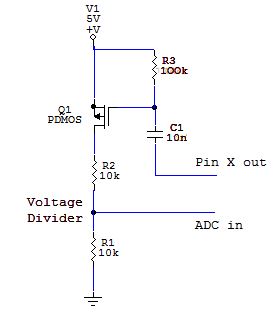
- Vxx Trick.JPG (15.99 KiB) Viewed 1256 times
I just tried to model this in LTSpice but I get strange results
I thought I’d turn on the control signal for 100 microseconds, (actually I used a square wave of period 200 microseconds), but the waveform I get on the middle of the divider is a series of increasing voltage pulses
Maximum voltage I get on the middle of the divider (for 5V input ) is 600mV
I’ve attached my LTSpice file (perhaps I made a mistake)
That opens the Q1 for
time t = aprox R3 * C1.
During that time you have to provide ADC. As it takes say 1us for STM32, you may try with
R3 = 10k C1 = 4n7-10n
to get t = say 100usecs. You may try even smaller t. The goal is to get the smallest t while the measured ADCin is still stable/precise.
After the measurement you do nothing, the C1 discharges, Q1 will be closed and Vxx and the Divider (say 9k/1k) will be switched off from MCU. No current drained.
Good if you want to measure Vxx = 3V on a CRxxxx coin battery from time to time.. Or something like that.
PS: mind the t changes with Vxx a little bit. You need a logic Q1 pmosfet with lowest level threshold, ie. 1.5V.
Below simulation: it took 1usecs to get the ADC Vin stable. And it lasts for 30usecs stable. You do ADC there. R4 and C2 are parasitic for simulation only.
I do not have such low threshold logic level Pmosfet model for simulation, so I used power mosfet instead (not good, it has high threshold voltage and big gate capacitance).
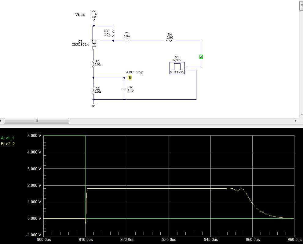
- Zero power DIVIDER.JPG (66.72 KiB) Viewed 1235 times
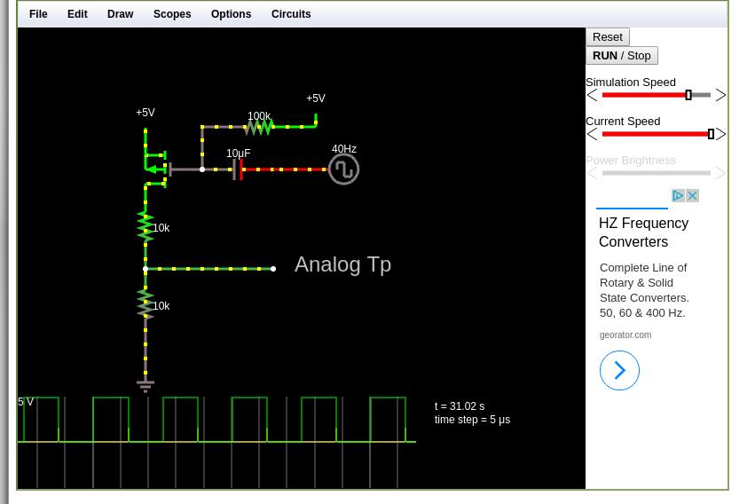
- CircuitSimulator.jpg (46.02 KiB) Viewed 1217 times
Mind there is a current via capacitor C1 as well (during charging/discharging), not only via the divider.
I get a big volt drop across the FET , and I don’t know why.
But I seem to have issues with FETs in LTSpice, which I need to fix sometime.
With some fixes, of course
OMG that graphics, icons, like a children’s toy
Red – Gate, Blue – mid of the Divider, Green – Pinx pulse
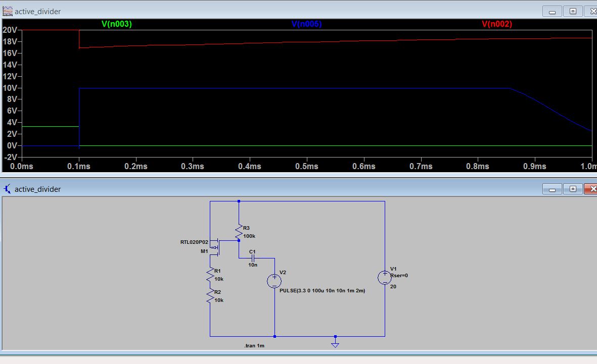
- Roger LTspice Zero Power DIV.JPG (80.51 KiB) Viewed 1194 times
I will try it when I get home
Edit.
No need.
What the problem seemed to be is that the FET needed to have its type set, ie so it modelled a real device, rather than a theoretical “perfect” FET.
I’m not sure why this is, as normal bipolar transistors in LTSpice are OK using the theoretical model most of the time (they seem to be a good close match to real world bipolars)
P.S.
@Pito, which simulator do you normally use ?
I thought LTSpice had a good reputation for accuracy and flexibility, with its main drawback being its very clunky user interface
For Spice circuit simulations (not for the pcb design) I can recommend the “Circuit Maker 2000” (the old one, before Altium took over). The only 2 issues with CM 2k – it is EOL since 2k, and the latest part types are missing (but hundreds still in). But you can add them, afaik.
PS: there is a new edition – CM – 2015 version free, from Altium, you may try. DaveJ did a teardown
![[Pending Enhancement] RTC values resetting](https://sparklogic.ru/wp-content/uploads/2019/11/nucleo-l476rg-zestaw-startowy-z-mikrokontrolerem-z-rodziny-stm32-stm32l476-90x90.jpg)