I know that this ADCTouch library is a kind of implementation of Atmels QTouch and uses some internal capacitor in some way, and I also know it only seems to work on the AVR arduinos … but my question is … has anyone got any idea how I might get this working on the STM32? And if not, are there any other nice ways to get capacitive touch working on these boards without additional hardware?
Here’s a youtube video explaining the principal.
Any ideas how to get this working on a STM32F103 development boards?
Set the pinmode to PULL-UP
Does some sort of ADC conversion using the AVR hardware control registers directly.
Sets the pin to INPUT
Takes an ADC reading using analogRead
It does this a multiple times and averages the result.
The main thing I don’t understand is why the code appears to do one ADC conversion by controlling the hardware directly and then takes the sample using the Arduino API.
Perhaps the first conversion is just a way to delay for a small and fixed period of time.
Or perhaps those AVR register settings do something else to the pin.
I looked at the video,but it does not give any technical details of the principal of operation.
Anyway..
As far as I can see, is the principal of operation is to use the internal pull-up resistor as a charge source, and the ADC is used to measure the voltage across the capacitor, as it charges up.
The latest version of the capacitive touch library seems to be here
https://github.com/PaulStoffregen/CapacitiveSensor
It would need to be modified to work with the STM32
As far as I can see, the platform specific code is in CapacitiveSensor.h
e.g this is the block of code for the ESP8266
https://github.com/PaulStoffregen/Capac … h#L95-L105
A block of code similar to this would need to be added for the LibMaple core or for the official HAL based STM core.
BTW.
If you are intending to port this to the STM HAL based core, you can’t simply use register a addresses as each STM32 MCU series has different base addresses for its GPIO etc. So you’d affectively need to write functions which are wrapped up to look like macros.
Right one is the one proposed by Roger.
For the main question, to have an ADCTouch without hardware, it seems interesting to check if it is possible with STM32 internal circuit.
It seems that the Arduino team use the 2 wire per sensor version.
I’ve taken a look at the description of how the single wire “QTouch” works, according the github repo, and it has the following explanation
Charge the test pin to 5V via pullup resistor (not directly to prevent short circuits)
Discharge the internal ~14pF capacitor
Set the pin to tristate
Connect the 14pF capacitor with the pin so that charge distributes evenly
The important thing to note here, seems to be the ability of the AVR to “Connect the 14pF capacitor with the pin”
This seems to imply that somehow the AVR has an internal capacitor which can be connected to the pin.
I’m not sure where this capacitor is. Its possible that its a byproduct of connecting the ADC, and somehow there is a way to “Discharge” the internal capacitor independently of it being connected to the pin.
Anyway, I’m not sure if this would work on the STM32 as it seems to rely on the internal ADC architecture of the AVR chip.
Also, what I don’t understand is how this can not be effected by mains pickup.
I know that the video shows a 1k resistor in series with the pickup, but this is not really going to damp the mains pickup at all, because the input impedance on the STM32 is many times higher than this (probably 25 x or more high)
I tried writing some code that pulled the pin low and then immediatly sampled the adc until its value had changed by around 1000, but internal capacitance was completely swamped by mains pickup.
If you want a very crude touch sensor, and are mostly indoors i.e somewhere that you will get mains pickup, this works;-)
Input is PA4, and assumes BluePill board with LED on PC13 active LOW
void setup() {

// put your setup code here, to run once:

Serial.begin();

pinMode(PA4,INPUT);

pinMode(PC13,OUTPUT);

}
void loop() {
if (abs(analogRead(PA4) - 2048)>500)
{
digitalWrite(PC13,LOW);
delay(10);
}
else
{
digitalWrite(PC13,HIGH);
}
delay(1);
}
My sketch:
int ref0, ref1;     //reference values to remove offset
int ADCTouch_read(byte ADCChannel, int samples)

{

long _value = 0;

for(int _counter = 0; _counter < samples; _counter ++)

{

pinMode(ADCChannel, INPUT_PULLUP);
analogRead(ADCChannel);
/*

ADMUX |=   0b11111;

ADCSRA |= (1<<ADSC); //start conversion

while(!(ADCSRA & (1<<ADIF))); //wait for conversion to finish

ADCSRA |= (1<<ADIF); //reset the flag

*/
pinMode(ADCChannel, INPUT);

_value += analogRead(ADCChannel);

}

return _value / samples;

}
void setup()

{

// No pins to setup, pins can still be used regularly, although it will affect readings
Serial.begin(9600);
ref0 = ADCTouch_read(A0, 500);    //create reference values to

ref1 = ADCTouch_read(A1, 500);    //account for the capacitance of the pad

}
void loop()

{

int value0 = ADCTouch_read(A0, 100);   //no second parameter

int value1 = ADCTouch_read(A1, 100);   //   --> 100 samples
value0 -= ref0;       //remove offset

value1 -= ref1;
Serial.print(value0 > 40);    //send (boolean) pressed or not pressed

Serial.print("\t");           //use if(value > threshold) to get the state of a button
Serial.print(value1 > 40);

Serial.print("\t\t");
Serial.print(value0);             //send actual reading

Serial.print("\t");
Serial.println(value1);

delay(100);

}
These are the the best explanations I found of the concept:
http://tuomasnylund.fi/drupal6/content/ … le-adc-pin
http://hackteria.org/wiki/QTouchADC_Library_for_Arduino
The guy who wrote another version based on the original arduino library by martin2250, also started this whole project using the same principal based but on a attiny85.
I’ve tried the original library out on a atmega328 (nano) and it works very well with good repeatability and seemingly low noise. How is this? Is the fact that this also works on an Attiny85 due to the same Atmel architecture with the internal 14pF capacitor?
I tried the same thing, but I also plotted the ADC value, by sending it vie Serial and using the Arduino plotter display
I found I get loads of mains pickup, which has a really big effect on the results.
It does detect when you touch the pin, but I think this is mostly due to the mains pickup which is in excess of the supply voltage
The serial plotter for eight touch inputs being touched one after the other looks like this :

- Screen Shot 2017-08-16 at 13.13.16.png (115.93 KiB) Viewed 2458 times
I don’t think it’s just the mains. Today I went to the center of a sports field with a phone and an OTG cable, and it was just as responsive as indoors. I then took it indoors, while keeping it running so it would keep the same reference data (the demo sketch I am using gets reference data on startup, and I started up in the middle of the field), and I didn’t see any of the false positives you’d expect if mains was swamping everything–again, things worked just fine indoors with the same reference data.
I am using a lower activation threshold than the ADCTouch’s demo, 25 instead of 40.
I don’t have an STM32 easily accessible right now (one is inside a project box and another is in the mail).
- photo.jpg (111.63 KiB) Viewed 2318 times
[fpiSTM – Fri Aug 04, 2017 12:20 pm] –
I’ve just replaced
ADMUX |=   0b11111;

ADCSRA |= (1<<ADSC); //start conversion

while(!(ADCSRA & (1<<ADIF))); //wait for conversion to finish

ADCSRA |= (1<<ADIF); //reset the flag
Currently there is a 4.7K resistor between the pin and the alligator clip I am touching, because my STM32 is encased in a hard to open project case, and my PA7 pin happens to have a 4.7K on it.
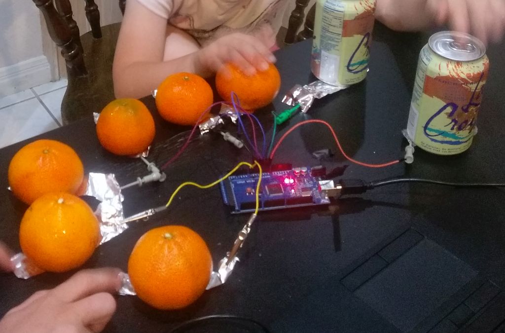
The results are gratifying. Without touch, I am getting output values in the single digits, and when I touch the alligator clip, I am getting around 200. When I attached the alligator clip to an orange at startup (it’s important that whatever one has attached to the pin be there at bootup, so the reference value can take it into account), upon touching the orange, I would get values of around 19 with a light touch and around 30 with a firmer touch. In theory, it should be possible to make a MIDI piano with oranges for keys and variable velocity dependent on how hard one presses!
It seems to work both indoors and outdoors (though I only checked with larger delayMicroseconds() outdoors; I doubt this makes a difference). There is probably quite a bit more to tweak for optimal use, and one should really do this on a pin without a resistor.
Here is my sketch:
int32_t measure(int pin, int samples) {

uint32_t total = 0;

for (int i=0; i<samples; i++) {

pinMode(pin, INPUT_PULLUP);

pinMode(PA6, OUTPUT);

digitalWrite(PA6, 0);

delayMicroseconds(50);

analogRead(PA6);

pinMode(pin, INPUT_ANALOG);

total += analogRead(pin);

}

return total/samples;

}
int32_t base;
void setup() {
delay(2000);
base = measure(PA7, 500);
Serial.println("Start "+String(base));
}
void loop() {
Serial.println(String(measure(PA7, 10)-base));
delay(50);
}
https://github.com/arpruss/ADCTouchSensor
The library works on STM32, AVR and probably any MCU whose internal ADC workings are similar.
On the STM32F103C, it uses the fact that ADC channel 15 appears to be always grounded (it doesn’t connect to a pin), and so it doesn’t require any extra pin. On other devices, you need to specify a sacrificial analog pin which is grounded, and which shouldn’t be connected to anything.
My experience suggests that no debouncing is needed.
Here’s how to use:
#include <ADCTouchSensor.h>

...

ADCTouch button0 = ADCTouchSensor(PA0); // add a sacrificial pin number if needed

ADCTouch button1 = ADCTouchSensor(PA1);

...

button0.begin(); // calibrate touch sensors at startup

button1.begin();

...

if (button0.read() > 40) {

... button pressed ...

}
if (button1.read() > 40) {
... button pressed ...
}
https://github.com/arpruss/capacitive-piano-Arduino
