I am very interested in getting the audio codec on the STM32F4 discovery board working. I love this board for its audio capabilities.
I understand that it reuires I2S (which is on SPI3) and I2C to work with the DAC.
Would it be possible to make a library ?
If so, does anyone have any pointers as to how I would go about doing it using the current STM32Arduino cores done by Roger? (thanks Roger.)
It looks like the Maple RET6 board had I2S
I did a search on “maple I2S” and found
https://ackspace.nl/wiki/DSP_experiments
I don’t known anything about I2S I’m afraid.
You will probably need to read the doc for the F4 from STM , hundreds of pages, to see how to configure and use the I2s port.
Then look at how SPI is implemented as a guide on how to implement I2S.
You may need to add new features to the cores code and headers, if so please let me know what you intend to do on the F4 so I can do an F1 equivalent
My problem is, that I do not own a I2S STM32 board.
I also don’t know how the basics for I2s are in the libmaple implemented.
Good documents to start:
https://www.sparkfun.com/datasheets/Bre … I2SBUS.pdf
http://www.st.com/web/en/resource/techn … 087544.pdf
From the structure, I’ve done following (as I can remember):
Setting up the I2s bus (permanent clock line) and firing an interrupt (I2s buffer (nearly) empty – feeding new data to the bus)
I took a quick look at the master programing reference for the STM32F103 devices
http://www.st.com/web/en/resource/techn … 171190.pdf
And it looks like I2S is implemented as a special mode of the SPI hardware.
So I suspect your best option is to duplicate the SPI libary, and modify it
However looking at the docs, I2S seems to have a layer of protocol on top of the raw transfer of data using clock and data, which you’d need to understand to have a chance of implementing a new library
OK. I’m getting my head around trying to get I2S working on the STM32F4 discovery so we can link to the on board codec.
I2S is linked to SPI3 and it appears SPI3 works as I have done a simple spi3 write test and the clock and MOSI signals appear on my oscilloscope.
To use I2s I have to remap pins from SPI3 to the I2S.
An example I found gives this:
 /* Connect pins to I2S peripheral  */

GPIO_PinAFConfig(GPIOA, GPIO_PinSource4, GPIO_AF_SPI3);

GPIO_PinAFConfig(GPIOC, GPIO_PinSource10, GPIO_AF_SPI3);

GPIO_InitStructure.GPIO_Pin = GPIO_Pin_4;

GPIO_Init(GPIOA, &GPIO_InitStructure);

GPIO_PinAFConfig(GPIOC, GPIO_PinSource12, GPIO_AF_SPI3);

/* CODEC_I2S pins configuration: MCK pin */

GPIO_InitStructure.GPIO_Pin = GPIO_Pin_7;

GPIO_InitStructure.GPIO_Mode = GPIO_Mode_AF;

GPIO_InitStructure.GPIO_Speed = GPIO_Speed_50MHz;

GPIO_InitStructure.GPIO_OType = GPIO_OType_PP;

GPIO_InitStructure.GPIO_PuPd = GPIO_PuPd_NOPULL;

GPIO_Init(GPIOC, &GPIO_InitStructure);

/* Connect pins to I2S peripheral  */

GPIO_PinAFConfig(GPIOC, GPIO_PinSource7, GPIO_AF_SPI3);

/* Enable the CODEC_I2S peripheral clock */
Some thing I researched a little bit: I2S support for any STM32 board will be a “beginning from the sketch”, I didn’t found any related stuff with maple/leaflabs and I2S, there were some plannings years ago, but no single line code written. Even I don’t know if there is any “core” support in the leaflabs core files, so I think the only possibility is to look into the CMSIS/StdPeriphDriver files like:
https://github.com/avikde/koduino/blob/ … f10x_spi.h
and
https://github.com/avikde/koduino/blob/ … f10x_spi.c
There is I2S support included. The advantage is, that you can transfer some of the I2S examples with this lib.
I think this could the way to approaching this.
Keep in mind, what Roger answered to me:
Originally, the files like the ones Avik uses, didnt exist, there were other files but they were copyright STM so could not be used by LeafLabs, hence they wrote their own.
The files that Avikde uses come from the STMCube and are open source (well OK to use), but STM only released the STMCube support for F103 very recently, and according to @westfw, there are still issues with them.
However that was probably 1 month ago
So maybe it’s the better way for I2S only(!) to use the StdPeriph_Driver rather than the leaflabs ones.
I was thinking that starting with doing the setup in a sketch was the way to go also. I’ve amended part of the spi.h & spi.c files but am stuck on how the remap register works. GPIO alternate function low register (GPIOx_AFRL) (x = A..I/J/K) and GPIO alternate function high register (GPIOx_AFRH)
(x = A..I/J)
Let me know how you get on with Koduino
I had a quick look the other day, but the whole repo is generally targeted for the F3. This isnt just the variant folders, the platfrom.txt is has hard coded stuff for the F3, which made it harder to get it to work with the F103
But the F4 is probably OK, because it has a FPU (which was one issue I had when trying to use Koduino on the F103)
Note. I’m not sure the Koduino API is 100% Arduino compatible, I tried to run a simple blink sketch and it didn’t compile because Avik has used his own data type for “Logic” i.e HIGH or LOW, instead of using uint8_t or whatever the normal Arduino files use.
https://github.com/avikde/koduino/tree/ … m32/system
void gpio_set_af_mode(gpio_dev *dev, uint8 pin, int mode) {

gpio_reg_map *regs = dev->regs;
regs->AFR[pin/8] = (regs->AFR[pin/8] & ~(15 << (4*(pin&7)))) | (((mode >> 0) & 15) << (4*(pin&7)));

}
Matthias has done it on his Nucleo board.
It’s probably best to download the programming manual PDF for the F4 from the STM site ( its hundreds of pages ) and see if there are any limitations to remapping, I had the feeling that not pins can’t be arbitrarily remapped to any other pin.
Also, Im not sure why you want to remap, is this because of the hardware on the Discovery board ?
If so, try to see if there is any low level C code examples from STM for I2S on the Discovery board, as they would need to do the same thing, so you could see what they did
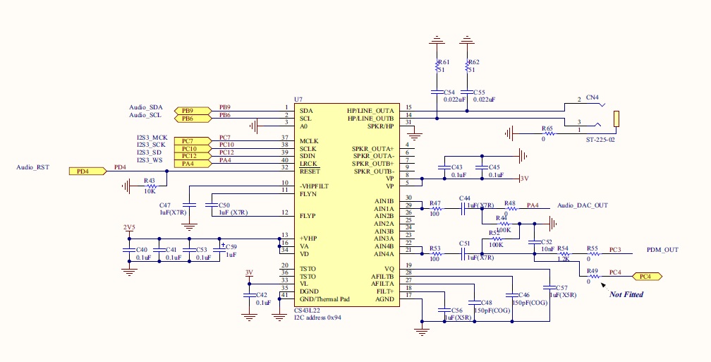
- F4 discovery codec pinout
- CODEC.jpg (98.03 KiB) Viewed 2692 times
Thats excellent news.
Sorry I cant help with I2S, but I don’t know anything about that protocol, but I did buy some I2S audio codec boards a few months ago, so it will be intresting to see if any of your code works on the F103
Well, I have an F4, but a several people are playing with F013V series boards, which I think may have I2S (I’d need to double check)
I’m not sure about I2C. It also kind of depends if you just mean Wire , which was implemented as a software bit banged version or if you mean “HardWire” which is the true hardware I2C in the uP
I suspect the software one should work, as it did on the F103 (well it had a very minor bug that stopped the I2C Scanner demo from working, but apart from that it was OK)
Thats all I know..
#define I2C_DELAY(x) do{for(int i=0;i<x;i++) {asm volatile("nop");}}while(0)I seem to have I2C working. I see the clock signal and am using the i2c_master_xfer function to send address & data bytes to the codec. I see them on the oscilloscope.
However, I am close to giving up as I can’t for the life of me get the I2S MCLK working!!!!!
The mclk pin is on GPIOC7 which I have configured as an AF PP output and it is remapped to SPI3.
I have tried setting the PLLI2s to on and several different combinations of setting registers but I still see a flat line on my oscilloscope where I should see a nice clock wave….
its doing my head in.
I can only help theoretically:
So (I personally don’t like the term “I2c” and “I2s” – too close together): I2c is working (with wire.h in software mode, as I suspected…)
What I2s module/chip do you using? I’m a little bit confused, because you talk about I2s and I2c in one sentence. If you can tell me the chip, I can read the datasheet.
I have an I2S board (I think)… I’ve never tried it.
I will see if I have some time at the weekend to look at I2S
mubase can you post all your code
I think the thing with I2S is that its more similar to SPI in its electrical connections than it is to I2C
well, STM have it on the SPI port, so there must be a reason for that
I’m using an STM32F4 discovery board. The microcontroller is an stm32f407vgt. The board has an on board audio codec, the cirrus c43l22. It uses I2S as its audio controller and I2C to communicate with the codec’s control signals.
the code is here::
void setup()

{

i2s.end();   // de init

gpio_set_mode(GPIOD,4,GPIO_OUTPUT_PP);  // codec reset pin
//i2c pin modes
gpio_set_mode(GPIOB,6,GPIO_AF_OUTPUT_OD); // i2c clk
gpio_set_mode(GPIOB,9,GPIO_AF_OUTPUT_OD); // i2c data
// i2c remap to B
gpio_set_af_mode(GPIOB,6,4);
gpio_set_af_mode(GPIOB,9,4);
//enable i2c & i2s clocks which are probably enables already but just to be sure
rcc_clk_enable(RCC_I2C1);
rcc_clk_enable(RCC_SPI3);
RCC_BASE->CFGR &=(1<<(uint32)23); // pll i2s
RCC_BASE->CR |=(1<<(uint32)26);
RCC_BASE->CR |= (0b1 << 26);
/* PLLI2S clock used as I2S clock source */
RCC_BASE->CR |=(1<<16); //HSE on
RCC_BASE->CR |=(1<<24); // pll on
/* Enable PLLI2S */
RCC_BASE->CR |= (0x0f039583); // from debug
// while((RCC_BASE->CR & RCC_PLLI2SRDY) == 0)
// {
// }
//i2s pins
gpio_set_mode(GPIOC,10,GPIO_AF_OUTPUT_PP);
gpio_set_mode(GPIOC,12,GPIO_AF_OUTPUT_PP);
gpio_set_mode(GPIOC,7,GPIO_AF_OUTPUT_PP);
//set remap to spi3
gpio_set_af_mode(GPIOA,4,6);
gpio_set_af_mode(GPIOC,7,6);
gpio_set_af_mode(GPIOC,10,6);
gpio_set_af_mode(GPIOC,12,6);
//gpio turn off codec for now
gpio_write_bit(GPIOD,4,0);
//configure i2s
/* SPI3_BASE->I2SCFGR |= 0b0000111000000000;
SPI3_BASE->I2SPR |= 0b0000001100000011;
SPI3_BASE->I2SPR |= 0b0000001100000011;*/ prescaler and turn on i2S MCLK
SPI3_BASE->I2SCFGR |=(SPI_I2SCFGR_I2SCFG_MASTER_TX); // i2s in master transmitter mode.
//i2c setup
i2c_set_clk_control(I2C1,1);
i2c_set_input_clk(I2C1,3);
i2c_enable_ack(I2C1);
i2c_master_enable(I2C1, 0);
i2c_peripheral_enable(I2C1);
codec_ctrl_init();
//i2s begin
i2s.begin();
}
But in the f103 manual it says
MCK: Master Clock (mapped separately) is used, when the I2S is configured in master mode (and when the MCKOE bit in the SPI_I2SPR register is set), to output this additional clock generated at a preconfigured frequency rate equal to 256 × FS, where FS is the audio sampling frequency
But you appear to be doing that in your code
I know some things can’t be done while the SPI is enabled, so perhaps try disabling and re enabling SPI 3 after all other changes
Or preferably disable it at the start
Make all the changes and re enable
If you have not already been doing that (its a bit hard to tell in the code just by looking at bit patterns, its best to do #defines for bit patterns for readability
void spi_peripheral_enable(spi_dev *dev) {

bb_peri_set_bit(&dev->regs->CR1, SPI_CR1_SPE_BIT, 1);

}I added a function to the SPI.C file that sets up I2S to be enabled in MAster Xmit mode, 16bit phillips standard.
void i2s_peripheral_enable(spi_dev *dev) {

bb_peri_set_bit(&dev->regs->I2SCFGR, SPI_I2SCFGR_I2SE_BIT, 1);

SPI3_BASE->I2SCFGR |=(SPI_I2SCFGR_I2SE);

SPI3_BASE->I2SCFGR |=(SPI_I2SCFGR_I2SCFG_MASTER_TX);

SPI3_BASE->I2SCFGR |= (SPI_I2SCFGR_I2SMOD_I2S );

SPI3_BASE->I2SCFGR |= ( SPI_I2SCFGR_I2SSTD_PHILLIPS);

SPI3_BASE->I2SCFGR |= ( SPI_I2SCFGR_DATLEN_16_BIT);

SPI3_BASE->I2SCFGR |= (  SPI_I2SCFGR_CKPOL_LOW);

SPI3_BASE->I2SCFGR |=(0b000011100000000);
SPI3_BASE->I2SPR |= (00000011100000011);   // set for mck on and 48K samplerate
}
Thanks fantastic news
When you get chance can you zip up and post your new functions (no rush)
I will dig out my external I2S hardware modules and work out what chip they use
I'm using an STM32F4 discovery board. The microcontroller is an stm32f407vgt. The board has an on board audio codec, the cirrus c43l22. It uses I2S as its audio controller and I2C to communicate with the codec's control signals.I just checked, and my modules are not I2S ![]()
I have the vs1053 http://www.vlsi.fi/en/products/vs1053.html
I2S interface for external DAC
I was confused because the I2S is for them to drive an external DAC, not for them to be used a DAC ![]()
It could be that I can just use the Adafruit lib
https://github.com/adafruit/Adafruit_VS1053_Library
I will need to see if I can get a I2S dac on its own.
And in the mean time, that lib (when I have time)
If you own the LCsoft VS1053 module, grab out your soldering iron and read this, otherwise you can’t use it for mp3:
http://www.bajdi.com/lcsoft-vs1053-mp3-module/
I got my lcsoft module working a while ago, I think, I didn’t tried it out on maple, I’ve zipped my UNO testing sketches for you.
The VS1053 is a cool unit from the specs: playing various compressed and not compressed audio formats, recording audio…. the advantage is, that every data stream goes via the MCU so you can control the source, have access to the SD-card file names, maybe some DSP hacks (if it works without FPU?)
If you need – or just wanna play – with a simple 16bit I2s audio DAC look out for the PT8211. They are totally cheap, easy to setup and ok sounding only thing to know about them: They use the Least Significant Bit Justified (LSBJ – or called “japanese input format”) format, not I2s. But this should be done only setting a single bit in the register. (There are about 3-4 I2S similar audio stream formats and as I know every MCU with I2s support can handle most of them)
Edit: Yes you can use the adafruit library I also used it in one of my test codes.
Edit 2: The VS1053 is a simple SPI controlled device, not I2s
Yes.
That’s the board I have.
I just read the article… So I need to solder a couple of the pins together .. No problem.
I bought a cheap’ish USB microscope the other day, so I can view things close up on a minor while I solder, as otherwise even with some x3 glasses I have, its really hard to solder on those tiny little chip
BTW. I bought the board to play MP3’s, so using I2S was not my primary concern.
Thanks for the Uno sketches. I’m not sure when I will have time to try them.
Things are a bit busy with work, as I started a new project a few days ago, and I’m still trying to work out what is required or how to program it ![]()
Thanks again
Roger
PS. I will create an Off Topic section now that I remember it !
One problem i am having is with outputting data through the I2S MOSI. I understand it needs to be done from an ISR but I’m not sure how to set up an interrupt function for the SPI when tx is empty.
Can anyone help me on this?
I’ve had a look at isr.s and the vectors but don’t know how to set them up…
You probably should look at the DMA stuff
VictorPV got it working on the F103, but he used the old / deprecated version of the dma functions (as they seemed to be easier to get to work)
On the F4 there is a new concept of “DMA Pipes” that leaflabs changed to using, because it was better suited to the F4
Apart from that I think you’d need to look at the NVIC code, because I think the NVIC handles all interrupts, rather than individual sub sections
e.g. I don’t think SPI / I2S has a register for the ISR, I think the register is in the NVIC section
(not sure if any of that helps ![]()
Edit.
You can also just poll for SPI being ready
If you look in the SPI lib in the F103 it checks for 2 different things after it writes a byte, before the function exits. I think one of the flags it waits in a while loop for is the data ready flag, i.e its ready for more data
Obviously this is not at all efficient.
On this point, I can’t help you further, without I2s-STM32 board.
I think the best idea would be to google “stm32 i2s demo” or something, I found things like this:
http://electronics.stackexchange.com/qu … rupt-usage
https://github.com/bjornfor/stm32-test/ … eInterrupt
http://ebrombaugh.studionebula.com/synth/stm32f4_codec/
It should be possible to examine the code examples of the links above so you get some hints how to manage the irq/buffer stuff.
Roger: You are right with DMA and I2s. You get best performance if you have a constant data stream (f.e. from sd-card). I didn’t play with that on my pic32, because I use “real time audio calculation” so each sample is calculated in each irq trigger, so the stream isn’t predictable.
Roger: I use something like this for fine soldering:
http://www.aliexpress.com/item/Multi-fu … 04310.html
It has a dual magnifying glass (3.5x and 12x) and LED light. Even TFQ64 (didn’t try 100 yet) won’t be a problem to solder with it. You only have to disassembly the soldering iron holder if you don’t like the smell of burnt plastic. (totally design flaw)
I have quite a large illuminated magnifying glass, but its not high magnification.
I also use x3 “reading” glasses – which would be terrible for “reading” but are quite useful for x3 magnification (though you get dizzy if you try to wear them and walk around)
I also have a x 10 jewelers eye glass
and also this usb microscope for very small things (though there is some lag onto the PC screen)
http://www.ebay.com.au/itm/2MP-USB-Digi … 27daea5d93

Also take a look at
https://github.com/leaflabs/libmaple/bl … rt-dma.cpp
and
http://forums.leaflabs.com/topic.php?id=1882
PS. I think I said “pipe” before. I can see now its “tube” ![]()
I think I managed to get a DMA tube working to Hardware serial, but I don’t think the leaflabs example worked in its existing form
But its worth trying
I probably posted something on the Arduino.cc forum, months ago about it
But its such a huge thread I’m not sure If I can find it.
Edit.
found it
http://forum.arduino.cc/index.php?topic … msg2141899
I’m assuming that the F4 repo was taken from a late enough version that it includes DMA tubes, but I’ve not had chance to look
PS. MuBase
If you have any DMA questions, its also worth taking to VictorPV has he did all of the work getting SPI DMA to work on F103 and I’m sure a lot of the things he learned would be applicable to your DMA on the F4
Ah, Also, I think the F4 may gave a DMA FIFO, its worth checking. The Teensy has one (not STM) but I know the F103 doesnt
Another problem: the microscope wouldn’t be mine: little daughter, insects, inquiring minds
…but I added it to my wish list
So I’m using the i2c library and this function to talk to the codec over i2c:
 void writecsl(uint8 reg, uint8 data) {

/* all i2c transactions send and receive arrays of i2c_msg objects */

i2c_msg msgs[1]; // we dont do any bursting here, so we only need one i2c_msg object

uint8 msg_data[2]= {reg,data};
//msg_data = {reg,data};
msgs[0].addr = 0x94;
msgs[0].flags = 0; // write
msgs[0].length = 2;
msgs[0].data = msg_data;
i2c_master_xfer(I2C1, msgs, 1,5);
}
It looks like the libraries e.g wire were not ported to F4 by the AeroQuad team (who did the port from the original/old version of libmaple)
I think your best option is just to copy the Wire library from the F103, and make a libraries folder in your STM32F4 folder.
It’s software i2c so would work for the F4. It uses a timing loop to control the speed.
If you look in wire.h
There is a macro that is a for loop for the delay
And the speed is defined by SOFT_STANDARD or SOFT_FAST
by default SOFT FAST is used, so just put a number like 100 in there and give it a go.
However unless you have a scope its going to be a bit hard to work put the speed.
But I estimate that 50 on a 168mhz board , should be less than 100khz,
E.g 16 is 100khz at 72mhz
So
168/72 x 16 = 37 then allowing for the other instructions to be faster, i would try a count of 50
#define SOFT_STANDARD 16

#define SOFT_FAST 0
//#define I2C_DELAY(x) {uint32 time=micros(); while(time>(micros()+x));}
#define I2C_DELAY(x) do{for(int i=0;i<x;i++) {asm volatile("nop");}}while(0)
The wire library you suggested is giving results on my oscilloscope.
I think I’m about half way there.
One more thing that is bugging me is why I can’t seem to send anything over the spi(i2s) MOSI that I can see on my scope.
I see all the other signals (sck, WS, MCLK) but nothing on PC12 which is the MOSI pin.
I have tried spi_tx and even writing directly to the DR register but with no results when the I2S is configured.
If I configure a normal spi then everything is OK and I can send anything over MOSI….
Do you mean you are trying to use SPI as well as I2S or do you mean one of the I2S signals is not working.?
Either way, the only thing I can suggest is to look at the register setup for the SPI and also look at the RCC setup, in case something in the RCC needs to be configured as well
I think it may be a question for STMs own community support forum. But I wouldn’t mention you are using th Arduino IDE etc, just detail what registers you have setup etc, and see if they can tell you what you’ve missed
After failed attempts at getting Wire to work I went back to the Maple Audiocodec code from http://wiki.openmusiclabs.com/wiki/AudioCodecShield
The code used to communicate with the I2C controls of the Wolfson codec on the DSP board uses bit banging with a poll to check for reciept of data.
I changed the code to reflect a startup sequence and to output a continuous tone using the codec’s built in beep function:
// i2c start condition

char i2cbb_start(void) {

if (digitalRead(SDA_PIN) == 0) { // check if data line released

return -1; // end with failure if not released

}

else if (digitalRead(SCL_PIN) == 0) { // check if clock line released

return -2; // end with failure if not released

}

else { // send start condition

digitalWrite(SDA_PIN, LOW);  // data low

mydelay(10); // delay

digitalWrite(SCL_PIN, LOW); // clock low

mydelay(10); // delay

return 1; // set state to success

}

}
// i2c stop condition
void i2cbb_stop(void) {
digitalWrite(SDA_PIN, LOW); // pull data low
mydelay(10); // delay
digitalWrite(SCL_PIN, HIGH); // release clock line
mydelay(10); // delay
digitalWrite(SDA_PIN, HIGH); // release data line
mydelay(40); // delay to make sure a new data transfer doesnt occur too quickly
}
// i2c data send
char i2cbb_send(unsigned char data) { // clock out data
unsigned char state = 0; // initialize return state
unsigned char i;
for(i = 8 ; i > 0 ; i--) {
digitalWrite(SDA_PIN, (data & (1 << (i - 1))));
mydelay(10);
digitalWrite(SCL_PIN, HIGH);
mydelay(10);
digitalWrite(SCL_PIN, LOW);
}
// check for ack
digitalWrite(SDA_PIN, HIGH); // release line
mydelay(10); // wait a bit
unsigned char d = 30; // initialize timeout
while(digitalRead(SDA_PIN) == 1){ // wait for ack
// timeout in case of nack
togglePin(LED_PIN);
d--;
if (d == 0) {
state = 2; // set i2c state to nack
break;
}
}
// clock the ack or nack
digitalWrite(SCL_PIN, HIGH);
mydelay(10);
digitalWrite(SCL_PIN, LOW);
// make sure line is released
d = 30;
while(digitalRead(SDA_PIN) == 0){
// timeout in case of failure
togglePin(LED_PIN);
d--;
if (d == 0) {
state = 3; // set i2c state to no line release
break;
}
}
if (state > 1) { // send stop if failure
i2cbb_stop();
}
else { // set state to success
state = 1;
}
return state;
}
// full i2c protocol for 3 byte transfer
unsigned char i2cbb(unsigned char reg, unsigned char data) {
if (i2cbb_start() != 1) { // send start condition
return 2;
}
else if (i2cbb_send(ADDR) != 1) { // send address and write bit
return 3;
}
else if (i2cbb_send(reg) != 1) { // send register to write to
return 4;
}
else if (i2cbb_send(data) != 1) { // write data to register
return 5;
}
else {
i2cbb_stop(); // send stop condition
return 1;
}
}
// each register retries until success
// if communication fails the device will hang
void codec_maple_reg_setup(void) {
gpio_write_bit(GPIOD,4,1);
while (i2cbb(0x02, 0x01) != 1) { // power save registers -> all on
delay(10);
}
while (i2cbb(0x0d, 0x01) != 1) { // digital data format -> 16b spi mode
delay(10);
}
while (i2cbb(0x00, 0x99) != 1) { // left input configure
delay(10);
}
while (i2cbb(0x47, 0x80) != 1) { // right input configure
delay(10);
}
while (i2cbb(0x032, (1<<7)) != 1) { // left headphone configure
delay(10);
}
while (i2cbb(0x32, (0<<7)) != 1) { // right headphone configure
delay(10);
}
while (i2cbb(0x00, 0x00) != 1) { // digital pathway configure
delay(10);
}
while (i2cbb(0x04, 0xaf) != 1) { // analog pathway configure
delay(10);
}
while (i2cbb(0x0d, 0x70) != 1) { // analog pathway configure
delay(10);
}
while (i2cbb(0x05, 0x81) != 1) { // analog pathway configure
delay(10);
}
while (i2cbb(0x06, 0x07) != 1) { // analog pathway configure
delay(10);
}
while (i2cbb(0x0a, 0x00) != 1) { // analog pathway configure
delay(10);
}
while (i2cbb(0x27, 0x00) != 1) { // analog pathway configure
delay(10);
}
while (i2cbb(0x1a| 0x80, 0xaa) != 1) { // analog pathway configure
delay(10);
}
while (i2cbb(0x1f, 0x0f) != 1) { // analog pathway configure
delay(10);
}
//beeps
while (i2cbb(0x1c, 0b01101111) != 1) { // analog pathway configure
delay(10);
}
while (i2cbb(0x1d, 00000110) != 1) { // analog pathway configure
delay(10);
}
while (i2cbb(0x1e, 11000000) != 1) { // analog pathway configure
delay(10);
}
while (i2cbb(0x02, 0x9e) != 1) { // analog pathway configure
delay(10);
}
/*
#if SAMPLE_RATE == 88
while (i2cbb(0x10, 0xbc) != 1) { // clock select 88.2kHz
delay(10);
}
#elif SAMPLE_RATE == 44
while (i2cbb(0x10, 0xa0) != 1) { // clock select 44.1kHz
delay(10);
}
#elif SAMPLE_RATE == 22
while (i2cbb(0x10, 0xe0) != 1) { // clock select 22.05kHz
delay(10);
}
#elif SAMPLE_RATE == 8
while (i2cbb(0x10, 0xac) != 1) { // clock select 8.018kHz
delay(10);
}
#elif SAMPLE_RATE == 2
while (i2cbb(0x10, 0xce) != 1) { // clock select 2.45kHz
delay(10);
}
#endif
*/
// while (i2cbb(0x12, 0x01) != 1) { // device enable
// delay(10);
// }
}
How do you managed the I2S connection? Which library do you use for that?
The pins for spi3 are set up in AF mode as AF_OUTPUT_PP.
//set remap to spi3

gpio_set_af_mode(GPIOA,4,6);

gpio_set_af_mode(GPIOC,7,6);

gpio_set_af_mode(GPIOC,10,6);

gpio_set_af_mode(GPIOC,11,6);

gpio_set_af_mode(GPIOC,12,6);
//i2s pins
gpio_set_mode(GPIOC,10,GPIO_AF_OUTPUT_PP);
gpio_set_mode(GPIOC,12,GPIO_AF_OUTPUT_PP);
gpio_set_mode(GPIOC,11,GPIO_INPUT_FLOATING);
gpio_set_mode(GPIOC,7,GPIO_AF_OUTPUT_PP);
gpio_set_mode(GPIOA,4,GPIO_AF_OUTPUT_PP);
By doing some debugging of the example on Mind Dump’s blog (Configuring STM32f4 for Audio) and checking the register values it turns out that my I2S Configuration registers weren’t being set up properly.
Looking at the registers I noticed that the I2S wasn’t being set up in Master Transmit mode.
I found out that it was because in my function:
//changed for i2s -06/05/2015   s.scutt (mubase)

void i2s_peripheral_16_bit_master(spi_dev *dev) {
bb_peri_set_bit(&dev->regs->I2SPR, SPI_I2SPR_MCKOE_BIT, 1); // turn on mclk
SPI3_BASE->I2SCFGR |=SPI_I2SCFGR_I2SCFG_MASTER_TX; // master xmit
SPI3_BASE->I2SCFGR |= SPI_I2SCFGR_I2SMOD_I2S ; // i2s mode
SPI3_BASE->I2SCFGR |= SPI_I2SCFGR_I2SSTD_PHILLIPS; // phillps standard
SPI3_BASE->I2SCFGR |= SPI_I2SCFGR_DATLEN_16_BIT; // datalength 16 bit
SPI3_BASE->I2SCFGR |= SPI_I2SCFGR_CKPOL_LOW; // cpol low
}
I am convinced that when people using more these I2s boards that we are fall back to your researches about getting I2s working! Maybe you have time to put a *.zip file of all your working codes to the “code snipplets” section?
(or you can also provide me a ZIP, that will be fine too)
Thanks in advance,
I will push the whole F4 folder to my github later.
Cheers!
Steve.S (mubase)
In fact, I’m not looking for your I2S lib, but to the Wire lib under F4. I’ve took a copy of the F1, but it doesn’t seems to work properly as my MCP23017 doesn’t blink my leds.
It is actually working when I’m using STM32F4xx_DSP_StdPeriph_Lib_V1.4.0 platform.
Something that I saw is that the Wire lib from stm32duino doesn’t seems to initialize GPIOs with PullUps like the StdPeriph is doing, I had to add some externally, but still doesn’t work.
I guess I have to figure out …
i then used the ‘import library’ menu option in the ide to bring up the wire libraries.
The thing is, I didn’t actually use the wire library functions to talk to the codec. I couldn’t seem to get them to work.
In order to talk to the codec I used code from an STM32 Wolfson codec example BUT I needed to initialise the I2C by using Wire.begin().
I didnt use Wire.write(), Wire.BeginTransmission() etc…
So, if you don’t use the Wire lib other than Wire.began(), maybe you don’t need it at all ?
At the begining, my tree didn’t have any Wire under stm32f4 folder, so I did a copy from the stm32f1 like you did.
I’ve plugged my FX2 capture board on the bus and analyse it with pulseview-sigrok, the stm32 output something but not decodable I2C stream, it doesn’t match at is supposed to be send, it is almost pure garbage.
With STM32F4xx_DSP_StdPeriph_Lib_V1.4.0, the I2C protocol is clear and consistent, but, of course, it is done by stm32 hardware, not software bitbanging.
I guess I will have to switch to another lib, but it strange if it is actually working on F1 …
// I2C Codec setup functions. Code adapted from http://www.openmusiclabs.com/projects/codec-shield/
#define ADDR 0x94 // i2c address and write bit
#define SDA_PIN 25 // i2c data line
#define SCL_PIN 22 // i2c clock line
#define LED_PIN 60 // board led pin
void mydelay(unsigned char t) {
while((t << 4) > 0) {
togglePin(LED_PIN);
t--;
}
}
// i2c start condition
char i2cbb_start(void) {
if (digitalRead(SDA_PIN) == 0) { // check if data line released
return -1; // end with failure if not released
}
else if (digitalRead(SCL_PIN) == 0) { // check if clock line released
return -2; // end with failure if not released
}
else { // send start condition
digitalWrite(SDA_PIN, LOW); // data low
mydelay(10); // delay
digitalWrite(SCL_PIN, LOW); // clock low
mydelay(10); // delay
return 1; // set state to success
}
}
// i2c stop condition
void i2cbb_stop(void) {
digitalWrite(SDA_PIN, LOW); // pull data low
mydelay(10); // delay
digitalWrite(SCL_PIN, HIGH); // release clock line
mydelay(10); // delay
digitalWrite(SDA_PIN, HIGH); // release data line
mydelay(40); // delay to make sure a new data transfer doesnt occur too quickly
}
// i2c data send
char i2cbb_send(unsigned char data) { // clock out data
unsigned char state = 0; // initialize return state
unsigned char i;
for(i = 8 ; i > 0 ; i--) {
digitalWrite(SDA_PIN, (data & (1 << (i - 1))));
mydelay(10);
digitalWrite(SCL_PIN, HIGH);
mydelay(10);
digitalWrite(SCL_PIN, LOW);
}
// check for ack
digitalWrite(SDA_PIN, HIGH); // release line
mydelay(10); // wait a bit
unsigned char d = 30; // initialize timeout
while(digitalRead(SDA_PIN) == 1){ // wait for ack
// timeout in case of nack
togglePin(LED_PIN);
d--;
if (d == 0) {
state = 2; // set i2c state to nack
break;
}
}
// clock the ack or nack
digitalWrite(SCL_PIN, HIGH);
mydelay(10);
digitalWrite(SCL_PIN, LOW);
// make sure line is released
d = 30;
while(digitalRead(SDA_PIN) == 0){
// timeout in case of failure
togglePin(LED_PIN);
d--;
if (d == 0) {
state = 3; // set i2c state to no line release
break;
}
}
if (state > 1) { // send stop if failure
i2cbb_stop();
}
else { // set state to success
state = 1;
}
return state;
}
// full i2c protocol for 3 byte transfer
unsigned char i2cbb(unsigned char reg, unsigned char data) {
if (i2cbb_start() != 1) { // send start condition
return 2;
}
else if (i2cbb_send(ADDR) != 1) { // send address and write bit
return 3;
}
else if (i2cbb_send(reg) != 1) { // send register to write to
return 4;
}
else if (i2cbb_send(data) != 1) { // write data to register
return 5;
}
else {
i2cbb_stop(); // send stop condition
return 1;
}
}
// each register retries until success
// if communication fails the device will hang
void codec_reg_setup(void) {
gpio_write_bit(GPIOD,4,1);
while (i2cbb(0x02, 0x01) != 1) { // power save registers -> all on
delay(10);
}
while (i2cbb(0x00, 0x99) != 1) { //
delay(10);
}
while (i2cbb(0x47, 0x80) != 1) { // inits
delay(10);
}
while (i2cbb(0x0d, 0x03) != 1) { // playback ctrl
delay(10);
}
while (i2cbb(0x32, (1<<7)) != 1) { // vol
delay(10);
}
while (i2cbb(0x32, (0<<7)) != 1) { // vol
delay(10);
}
while (i2cbb(0x00, 0x00) != 1) { // inits
delay(10);
}
while (i2cbb(0x04, 0xaf) != 1) { // power ctl
delay(10);
}
while (i2cbb(0x0d, 0x70) != 1) {
delay(10);
}
while (i2cbb(0x05, 0x81) != 1) { // clocking
delay(10);
}
while (i2cbb(0x06, 0x07) != 1) {
delay(10);
}
while (i2cbb(0x0a, 0x00) != 1) {
delay(10);
}
while (i2cbb(0x27, 0x00) != 1) {
delay(10);
}
while (i2cbb(0x1a| 0x80, 0x0a) != 1) { // both channels on
delay(10);
}
while (i2cbb(0x1f, 0x0f) != 1) {
delay(10);
}
while (i2cbb(0x02, 0x9e) != 1) {
delay(10);
}
}
I found the problem : shame on me, stupid junior mistake !
I simply had crossed the default pins for SCL and SDA in the Wire.h when I copied the file from F1 folder into the F4…