I bought a voltmeter on eBay the other day thinking it had a STM8, which I could reprogram (as its been hacked before and there is source code available to re purpose the 3 digit display to do anything that the STM8 is capable of…
However, like I said, its not got an STM8 and the chip has been sanded so there aren’t any markings ![]()
But looking at the PCB has does throw some light on what how it works.
Power in via red and black wires. I don’t think the LED is voltage regulated as it gets brighter as more voltage is applied.
I think R15 and R16 must be the sense input divider, i.e 8.2k / 120k , but also that R12 and R13 end up in parallel with R16, but are much higher values, i.e R12 is 240k and R13 is 510k (if I’m reading the values correctly)
So perhaps R12 and R13 are some sort of calibration ?
BTW the red wire hides a track down and then up the left side of the photo, which is the power input which eventually gets to the 5V reg.
So what I can do is remove R3 and use VT as the input, if I want to use this as a current meter.
As a matter of interest I shorted the missing S1 through an analog current meter and it drew very little current , so I soldered it to simulate a closed switch and the range on the meter gets even more sensitive than before. As far as I can tell its 4 times more sensitive with the switch closed
Anyway. I wanted to make a current meter that will read 0 to 30mA, so I think armed with this knowledge I should be able to convert it, as I can set it to 4 x the normal range and the input voltage that gives a reading of 30.0V is 7.5V
Hence the input pin of the chip is 1/(1/8.2k + 1/240k + 1/510k) / 120k * 7.5 v = 0.487V (if my maths are correct)
So…
Ohms law…
R = V / I
R = 0.487 / 0.03
R= 16.23 ohms.
Which I can probably make 18 ohms in parallel with 180 ohms to be within 1% of the desired resistance.
BTW. I looked at R11 the variable resistor and U2, but I don’t think this is an adjustment, I think its an alternative voltage regulator
Well I guess if the overall voltage changes so does the voltage reference, but its probably easier to just modify the input resistors to get the meter calibrated as a current meter
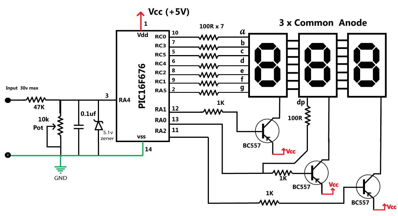
This for example uses a PIC16F676 (right number of pins for your board, but the ADC is on the wrong pin) More details here.
I thinks I should be able to convert it to a current meter, by changing the analog components, but its a shame they always sand off the part numbers, so that its hard to tell what the main chip is, and whether it can be modified.
There are so many microcontrollers, that it really could be anything.
If I get time, I will try to blog my results, and possibly do a video in case anyone else wants to modfiy these volt meters to change their range, or make them into a current meter
I’d like to use a hall effect sensor, but the only ones I’ve seen on eBay are designed to measure large currents and I think include an internal shunt inside the IC
Do you know of one that measures for example up to 100mA ?
http://www.ebay.com/itm/1-Pcs-BI-TECHNO … 1778517512
We used to use these at a company I worked at, but of course much larger currents.
Michael
I’d like to use a hall effect sensor, but the only ones I’ve seen on eBay are designed to measure large currents and I think include an internal shunt inside the IC
Do you know of one that measures for example up to 100mA ?
I already did the maths and I need an about a 16 ohm shunt in order to get the meter to read millamps instead of volts (well thats if my maths is correct)
i.e it needs to think that the voltage across the shunt is the voltage 1V when the current is 1mA
I’ll do some tests using an 18 ohm resistor in parallel with a 180 ohm resistor, as I think this gives me approximately what I need
Actually, its a long story… But I think the current I am reading is actually PWM at 20kHz.
The board has a cap from the input to GND which would provide some smoothing, but probably not enough as I’m adding the 16 ohm resistor to gnd as the shunt.
So I suspect I’ll need to feed the ADC via a 1k resistor (or some other value), so that I have a low pass filter to read the average current of the PWM.
I vaguely recall something about the RMS voltage / current of a square wave not being the same value as a sine wave, so I’ll need to do some research into how accurate that measuring PWM is using a low pass filter to average the PWM.
Edit
Actually, I’m not sure now whether I can even use this meter for what I had intended, because the whole module is not isolated. i.e I could connect a DMM to measure this, because it runs from a battery, but to use one of these modules to measure current, I have to be able to connect it between the load and the 0V (GND) supply of the meter.
And I have a feeling that where I want to use it, does not meet that criteria.
Anyway. It doesnt do any harm to have a panel DVM kicking around ![]()
https://www.adafruit.com/products/158
I have two of these – just came yesterday.
I think that a wire carrying 100mA, coiled in a slit-core ferrous core (perhaps adapted from one of those ferrite filters on power and USB cords wold do as the core. Sensor (transistor sized) in the gap of the core. With enough turns in the core, I read you can get down to 100mA sensing.
On this page, scroll down to the mention of a white paper. In that document, page 3-18 is a discussion and drawing.
I can try this using one I have, or send you one.
I also have 2 of these current transformers that output 1V with 5A flowing in the conductor.
And there’s the previously mentioned Adafruit USB power gauge… range is 0 to 500mA as scaled for the ADC in the AVR.
https://www.adafruit.com/products/1549
I have one and use it often. Analog signal is handy. UART text comes out too, showing V and mA.
Which could be hacked. It has a shunt sensor. See schematic at git hub page referenced here:
https://github.com/adafruit/USB-Power-G … %20sch.png
The shunt sensor is
http://www.ti.com/product/ina169
Shunts are normally less than 1 ohm so as to not cause a significant IR drop in the circuit. I’ve done that with an ordinary 1/4 watt 1 ohm resistor and a scope that shows a few 10’s of mV.
I’m not sure if that TI part has an isolated input.
But either way, I don’t think any of this would work with my meter unless I could scale it correctly.
I’ve re-ordered some more meters, which look a lot more like they are based on the STM8, which would be reprogrammable
So I’ll wait until they turn up in 2 or 3 weeks and look at this again.
In the mean time I have a 30mA analog meter I can use, it just doesn’t look so nice ![]()
And I’ll keep looking for a hall effect device as I like the idea of the isolation you get with such a device.
I’ve lost the premise here… I mistakenly thought you wanted to measure up to 100mA and get that in digital form. So I was, right or wrong, on the track of doing that without using an ammeter item – just obtain an analog voltage representative of the current flow magnitude. Then feed the voltage to an ADC in a microprocessor. Using either the T.I. part of the hall effect device I mentioned which looks like a transistor, and is placed near a conductor in which the current is flowing, or for more sensitivity, a coiled wire near the sensor.
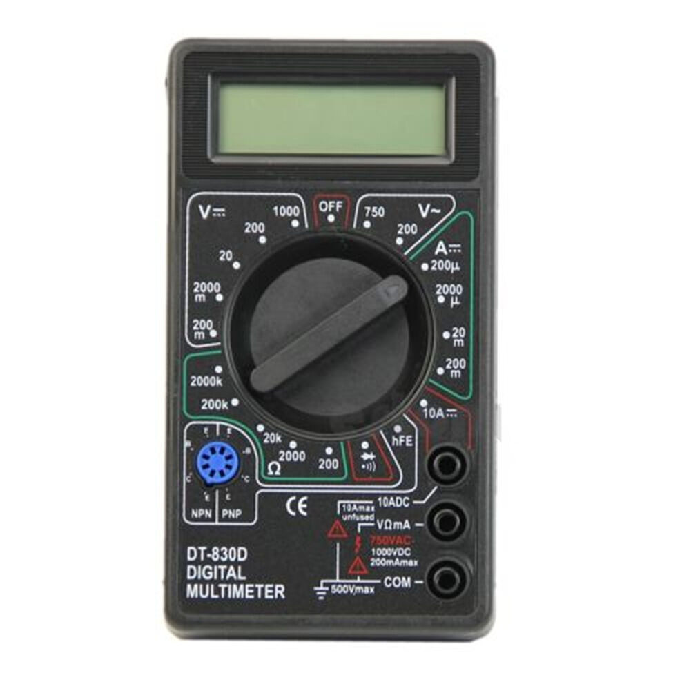
At £2.30 a pop, you can’t go far wrong (quality not withstanding, I wouldn’t suggest using this in a production device, or anywhere that high energy circuits are involved)… but you do get all this…
…for your money.
I think I may have one of those ![]()
What I’m trying to measure actually is a bit tricky, its the current going through a 40w CO2 laser tube.
The tube operates at around 15kV, but the other end of the tube is connected to earth / 0V / GND (it really is connected to the chassis which is connected to mains earth, and there is additional earthing to a dedicated earth spike)
What i have seem done in other cases is to connect a 30mA moving coil meter into the earth side of the circuit. And I bought a moving coil meter from eBay.
However I was hoping to build something like a Hall effect current sensor, to provide some better electrical isolation.
I also thought the meter I bought from eBay would contain an STM8 not an unknown chip.
Just to complicate things, the laser operates in PWM at 20kHz to control its power.
Im not even sure how accurate a moving coil meter is when given 20kHz square waves, i.e whether the coil manages to integrate the current, or whether it does what normal coils do, and are high impedance.
I guess the best way to test the 20kHz PWM issues on a moving coil meter, would be to use our beloved STM32 to generate PWM at 20kHz and drive the meter via a suitable resistor, and compare the actual current with the displayed current.
Just to complicate things, I know the tube is supposed to operate at 20mA max sustained current, but I don’t know whether thats 20mA RMS of the square wave, or 20mA if someone how the tube was running from a linear PSU rather than a PWM switch mode supply.
There is also an intersting youtube video where someone measures the voltage in their laser tube ( in a rather cavalier way), which I will find and post here ![]()
There is also an intersting youtube video where someone measures the voltage in their laser tube ( in a rather cavalier way), which I will find and post here ![]()
They work great. Except one time I did get a shocker. The meter wasn’t reading correct. I used a multimeter to see what was going on. I found out, the hard way. Next thing I know POW and the meter flew across the room and both my arms were sore. The meter circuit lost it’s ground so the whole thing floated up to several Kv and popped me. These weren’t anything to mess with either. They were used for Ion Pumps, which the transformer weighed about 25lbs. I worked on hundreds of those things. But worked on a lot worse.
Of course that was around 1988 so forgive me. lol Best I can remember there were back to back diodes tied to ground and the 2 inputs of an op amp across that. Of course with adjustment for the gain etc. I think we used 1N914 diodes or 1N4148. I haven’t retried that setup since. At one time I had a copy of the whole circuit but lost it many moves ago.
…
What I’m trying to measure actually is a bit tricky, its the current going through a 40w CO2 laser tube.
…
Just to complicate things, I know the tube is supposed to operate at 20mA max sustained current, but I don’t know whether thats 20mA RMS of the square wave, or 20mA if someone how the tube was running from a linear PSU rather than a PWM switch mode supply.
BEWARE. If the resistor becomes disconnected on either side, the open circuit will be high voltage!
Mechanical meter vs. duty cycle of pulsed signal… you could feed a PWM signal to the meter and create a look-up table of meter indication vs. pulse duty cycle %. Probably non-linear.
I found that video..
https://www.youtube.com/watch?v=Qz6J4Rs7VCw
Its one of your countrymen Andy ![]()
BTW. I have current clamp. So will give that a quick try, as it only involves pulling a wire out a bit so I can put the clamp around it.
But its not at all accurate at low currents, and as this is PWM, goodness knows what it will read ![]()
Edit.
See
The meter circuit lost it’s ground so the whole thing floated up to several Kv and popped me.

