Some preliminary results are available here..
https://github.com/pingumacpenguin/STM3 … ontruction
My take on the Scope Sketch is here..
https://github.com/pingumacpenguin/STM32-O-Scope
Its a fun little project and well worth building just for the entertainment value. Currently bandwidth is a little limited, but with a little extra effort it would be possible to make a fully functional 2MHz Scope for next to nothing. Ideal for probing i2c, audio and other low speed signals.
EDIT: We managed to squeeze the maximum speed out of the ADC, read further through the thread for details. The github code includes all of the enhancements made of the course of this thread.
I own a DSO nano (also STM32 powered) with benq firmware and the tools is really useful (I use it for audio data).
It would be interesting if there is a possibility to get 2 (or more) channels out of it (with half speed or so).
Your implementation and enhancements surely takes the idea into the usable category!
Thanks.
Ray
I own a DSO nano (also STM32 powered) with benq firmware and the tools is really useful (I use it for audio data).
It would be interesting if there is a possibility to get 2 (or more) channels out of it (with half speed or so).
Code now reads…
  const adc_dev *dev = PIN_MAP[analogInPin].adc_device;

int pinMapPB0 = PIN_MAP[analogInPin].adc_channel;

adc_set_sample_rate(dev, ADC_SMPR_13_5);
for (uint16_t j = 0; j <= maxSamples - 1 ; j++ )
{
dataPoints[j] = adc_read(dev, pinMapPB0);
}
const adc_dev *dev = PIN_MAP[analogInPin].adc_device;

int pinMapPB0 = PIN_MAP[analogInPin].adc_channel;

adc_set_sample_rate(dev, ADC_SMPR_13_5);

adc_reg_map *regs = dev->regs;

adc_set_reg_seqlen(dev, 1);

regs->SQR3 = pinMapPB0;
for (uint16_t j = 0; j <= maxSamples ; j++ )
{
regs->CR2 |= ADC_CR2_SWSTART;
while (!(regs->SR & ADC_SR_EOC))
;
dataPoints[j]=(regs->DR & ADC_DR_DATA);
}
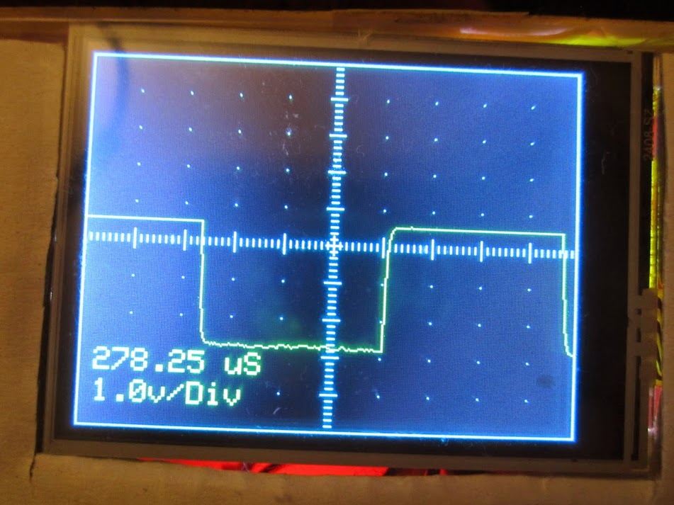
We see more artifacts on the signal, but it is still usable and with a sample now taking 1.919270833 microseconds, we are getting pretty close to the theoretical minimum ADC conversion time. This gives us 521,031.207598372 samples per second, for a bandwidth of 260,515.603799186 Hz (i.e. just over 260.5 kHz) which ‘aint bad.
The signal could be cleaned up slightly by using a proper scope probe and adjusting its trimmer. I’ll give that a shot tomorrow. The lack of a separate ADC ground plane and clean ADC Vref on these little boards is noticeable at this kind of frequency. Also the volts per division is out, not sure if that is due to attenuation due to the higher frequency or problems with my code.
If you want to learn a little bit about scope probes and high frequency signals take a look here..
https://www.dfad.com.au/links/THE%20SEC … 0OCt09.pdf
I’m happy with that. If I get a bit of spare time, I may look at using the ADC with DMA – but if anybody else wants to take a crack at beating 1.9 uS per conversion *with* DMA and an interrupt service routine, the gauntlet has been thrown. ![]()
The updated sketch is on github. https://github.com/pingumacpenguin/STM32-O-Scope
Simply type s <enter> on the Serial Console and it fires back the data points.
Paste these into a csv file and feed it to gnuplot.
gnuplut> plot ‘serial.csv’
We can zoom in…
gnuplot> plot [500:2000] ‘serial.csv’ with lines
.. you get the idea…
My initial idea was to just provide a low-cost teaching aid, but the current implementation is well beyond that! Great work.
Ray
The two plots can be found here. https://github.com/pingumacpenguin/STM3 … g-the-data
You can draw your own conclusions.
Very nice project! Obviously, this is not your first time out on the town
Ray
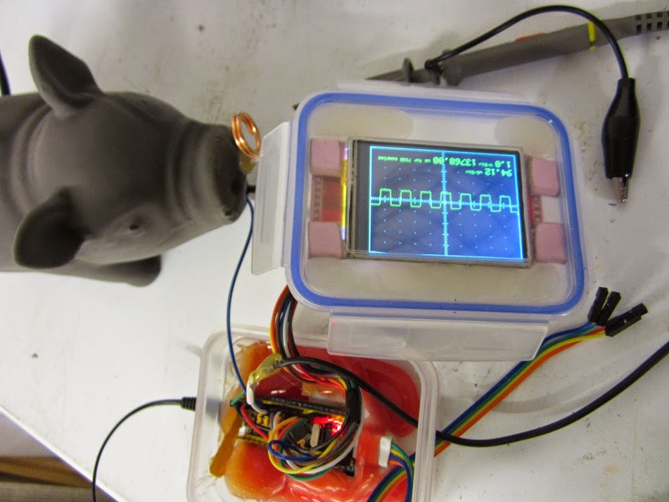
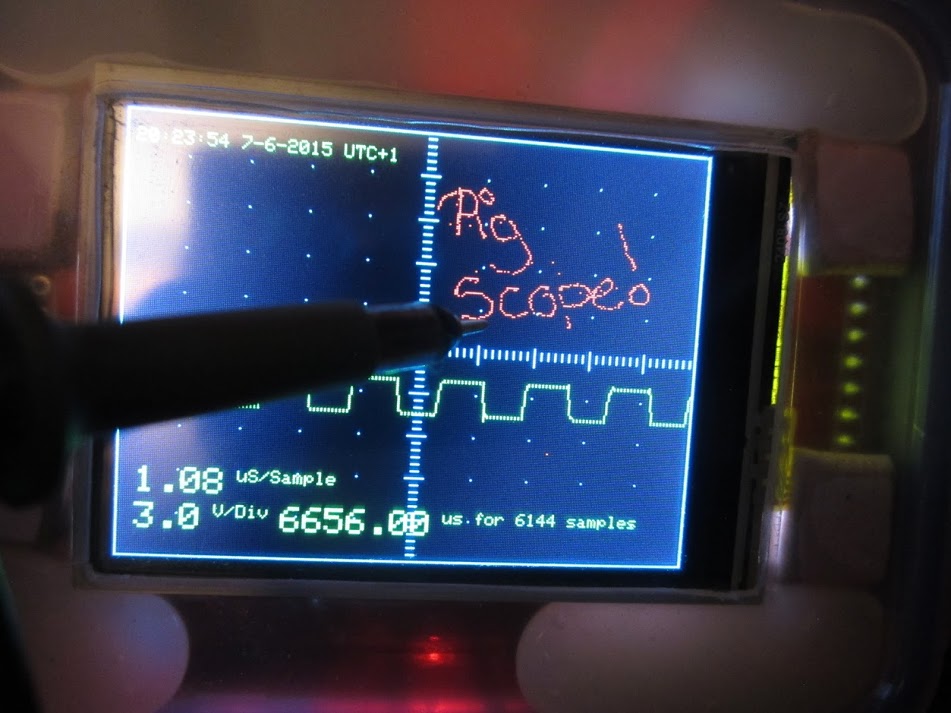
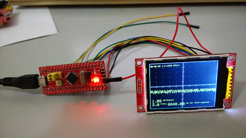
A quick visit to “Pounstretchers” to get the “food container as a project box” [http://chdk.setepontos.com/index.php?topic=10284.0] that a lot of one off projects wind up in provided something much more amusing. A £1.99 “squeaky pig dog toy”.. OK it doubled my project box budget, but I hope the results are worth it.

Mr Pig is going to have a window in his side (after some minor surgery), and all of the gubbins below is going to wind up in his ample belly with just a USB lead to connect him to the laptop and eventually a couple of LiPo batteries will be added, since our porcine friend has plenty of spare girth to accommodate them.
(Hot snot fest and big mess O’ wires)
As well as being an obvious reference to Mr Lears nonsense, the ring in the end of his nose will be the square wave test point. Initial build photos start here.. https://plus.google.com/u/0/photos?pid= … 4282217370
Porkbelly politics has nothing on this techno porker.
Too funny. I needed a good laugh, this was perfect.
Ray
Ahull I think you should look at adding DMA for the capture. You can set a timer to trigger each DMA transfer, so you can precisely set the capture frequency with the TIMER, trigger the transfer, then dump the data to the screen.
I am wasting most of my time with the bootloader the usb enumeration stuff, but if I get a minute I’ll try to see if I can test ADC DMA captures.
If that worked fine, all you would need would be 2 buttons or a touch screen to adjust the capture frequency
I must admit I’m quite enjoying messing about with this, what actually sparked my interest in the STM32F103 was the built in RTC, but that has taken a back seat for the time being, and this little project has taken over.
One thing I did discover is that the PWM frequency is actually not 1100 Hz as stated by Leaflabs, but actually 550 Hz – on the PWM pin I am using, seems the pre-scaler value they used for timer 3 is out (I’m using PB1 for my test output pin).
It was pretty obvious something was wrong, when I looked at it on the STM32-O-Scope screen, and when I compared the results on my office scope it showed the STM32-O-Scope was measuring the period correctly. I though I had a bug in my code. I then checked and there is some info about this on the leaflabs forum. I’m going to mess with the timers next if I get a chance, and see if I can set up some control over the output frequency using serial port commands.
I’ve pushed my latest code to git if anybody else wants to play. ![]()
I am wasting most of my time with the bootloader the usb enumeration stuff, but if I get a minute I’ll try to see if I can test ADC DMA captures.
If that worked fine, all you would need would be 2 buttons or a touch screen to adjust the capture frequency
I have a bunch of serial commands configured, including one to increase/decrease the timebase, so I can just hook in to those.
I have a touch screen, but I haven’t started to play with the touch library yet.
2.2.1 Description
The dual fast interleaved ADC mode is intended for the conversion of one channel. ADC1
and ADC2 convert the selected channel alternately with a period of 7 ADC clock cycles.
This means that the channel is converted every 7 clock cycles. Each ADC converts the
channel every 14 ADC clock cycles. With a 14 MHz ADC clock, it is thus possible to reach
2 Msamples per second: 14 MHz/7 = 2 MHz (sampling frequency). The conversion can be
started by external trigger or by software and the conversion results of ADC1 and ADC2 are
stored into ADC1 data register (32-bit format)
If we can manage this little trick plus DMA and timer tick based timebase, we are 99% of the way to a “real” oscilloscope. We would still need some method of calibration and there may be issues with input impedance affecting the simplistic 1 Meg Ohm resistor as attenuator approach I have adopted… but I’m sure we can fix that in software ![]()
Ahull: I believe you have taken a look on the DSO nano schematics? Maybe there a few things which can be interesting for this project…
With the DSO Nano they face the same bandwidth limitation of the ADC, and as well as buffering the input, they have squared up the input out their probes with a couple of on board trimmer capacitors (these do the job of the trimmer on a standard scope probe).
The minimalist approach I have had to adopt actually works almost as well, but runs a slight risk of zapping the ADC as there is no real input protection except for the 1 Meg Ohm resistor. Having said that, if you do blow the thing up, well the STM32 board is cheap and easily replaceable.
I was surprised how good the results were to be honest, I was expecting it to be pretty useless.
YES ![]()
Now, this is my personal approach to engineering!
Ray
YES ![]()
Now, this is my personal approach to engineering!
Ray
uint16 timer_set_period(HardwareTimer timer, uint32 microseconds) {

if (!microseconds) {

timer.setPrescaleFactor(1);

timer.setOverflow(1);

return timer.getOverflow();

}
uint32 cycles = microseconds * (72000000 / 1000000); // 72 cycles per microsecond
uint16 ps = (uint16)((cycles >> 16) + 1);
timer.setPrescaleFactor(ps);
timer.setOverflow((cycles / ps) - 1 );
return timer.getOverflow();
}
Looks like I need to trim the capacitance of my crude 1M Ohm attenuator, a few pF here, a 22pf trimmer there.. I’m sure I can square that waveform back up. ![]()
gnuplot code..
gnuplot> # Gnuplot script file for plotting data in file "serial3.csv"
gnuplot> # This file is called serial3.gplot
gnuplot> set autoscale # scale axes automatically
gnuplot> unset log # remove any log-scaling
gnuplot> unset label # remove any previous labels
gnuplot> set xtic auto # set xtics automatically
gnuplot> set ytic auto # set ytics automatically
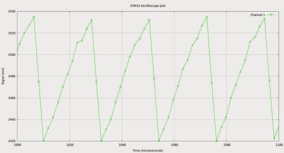
gnuplot> set title "STM32 Oscilloscope plot"
gnuplot> set xlabel "Time (microseconds)"
gnuplot> set ylabel "Signal (mV)"
gnuplot> set linestyle 2 linetype rgb "green"
gnuplot> plot "serial3.dat" using 1:2 title 'Channel 1' with lines linetype 2
gnuplot> plot [1000:1100] "serial3.dat" using 1:2 title 'Channel 1' with linespoints linetype 2
Anyway, I will give at shot after work, and see if I can write the modifications to your sketch. Given that the ADC is not too fast, I dont think there will be a big improvement by using DMA in a single channel, but with DMA we can use the interleaved mode with ADC2 and double the bandwidth, and from the datasheet I understand DMA is a requirement to be able to use the interleaved mode:
11.8 DMA request
Since converted regular channels value are stored in a unique data register, it is necessary
to use DMA for conversion of more than one regular channel. This avoids the loss of data
already stored in the ADC_DR register.
Only the end of conversion of a regular channel generates a DMA request, which allows the
transfer of its converted data from the ADC_DR register to the destination location selected
by the user.
Note: Only ADC1 and ADC3 have this DMA capability. ADC2-converted data can be transferred in
dual ADC mode using DMA thanks to master ADC1.
So I will need to add an ISR, change a couple of bits in CR2, and set the DMA controller, pretty similar to what we did with SPI.
Once that works, I will look at enabling the interleaved mode.
So if that is the case we can point the DMA to our ADC array, say give me ‘n’ conversions in that chunk of memory (our array), then examine them later once the hard work is done. This leaves the processor free to do other things, like draw the display, read the touch panel, talk to the serial port or whatever.
I’ll be pretty impressed if we can manage this little trick. BTW I am not wedded to any particular pin for the ADC input, if we need to shift to another pin, because of conflicts with timers or whatever, I’m fine with that.
The DMA has multiple modes of operation, you can give it a fixed length buffer but you can also operate it in circular buffer mode, though I don’t know if that applies to ADC (probably).
With a scope, it would probably mean you grab the data into a buffer a bit quicker and easier than looping and waiting.
At the moment Victors SPI DMA code is “blocking”, i.e while its transferring e.g to the display, the code sits in a while loop and waits for completion.
However, I’m pretty sure that its possible to get the DMA to trigger an interrupt when its finished, so it would be possible to build a output frame buffer, and then kick off the SPI DMA to write it to the display, and then go back to sampling the ADC on the main loop
Its really a job for DMA, as you can transfer from ADC to memory at the same time as transferring a frame buffer to the display, and still have the main loop running your gui control code.
Although you could write this using RTOS it won’t give you the true multitasking that DMA gives you. i.e DMA gives the effect of having a multi core processor – as long as some cores are just transferring data.
RTOS would have to constantly context switch to do the same thing, which would be incredibly inefficient.
First declare this at the beginning:
// End of DMA indication

volatile static bool dma1_ch1_Active;
Once we have it working, I suspect the next move is to create an ADC lib similar to the SPI lib in order to make the code modular, and easier to port to the other architectures (F4 etc).
STM32-O-Scope.ino: In function 'void takeSamples()':

STM32-O-Scope.ino:385:3: error: 'regs' was not declared in this scope

'regs' was not declared in this scope
regs is declared on the first part of that function, in this line:
adc_reg_map *regs = dev->regs;
void takeSamples ()

{

/*

for (uint16_t j = 0; j <= 10 ; j++ )

{

analogRead(analogInPin);

}

*/

// In effect I have unwrapped analogRead() into its component parts here to speed things up.

// this avoids the need to check the pinmap every time we go round the loop.

const adc_dev *dev = PIN_MAP[analogInPin].adc_device;

int pinMapPB0 = PIN_MAP[analogInPin].adc_channel;

adc_set_sample_rate(dev, ADC_SMPR_1_5);

adc_reg_map *regs = dev->regs;

adc_set_reg_seqlen(dev, 1);

regs->SQR3 = pinMapPB0;

/*

// Discard the first 10 samples to allow the ADC to stabalise.

for (int16_t j = -10; j <-0 ; j++)

{

regs->CR2 |= ADC_CR2_SWSTART;

while (!(regs->SR & ADC_SR_EOC))

;

if (j > 0)

{

regs->DR & ADC_DR_DATA;

}

}

*/

/*

for (int16_t j = 0; j <= maxSamples  ; j++ )

{

regs->CR2 |= ADC_CR2_SWSTART;

while (!(regs->SR & ADC_SR_EOC))

;

if (j > 0)

{

dataPoints[j] = (regs->DR & ADC_DR_DATA);

}

// TODO: Tighten up this loop or better still use DMA and/or dual conversion to get up to 2MS/s i.e. 0.5uS per sample and sub-microsecond accuracy.
// sweepDelay adds delay factor with a sub microsecond resolution we would of course be better using an ISR and DMA for the ADC

//

//sweepDelay(sweepDelayFactor);

}

*/

// Loop above replaced with this DMA transfer setup:

regs->CR2 |= ADC_CR2_CONT; // Set continuous mode

dma_init(DMA1);

dma_attach_interrupt(DMA1, DMA_CH1, DMA1_CH1_Event);

adc_dma_enable(ADC1);

dma_setup_transfer(DMA1, DMA_CH1, &ADC1->regs->DR, DMA_SIZE_32BITS,

&dataPoints, DMA_SIZE_16BITS, (DMA_MINC_MODE | DMA_TRNS_CMPLT));// Receive buffer DMA

dma_set_num_transfers(DMA1, DMA_CH3, maxSamples);

dma1_ch1_Active = 1;

dma_enable(DMA1, DMA_CH1); // Enable the channel and start the transfer.

regs->CR2 |= ADC_CR2_SWSTART;

while (dma1_ch1_Active);

dma_disable(DMA1, DMA_CH1); //End of trasfer, disable DMA

regs->CR2 &= ~ADC_CR2_CONT; //and Continuous mode.

}
I’ll have a play with this tomorrow. Thanks.
This is the capture section to include in your take function:
  regs->CR2 |= ADC_CR2_CONT; // | ADC_CR2_DMA; // Set continuous mode and DMA

dma_init(DMA1);

dma_attach_interrupt(DMA1, DMA_CH1, DMA1_CH1_Event);
adc_dma_enable(dev);
dma_setup_transfer(DMA1, DMA_CH1, ®s->DR, DMA_SIZE_32BITS,
&dataPoints, DMA_SIZE_16BITS, (DMA_MINC_MODE | DMA_TRNS_CMPLT));// Receive buffer DMA
dma_set_num_transfers(DMA1, DMA_CH1, maxSamples);
dma1_ch1_Active = 1;
dma_enable(DMA1, DMA_CH1); // Enable the channel and start the transfer.
samplingTime = micros();
regs->CR2 |= ADC_CR2_SWSTART;
while (dma1_ch1_Active);
samplingTime = (micros() - samplingTime);
/* uint32_t t0 = millis();
while (dma1_ch1_Active) {
if ((millis() - t0) > 100) {
dma1_ch3_Active = 0;
break;
}
}
*/
// regs->CR2 &= ~ADC_CR2_DMA;
dma_disable(DMA1, DMA_CH1); //End of trasfer, disable DMA and Continuous mode.
regs->CR2 &= ~ADC_CR2_CONT;
This is what’s needed for interleaved mode:
First change the array declaration so we can access it as a single 32 bit word during capture:
uint32_t dataPoints32[maxSamples/2];

uint16_t *dataPoints = (uint16_t *)&dataPoints32;
We have a couple of issues, and some pre-existing bugs, but over all that is a vast improvement.
The triggering certainly needs re-visited, my current method is crude to say the least. It was born out of necessity rather than carefully crafted.
Also the scaling and drawing of the waveform is currently pretty poor. I need to make that slicker. Anything that improves drawing speed to the display would also be a benefit.
I’ll push what we have done so far to git and you can compare with your working copy to make sure I picked up all of your changes. If you want commit access to my git repo, PM me your public key and I will add you.
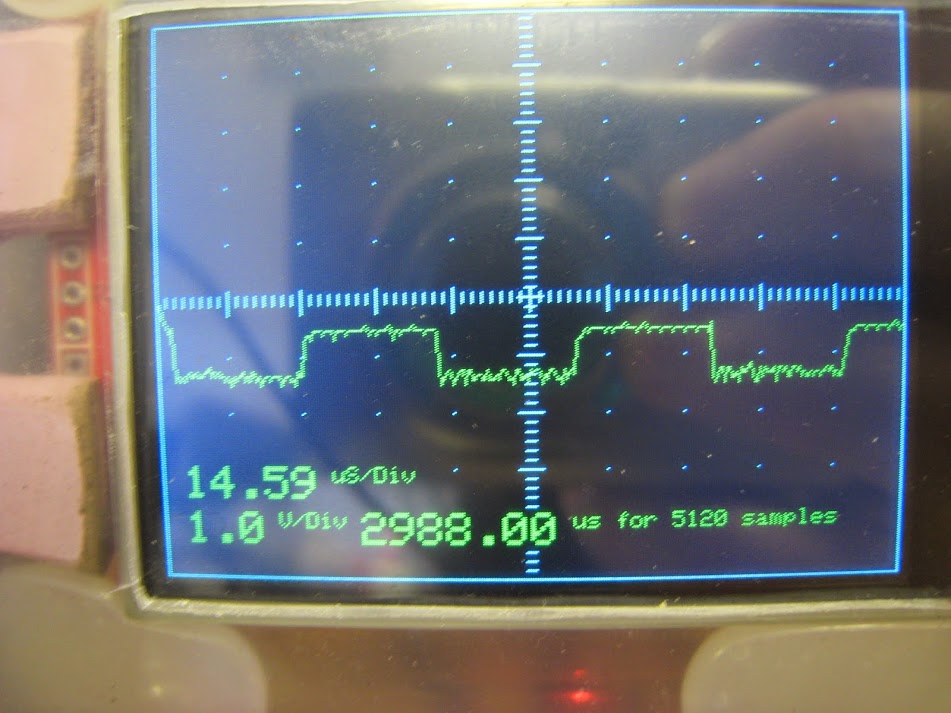
NOTE: uS per div is misleading, this should be the time per screen division, but currently I think it relates to the time per sample.
EDIT: What was odd was that that this figure is wrong. The total time taken for the samples is 2988.0 uS and the number of samples is 5120 so this gives a per sample time of 0.58359 uS per sample .. in other words we are seeing an issue here when we divide ints and the result is <1
I have corrected this and it gives a per sample time of 0.58uS which gives a figure of 1.713 Mega Samples per Second. This is pretty close to our minimum of 0.5us or 2 megasamples per second.
Quite why we end up with such a wildly incorrect answer when we divided our ints is another question.
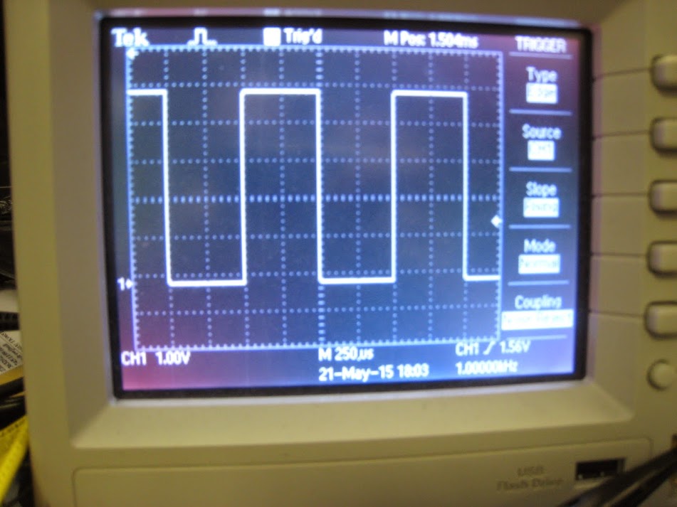
The same 1kHz reference signal viewed simultaneously on my Tektronix.
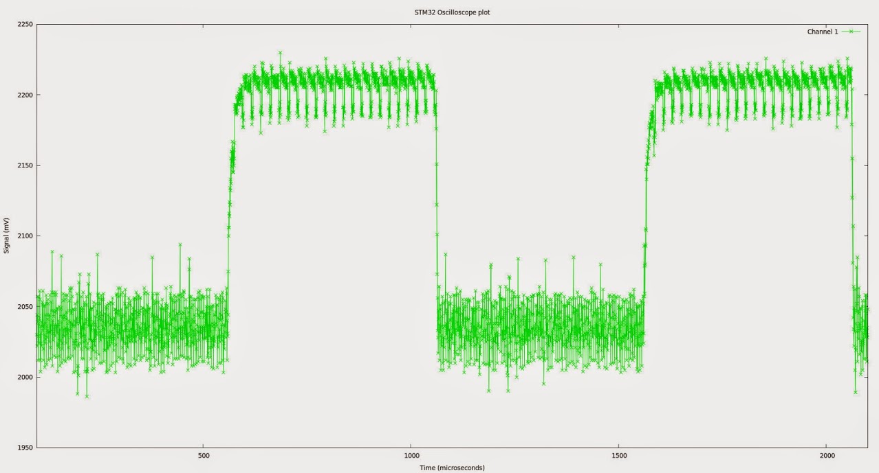
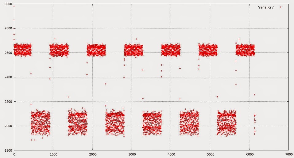
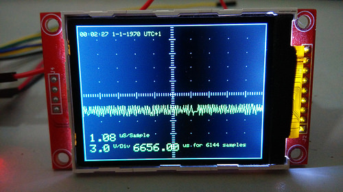
An area of the data – plotted with gnuplot. You can see there is a fair amount of noise, but I suspect a lot of that comes from inadequate smoothing on the STM32F103 board. Additional caps across the ADC vref will probably eliminate a lot of this. Sample rate is 1.5 clock cycles per sample ( ADC_SMPR_1_5, /**< 1.5 ADC cycles */)
BTW if anybody is looking for a signal function generator, asearch ebay for AD9850 – These little boards are quite useful – in fact I can see another little project coming up. The STM32-Function Generator.
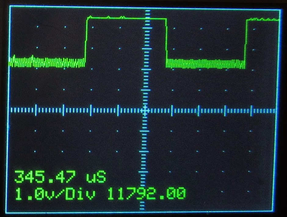
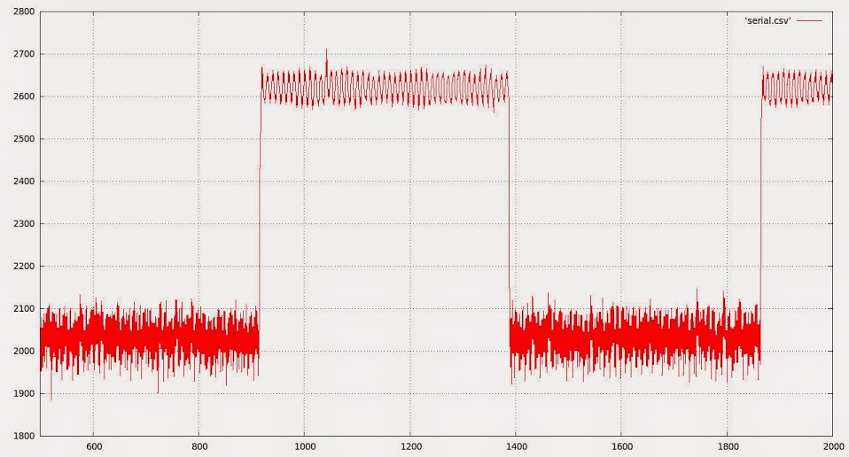
Much better, although there is a noticeable 50 kHz or so square wave ripple on the signal.
If not on your board, a small inductor in the Vcc line to the Analog portion of the chip is also helpful. Original boards were 4 layers with an analog ground plane but my clone Maple Mini is a 2-sided rehash of the layout; somewhat inferior in design, but at $4 one has to be realistic about fabrication.
Good job. The beast is evolving into a very inexpensive, low-budget home-built tool for the weekend experimenter.
Ray
Besides that, both ADC1 and ADC2 have a calibration function, which I believe is called upon initialization of the ports, but I am not certain, could be good to call it at some point in the sketch.
Then we have the single PSU issue. I am using a mini clone, and your pictures show another board that probably doesn’t have a separate PSU either.
As a test before going to sleep I trimmer the last 4 bits of the samples, leaving only 8 bits of resolution, plus I should have been trimming the 4 top bits as the capture is only for 12 bits, and I wasn’t so we should do that, that may reduce that noise too.
So in my list:
-Trim top 4 bits.
-Use different pin.
-Call calibration on both ports at start.
-Trigger ADC continuous capture a bit earlier.
Now, the ADC sample time can be adjusted on the fly. Would be a good idea if you could add a command to change that, so for slower signals we get a cleaner capture.
BTW, according to specs, when using 72Mhz on the MCU main clock, the fastest ADC capture time is 1.17 uS. As we use 2 ADCs we could get double the captures, so .58 uS, which is the times you say above that you get maximum. I think we have reached the speed limit of the chip, now all we can do is improve accuracy.
Use this loop after the ADC DMA finishes to trim the top 4 bits that don’t belong to the actual sample, may make a difference. I don’t have a real oscilloscope to compare ![]()
...

dma_disable(DMA1, DMA_CH1); //End of trasfer, disable DMA and Continuous mode.

//  regs->CR2 &= ~ADC_CR2_CONT;

for (int16_t j = 0; j < maxSamples/2  ; j++ )

{

dataPoints32[j] &=0x0FFF0FFF;

}
Try trimming the 2 or 4 bottom bits of the samples with 0FF60FF6 or 0FF00FF0.
That will reduce noise for sure at the cost of losing some resolution.
Now, I remember reading an STM application note on how to increase an ADC capture resolution by using the noise in it.
I’ll have to find it and see if we can apply it to this case.
I thought on Roger’s idea for a frame buffer, but that would not work for this LCD and MCU. The display has 240×320 pixels, 2 bytes each, that needs around 144KB of RAM to store a frame.
Now that would work in the smaller 128×128 displays, that need 32KB for a frame buffer, but only using a bigger MCU.
Any way we should get quite a big speed improvement by using the reworked line drawing functions, or even changing the way the signal is printed now, so it uses more of the fastHline and fastVline whenever possible.
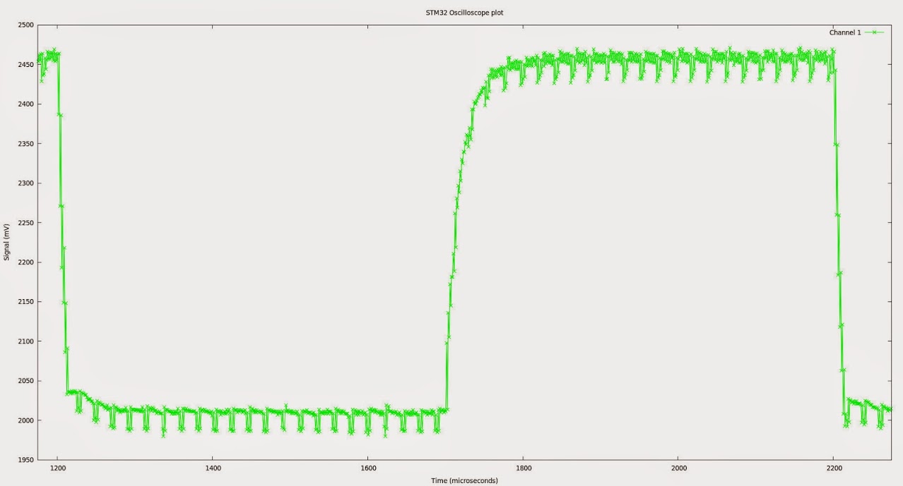
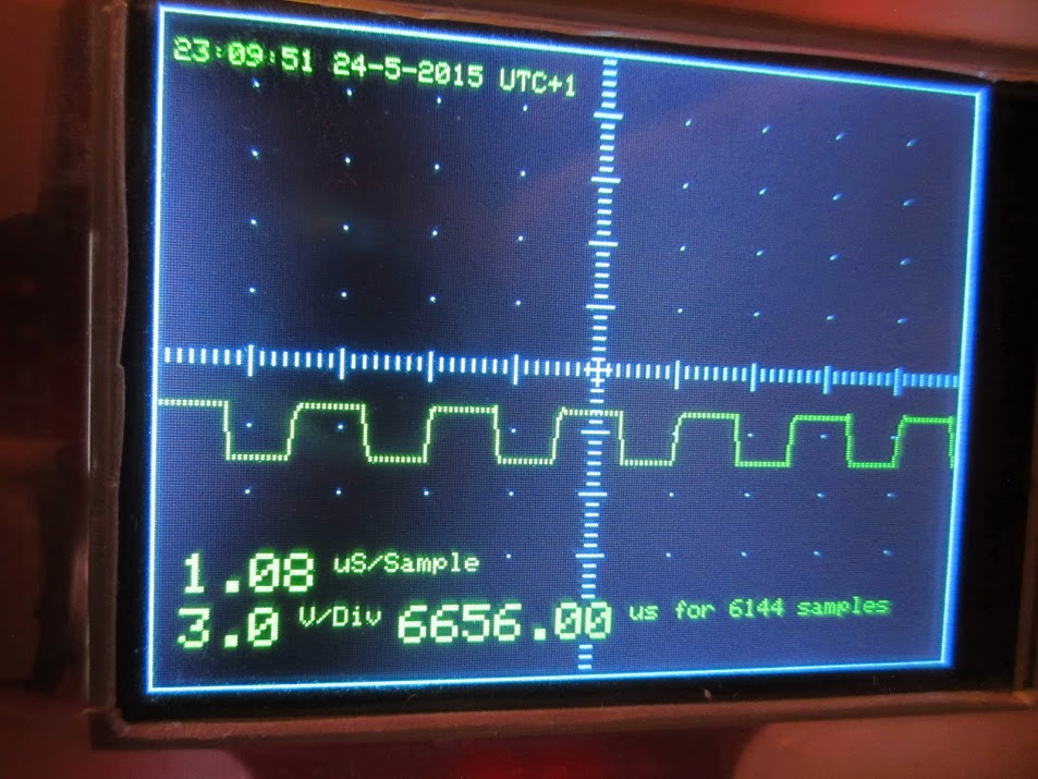
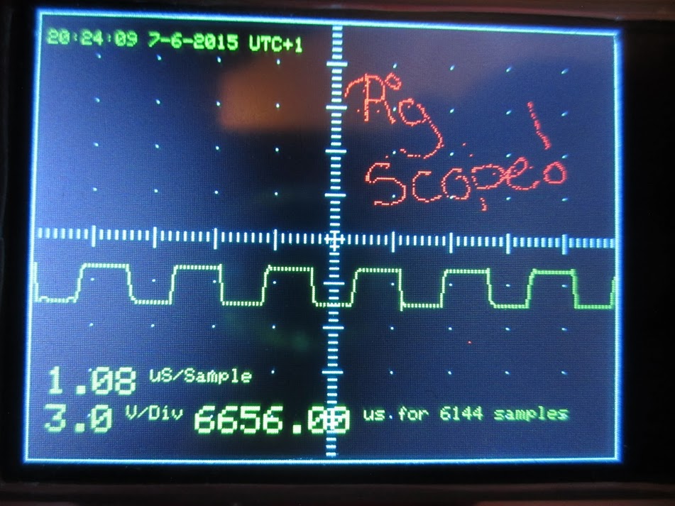
The above is with ADC ADC_SMPR_13_5 (1.08 uS per sample)- it looks a whole lot cleaner. I do need to see if I can somehow clean up the ADC supply, but that is a noticeable improvement. I’ll perhaps see if I can put the test pin on port C or whatever. The idea of having a test pin with a known frequency of squarewave still appeals, but I guess if it is going to cause issues, I may end up dropping it. Grounded shielding on the test signal cable might be all that is required.
I also need to look at adding a small capacitor in parallel with my 1 meg resistor (or some other little tweak) to trim up my probe and flatten off that annoying curve on the leading edge of the 1kHz test signal.
There seems to be a jitter between the two ADCs which I suspect we can eliminate by calibrating them.
This is pretty obvious when you look at some of the sample data on a flat spot on the waveform.
#Time, ADC, Value

7722.84 1 1997

7723.92 2 2015

7725.01 1 1997

7726.09 2 2015

7727.17 1 2001

7728.26 2 2015

7729.34 1 1996

7730.42 2 2015

7731.51 1 1997
adc_calibrate(const adc_dev *dev)
So try adding them at some point at the start of the sketch when the pulse output is not going on.
I think the libmaple code runs that on start up, but not totally sure. In any case if it doesn’t help we just need to take it out:
adc_calibrate(ADC1);
adc_calibrate(ADC2);
I guess running the calibration while the PWM output is going on may affect the calibration.
We can set a 2 channel oscilloscope rather easily the exact same way, only providing a different input to each ADC, and changing some bits in the dual mode settings, so both capture at the same time. That should provide for almost 1Mhz per channel.
One other option, for digital signals, is to do a port capture rather than ADC. That could provide 15 channels in a single IO. I believe the max may be around 50Mhz on digital inputs with DMA, but would need to check.
I changed a couple of other things.
1) I re-enabled the test pin, but dropped its frequency, and this seems to cause far less interference.
2) I am now measuring the test pin on the STM32 rather than the test signal on my real scope (because it is in the office and I am at home ![]() )
)
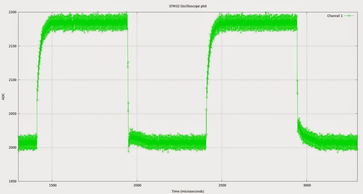
so bear in mind that although the noise appears to have increased this is due to the fact that were are looking at a 3v3 signal rather than a 5v signal.
As before the issue becomes apparent if we look at the data.
#Time(uS), ADC Number, value

7734.36 1 2194

7735.44 2 2174

7736.52 1 2196

7737.61 2 2176

7738.69 1 2195

7739.77 2 2176

7740.85 1 2197

7741.93 2 2173

7743.02 1 2197

7744.10 2 2176

7745.18 1 2193
adc_calibrate(const adc_dev *dev)
So try adding them at some point at the start of the sketch when the pulse output is not going on.
I think the libmaple code runs that on start up, but not totally sure. In any case if it doesn’t help we just need to take it out:
adc_calibrate(ADC1);
adc_calibrate(ADC2);
I guess running the calibration while the PWM output is going on may affect the calibration.
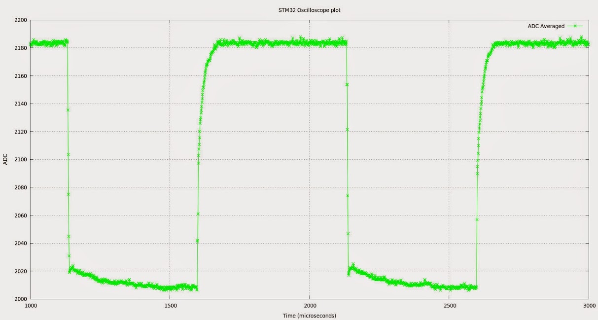
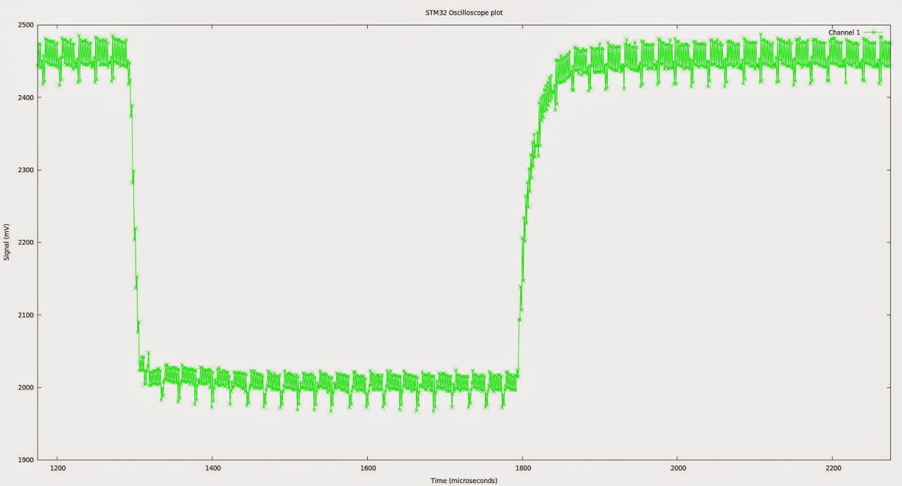
As you can see it had the effect I expected and removed the jitter. Obviously this is not the best way to eliminate the error, having the two ADCs agree would be better as it would preserve our bandwidth (averaging will have the effect of lower the bandwidth), but it shows what residual error remains once we eliminate this problem. By my metric calibrated eye, I guestimate the remaining error lies somewhere between 1% and 5% (so long as we don’t consider the slew contributed by the attenuator) which is pretty respectable. But we can do better!
EDIT: I should really fire up my analogue oscilloscope and compare, but its getting late here, so that looks like a task for tomorrow.
I thought the error was proportional, which would be more difficult to adjust, but if it is consistently that, we could try just adding 18 from the lower one, or subtracting 18 from the highest one.
About the start of the capture, we can set both ports to be in continuous mode and start capturing during the setup routine, and just start and stop the DMA transfer to memory.
And on the second bnc connector… well, up to you, but you can put a warning before posting the picture so anyone offended can just avoid it ![]() otherwise I don’t think the silicone pig will care much where you drill an extra hole, he may squeal a little though…
otherwise I don’t think the silicone pig will care much where you drill an extra hole, he may squeal a little though… ![]()
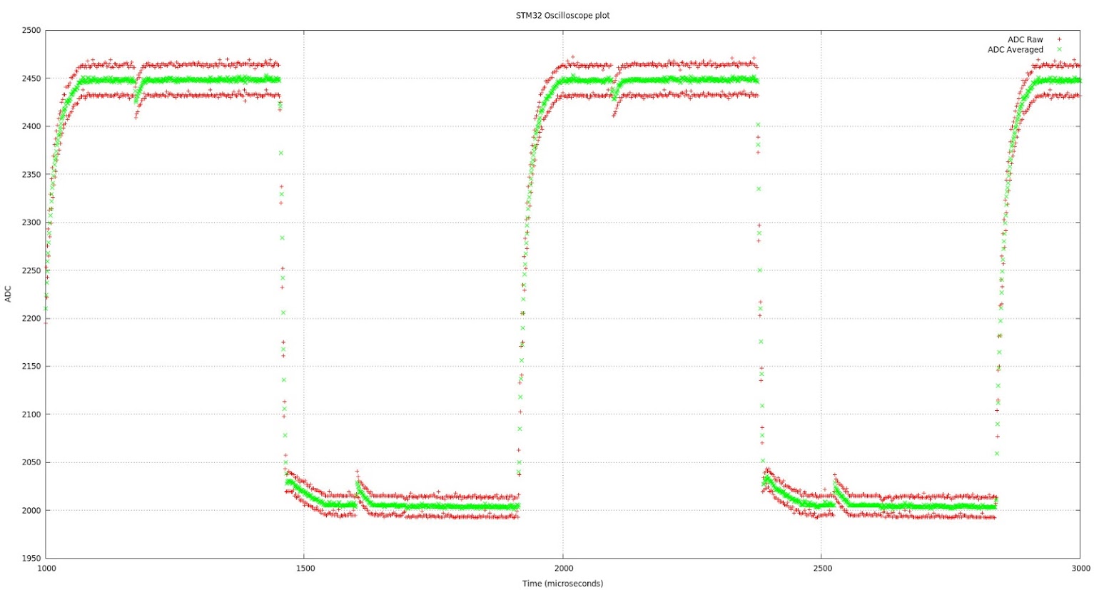
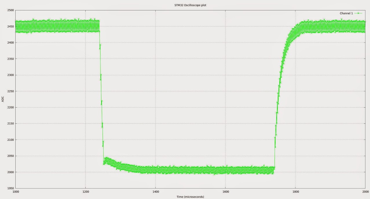
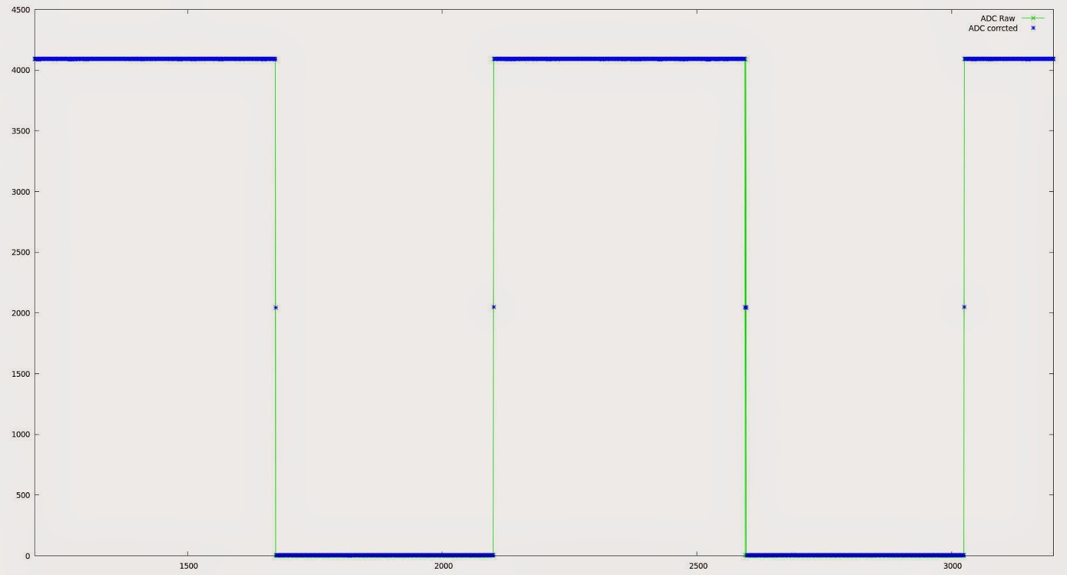
Red line is a plot of the raw ADC points, Green is the same data + half the difference between this point and the last.
NOTE: The difference swaps between positive and negative at each point, in case you were trying to figure out why it is always added.
i.e. I am taking the difference between 45 and 50 to be +5 but the difference between 50 and 45 to be -5
I think the difference factor should be weighted over more than 2 conversions, otherwise it will have a disproportional effect on fast transients.
Can anybody think of a better way to do this?
Bear in mind that the “difference” changes, it is not a fixed figure, so it can vary over the length of our sample buffer, presumably due to the separate sources of errors in both ADCs
Here is a closer view of the error
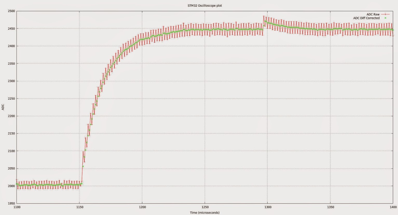
Can anybody think of a better way to do this?
Just my opinion, the “smoothing factor” should be user programmable… that is, a pushbutton held during power-on would run a small routine to capture the user input over Serialx. and this would be written to flash. Then during normal bootup, if the set-up button is not low at startup, the flash is read for configuration.
This way, as you get into soft-settings, the menu can be expanded easily and the procedure can be menu driven numerically.
Ray
One other thing to note. That irritating glitch in the previous graphs is crosstalk from my test pin. If I switch it on, I see the glitch. Switch it off… gone…. I need to find a better pin for this.
The USB peripheral is slightly different than the rest from what I saw in the datasheet, but I think it is worth testing something like that in the ADC.
I’ll give it a shot if I have a moment later, I want to test Ray’s RTC first.
I worked some optimizations in the lcd library. It is still not the best it can, but much faster than before specially when it comes to drawing the captured data.
Download the zip attached and use that. It requires the latest SPI library from Roger’s repo.
- Adafruit_ILI9341_STM.zip
- (6.41 KiB) Downloaded 125 times
BTW I added Real Time Clock functionality to the Scope. See the RTC library page for more details.
If you want to set the clock from a Linux host, the following one-liner should to the trick (assuming your serial port is on /dev/ttyACM3 , it is writeable by your user, and the serial monitor is not already running on it).
NOWTIME="timestamp $(date --date "+1hour1seconds" +"%s")";echo -e "$NOWTIME\r" >/dev/ttyACM3
I cleaned up the code for the libraries a bit more, so they don’t print artifacts if the sketch tries to draw a line out of range.
You will see that as some stray green dots depending on the input wave, specially with noise (just putting my finger on it).
You can download the latest version from here:
https://github.com/victorpv/Arduino_STM … LI9341_STM
I sent a pull to Roger, so it should be updated in his repo soon, as the previous one does not compile anymore after the SPI library has been updated.
Job well done… this should be a required build for any serious tinkerer who does not have access to a scope. This would be a great PSoC 4200 project due to the “free” analog subsystem and analog mux + OpAmp. FYI, only $4 http://www.cypress.com/?rID=92146
( do not even consider 4100 )
Ray
The following picture is the output from this “scope”, with PB0 jumpered to PB1 (i.e. test out to analog in with no test probe). I promise I haven’t faked this… it looks like the squarest square wave I have ever seen.
So with a little work on the probe, we should get some pretty clean results, so long as we can keep the interference and reflections down.
Hehehehe…. and all for under $10. Very nice. (Pig carcass extra, batteries not included!)
Ray

- FlyingScope.jpg (12.7 KiB) Viewed 2453 times
The following picture is the output from this “scope”, with PB0 jumpered to PB1 (i.e. test out to analog in with no test probe). I promise I haven’t faked this… it looks like the squarest square wave I have ever seen.
So with a little work on the probe, we should get some pretty clean results, so long as we can keep the interference and reflections down.
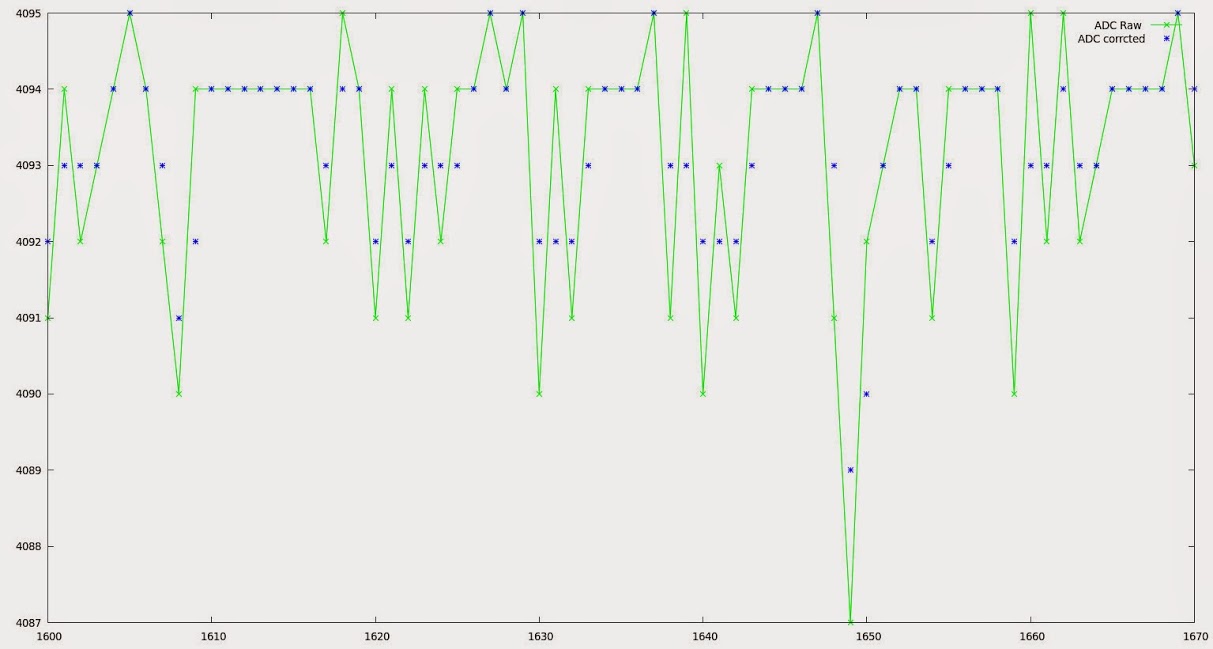
As you can see the two ADCs agree within a very close margin in this sample, 8 parts in 4096 or around 0.195% which if it is typical is pretty impressive.
EDIT: To put that in context, for our 3.3V signal we are measuring to something around +/- 0.0064 V or 6.5mV. all this without any additional amplifier or buffer. Not quite good enough for an EEG which requires around 0.5uV resolution perhaps, but still very useful precision.
I had separated the ADC setup code from the takeSample routine, but did not push that up, and was before you added the RTC code.
I will try to download your latest, take the ADC setup to a new routine again, and then push right away before you add some new feature ![]()
I was thinking on turning this into a CoOS or FreeRTOS sketch, mostly for demonstration purposes on what the RTOS can do, and get more experience with them. I think CoOS results in a really small Flash and RAM footprint and makes coordinating tasks pretty easy, but not sure the PigScope will benefit from it. Were you thinking on adding any new functionality to it that could benefit from an RTOS?
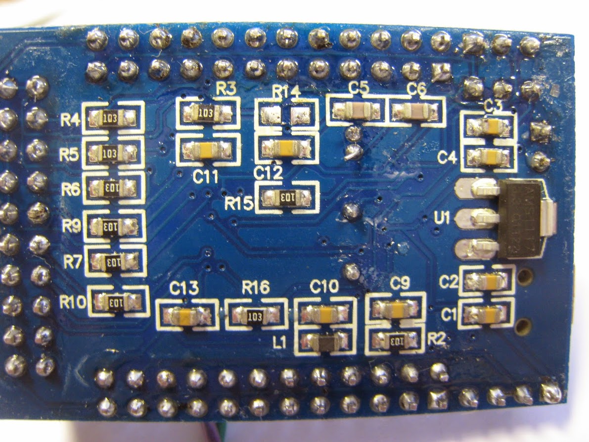
BTW, the ugly board makes a great low noise oscilloscope if nothing else…
But a voltage follower might be of use here..
I see from the wave forms the effects of a two sided PCB and the combination of an impedance mismatch between the probe and the ADC input..
A ‘Fast’ voltage follower used as an interface between the ADC input and the probe would go a long way to relieve ?some of the very obvious lack of high frequency response or the rounded leading edges of both the inputs..
I repaired all the test equipment on my last job (retired in 2008) and O’Scopes were my ‘other’ right hand..
What I see is a mismatch on the ADC input. By driving the input with a unity gain buffer or a fast Op-Amp would IMO help a great deal..
As the output impedance of a buffer or voltage follower is typically under 100 ohms and the input impedance is limited by the sampling rate of the ADC.
Just my $.02 worth..
It’s nice that there is a separate forum for this most amazing/bang for the buck board(s)…
Doc
It may be possible to passively trim the scope probe to match the impedence of the ADC and eliminate the high frequency issues, perhaps taking an attenuation hit to improve high frequency response. I haven’t done anything about this yet, so any input would be welcome.
An Active Probe approach may be the only option though, but that adds a layer of complexity and cost. I wonder what the simplest and cheapest way of doing this would be, given our low cost low bill of materials goal. An active probe would also allow us to add some level of input protection, but as I said in a previous post, blowing up the uC and/or ADC would be sad, but they only cost a couple of quid, so not the end of the world. Input protection could simply be a couple of zenners and a picofuse or a mob. but again I hadn’t given this much thought. Any protection across the input is likely to have knock on effects on the frequency response, particularly in light of the lack of buffering.
Off topic I know Doc,but you don’t know where I might find parts for an old Metrix OX 2000 scope do you. I have the carcase of one in my garage, it looks like a long term project, since it is missing the PSU, analog input card and CRT driver board. A saner individual than me would no doubt just put it in the bin. ![]()
After that I’ll try to adapt it to CoOS, but I’ll keep the function names, so if you make changes within a function before I push that up, all we need to do is copy that function straight up.
After that I’ll try to adapt it to CoOS, but I’ll keep the function names, so if you make changes within a function before I push that up, all we need to do is copy that function straight up.
‘gmtime’ was not declared in this scope
I don’t see either one of those in Paul’s time library, where should they come from?
#include <time.h>

void setup() {

// put your setup code here, to run once:
const time_t* t;

gmtime(t);

}
#include <time.h>

void setup() {

// put your setup code here, to run once:
const time_t* t;

gmtime(t);

}
does it need to be included by RTClock
Such a pun! ![]()
I’m having the same issue… just ran out of time yesterday to post about it. Wife’s to-do list is interfering with my playing.
Ray
I am using version 1.6.0 of the Arduino IDE.
Yesterday I tested installing GCC 4.9.0 15Q1, and still was getting the same errors.
I am using version 1.6.0 of the Arduino IDE.
Yesterday I tested installing GCC 4.9.0 15Q1, and still was getting the same errors.
I may be using a different version of the ILI9341 libraries. I’ll need to check once I get back from the supermarket.
Multiple libraries were found for "Adafruit_ILI9341_STM.h"

Used: /home/ahull/Arduino/libraries/Adafruit_ILI9341_STM

Not used: /home/ahull/PersonalApps/Arduino.cc/beta/arduino-nightly/hardware/Arduino_STM32/STM32F1/libraries/Adafruit_ILI9341_STM

Multiple libraries were found for "Adafruit_GFX_AS.h"

Used: /home/ahull/Arduino/libraries/Adafruit_GFX_AS

Not used: /home/ahull/PersonalApps/Arduino.cc/beta/arduino-nightly/hardware/Arduino_STM32/STM32F1/libraries/Adafruit_GFX_AS
Andy, what version of the IDE are you using?
Paul’s Time library, called Time (with uppercase T) seems to be taken for time.h from the standard library.
I get to compile by renaming Paul’s library to Time1.cpp and Time1.h.
No idea if this is specific to the Arduino IDE, or rather to gcc for Windows, or it depends on what order gcc loads each header file.
Ray
Is this a case in-sensitivity issue on windows, e.g. Time.h == time.h which is an internal header in the compiler ??
I suspect that its best not to call your own files Time.h or Time.cpp just to be safe
Ray is using Arduino 1.7.3 from “the others” while I use the 1.6.0, and I also tried gcc 4.9 with same results. So the issue seems to be that windows for whatever reason doesn’t care for the case, although with other libraries I have found that I had to match the case or it would not find the files… go figure…

Idea (c) 2015 Niall Chapman… all rights reserved. Value of bacon may go up as well as down. You sense of humour may be at risk if you do not keep up payments… etc.
Ray
I noticed that if the sketch is waiting for a trigger level to capture the next batch of samples, it seems to be hold in that loop forever until it triggers, and in the meanwhile will not respond to any other serial commands.
As soon as the trigger event happens, it goes and responds to all the commands that were sent in the meanwhile. I haven’t check the code of the trigger section to see why is that, I believe is not board specific but I had not noticed that before.
BTW I have not started turning it to an RTOS yet, if you need to make changes push them to the repo and I’ll download again before starting with RTOS.
If we can make the triggering more robust we could look at averaging schemes over multiple triggers to get better resolution (although this would require more RAM or fewer samples per event and might not be practical on the STM32F103C8XX boards). There are a couple of tricks that also allow increased bandwidth by averaging too, so we might theoretically be able to pluck a few more megasamples/sec from our short signal with a bit of smoke and mirrors. Consistent triggering is key to these ideas though.
This might make interesting reading.
Changes pushed to git for those who want to join the party.
Changes pushed to git for those who want to join the party.
Changes pushed to git for those who want to join the party.
Changes pushed to git for those who want to join the party.
I just need to find an Oink.mp3
I just need to find an Oink.mp3
Are you intending to use the same display ?
btw.what display are you currently using ?
I suspect that a parallel display using UTFT will be much better for a scope (if you are using SPI the update rate would be a bit low wouldn’t it ?)
Ps. I have a parallel display I was thinking of trying on one of my larger boards
Bt I suppose the F103C boards will struggle to have enough pins,
Ie I think my display is 16 bit address / data, plus 4 control lines
Are you intending to use the same display ?
Ok about your display. Yes. Plotting a few points, probably won’t be that much faster on parallel
Re: Parallel on C series
It has touch as well, but I suspect there won’t be enough pins for all of that on a C8 ![]()
Looking at at my Red Pill board, it doesn’t have all 16 pins on the same port broken out, (either A or B), which would impact performance, as you’d need to split stuff up, perhaps 8 bits on port A and 8 on port B, and if you had to do individual bit manipulation and not even do banks of 8 bits, the performance is likely to end up lower than using SPI ![]()
I think perhaps the parallel displays are best suited to the bigger R, V or Z series boards
I think perhaps the parallel displays are best suited to the bigger R, V or Z series boards
If nothing else I now have my very own Etch-a-sketch. ![]()
EDIT: If you want to play with this as it currently stands, I have pushed my changes to github. You will need the IDE serial monitor running to use it as an etch-a-sketch, because it spits out the co-ordinates on the serial debug as it runs, so eventually it will stop plotting if the serial monitor is not running.
For the record, I currently have these calibration values in my UTouchCD.h but once the pigscope touch calibration routine is written I’ll store over-rides in nvram.
// PIGSCOPE AGAIN

#define CAL_X 0x0388C10FUL

#define CAL_X 0x004E0D7AUL

#define CAL_S 0x000EF13FUL
But hey! Maybe this is a market niche: A DSO with on screen notepad function!
The first is frequency analysis (FFT). I intend to start with something along these lines unless someone has a better suggestion. The “Numerical Recipes in C” mentioned on that page is available here.
My Rigol scope has some excellent Measurement features, which would probably be easier to implement than FFT.
I cant remember the full list, but it does Frequency and Time measurements (assuming the waveform is periodic), and will measure the time of the low or high parts of the waveform
it also measures voltage, VRMS and peak to peak etc
I find these quite handy
you could also add cursors, e.g. measure delta T or delta V etc
http://hackaday.com/2015/07/21/fast-adc-for-laser-lab/
It seems that with a little touch of smoke and mirrors we might get circa 48MHz of squealing pig bandwidth (on repeating signals of course) out of our 1MHz ADC… potentially even 72Mhz or even higher if the STM32 variant has ADC has three or more channels.
All I need now is a little of that magic missing ingredient .. spare time to tinker… unless someone else beats me to the punchline again of course.
Even if I/we never get around to trying this, the HAD article and the writeup is well worth a read.
Trying to compile the sketch with IDE 1.6.5 on Win7 but it fails – it says the functions called from setup() and loop() haven’t been declared before they are called.
I can get around this by declaring the functions first or by moving setup() and loop() to the bottom but surely I shouldn’t have to do either.
Any ideas?
I guess you’ll need to wait until Andy (the author of the code gets back to you), he is in Scotland (UK) where its currently the middle of the night
Trying to compile the sketch with IDE 1.6.5 on Win7 but it fails – it says the functions called from setup() and loop() haven’t been declared before they are called.
I can get around this by declaring the functions first or by moving setup() and loop() to the bottom but surely I shouldn’t have to do either.
Any ideas?
I can get its self into a complete mess and complain about duplicate function definitions etc
Did you try quitting the IDE and re-opening that sketch and trying again.
Anyway, it seems to just be one of those inexplicable things that begs an answer but happens when one only wants a clean compile and the answers are really not that important. I would not get too hung-up with the weird stuff the IDE does, I do not think it will ever become stable again, too much code thrashing.
ray
C:\Users\Owner\Documents\Electronics\arduino-1.6.5-r2\hardware\Arduino_STM32\STM32F1\libraries\RTClock\src\RTClock.cpp:88:31: error: ‘mktime’ was not declared in this scope
rtc_set_count(mktime (tm_ptr));
C:\Users\Owner\Documents\Electronics\arduino-1.6.5-r2\hardware\Arduino_STM32\STM32F1\libraries\RTClock\src\RTClock.cpp:98:23: error: ‘gmtime’ was not declared in this scope
tm_ptr = gmtime(&res); //why not gmtime?
For now I commented out all ‘time’ related stuff and it finished compiling – now i need to wire it up and see what happens.
EDIT – forgot to add that the sketch was too big for RAM with the original bootloader selected so I had to select bootloader 2.0, guess I’ll try to install 2.0 tomorrow.
For now I commented out all ‘time’ related stuff and it finished compiling – now i need to wire it up and see what happens.
EDIT – forgot to add that the sketch was too big for RAM with the original bootloader selected so I had to select bootloader 2.0, guess I’ll try to install 2.0 tomorrow.
Just a matter of interest.. How much noise do you see on your ADC input if its floating ?
I attached my scope to PA1 when it was operating as a ADC, and I see an interesting saw tooth waveform.
Do you get much noise if measuring from a high impedance source ?
Thanks
Roger
For now I commented out all ‘time’ related stuff and it finished compiling – now i need to wire it up and see what happens.
EDIT – forgot to add that the sketch was too big for RAM with the original bootloader selected so I had to select bootloader 2.0, guess I’ll try to install 2.0 tomorrow.
I cloned Pauls lib with git something like this…
cd /home/ahull/Arduino/libraries

git clone https://github.com/PaulStoffregen/Time.git
My display is not a touch-screen so I had commented out “#define TOUCH_SCREEN_AVAILABLE”.
It turns out other people have had this same issue with other sketches and I found the following threads that discuss this and a workaround (If you add this line to the very start, the error goes away: “char foo;”);
http://forum.arduino.cc/index.php?topic=84412.0
http://forum.arduino.cc/index.php/topic … #msg938861
But I’m still getting these errors:
C:\Users\Owner\Documents\Electronics\arduino-1.6.5\hardware\Arduino_STM32\STM32F1\libraries\RTClock\src\RTClock.cpp: In member function 'void RTClock::setTime(tm*)':

C:\Users\Owner\Documents\Electronics\arduino-1.6.5\hardware\Arduino_STM32\STM32F1\libraries\RTClock\src\RTClock.cpp:88:31: error: 'mktime' was not declared in this scope

rtc_set_count(mktime (tm_ptr));

^

C:\Users\Owner\Documents\Electronics\arduino-1.6.5\hardware\Arduino_STM32\STM32F1\libraries\RTClock\src\RTClock.cpp: In member function 'tm* RTClock::getTime(tm*)':

C:\Users\Owner\Documents\Electronics\arduino-1.6.5\hardware\Arduino_STM32\STM32F1\libraries\RTClock\src\RTClock.cpp:98:23: error: 'gmtime' was not declared in this scope

tm_ptr = gmtime(&res);

^
But after I upload the sketch the display doesn’t do anything, the board LED starts continuously blinking like it’s triggering.
I know it’s wired correctly as I can upload the graphicstest sketch and that works as expected.
But after I upload the sketch the display doesn’t do anything, the board LED starts continuously blinking like it’s triggering.
I know it’s wired correctly as I can upload the graphicstest sketch and that works as expected.
But after I upload the sketch the display doesn’t do anything, the board LED starts continuously blinking like it’s triggering.
I know it’s wired correctly as I can upload the graphicstest sketch and that works as expected.
Just a matter of interest.. How much noise do you see on your ADC input if its floating ?
I attached my scope to PA1 when it was operating as a ADC, and I see an interesting saw tooth waveform.
Do you get much noise if measuring from a high impedance source ?
Thanks
Roger
The board LED is connected to PB1 so I had to re-assign a couple of pins – and I erroneously assigned TEST_WAVE_PIN to PB2 – there’s no Timer on PB2 – so it was crashing on the analogWrite function – DOH!
Now the display inits, and I can see the test signal on it.
But now I have to figure out why showTime() and the serial commands are not working…
You can obviously comment out the time functions in the code if they are causing issues too. The scope doesn’t rely on them (yet) for anything other than the clock display.
Sorry if my question is n00bish, I’m new to C/C++.
I’m trying to compile Pig-O-Scope for Maple Mini clone using Arduino 1.6.5:
-touchscreen is not defined since my TFT doesn’t have one
-all libraries (except for UTouch) are in place
-Time library is renamed and is included correctly
-BOARD_LED is changed to PB1
-I’m aware about second Adafruit_GFX_AS instance but it doesn’t interfere (tested using other TFT projects)
But still I got a compile error:
STM32-O-Scope.ino: In function 'void setup()':

STM32-O-Scope:258: error: 'setADCs' was not declared in this scope

STM32-O-Scope:263: error: 'setCurrentTime' was not declared in this scope

STM32-O-Scope:264: error: 'serialCurrentTime' was not declared in this scope

STM32-O-Scope:265: error: 'sleepMode' was not declared in this scope

STM32-O-Scope:271: error: 'toggleSerial' was not declared in this scope

STM32-O-Scope:272: error: 'toggleHold' was not declared in this scope

STM32-O-Scope:273: error: 'decreaseTimebase' was not declared in this scope

STM32-O-Scope:274: error: 'increaseTimebase' was not declared in this scope

STM32-O-Scope:275: error: 'decreaseZoomFactor' was not declared in this scope

STM32-O-Scope:276: error: 'increaseZoomFactor' was not declared in this scope

STM32-O-Scope:277: error: 'scrollRight' was not declared in this scope

STM32-O-Scope:278: error: 'scrollLeft' was not declared in this scope

STM32-O-Scope:279: error: 'incEdgeType' was not declared in this scope

STM32-O-Scope:280: error: 'decreaseYposition' was not declared in this scope

STM32-O-Scope:281: error: 'increaseYposition' was not declared in this scope

STM32-O-Scope:282: error: 'toggleTestPulseOn' was not declared in this scope

STM32-O-Scope:283: error: 'toggleTestPulseOff' was not declared in this scope

STM32-O-Scope:285: error: 'unrecognized' was not declared in this scope

STM32-O-Scope:307: error: 'timer_set_period' was not declared in this scope

STM32-O-Scope:315: error: 'clearTFT' was not declared in this scope

STM32-O-Scope:326: error: 'showCredits' was not declared in this scope

STM32-O-Scope:327: error: 'showGraticule' was not declared in this scope

STM32-O-Scope:332: error: 'showLabels' was not declared in this scope

STM32-O-Scope.ino: In function 'void loop()':

STM32-O-Scope:346: error: 'trigger' was not declared in this scope

STM32-O-Scope:347: error: 'showGraticule' was not declared in this scope

STM32-O-Scope:350: error: 'blinkLED' was not declared in this scope

STM32-O-Scope:352: error: 'TFTSamples' was not declared in this scope

STM32-O-Scope:353: error: 'showLabels' was not declared in this scope

STM32-O-Scope:360: error: 'takeSamples' was not declared in this scope

STM32-O-Scope:370: error: 'showTime' was not declared in this scope

STM32-O-Scope.ino: In function 'void trigger()':

STM32-O-Scope:440: error: 'triggerNegative' was not declared in this scope

STM32-O-Scope:443: error: 'triggerPositive' was not declared in this scope

STM32-O-Scope:446: error: 'triggerBoth' was not declared in this scope

STM32-O-Scope.ino: In function 'void takeSamples()':

STM32-O-Scope:519: error: 'DMA1_CH1_Event' was not declared in this scope

STM32-O-Scope:521: error: 'adc_dma_enable' was not declared in this scope

STM32-O-Scope.ino: In function 'void decreaseTimebase()':

STM32-O-Scope:681: error: 'clearTrace' was not declared in this scope

STM32-O-Scope:694: error: 'showTrace' was not declared in this scope

STM32-O-Scope.ino: In function 'void increaseTimebase()':

STM32-O-Scope:701: error: 'clearTrace' was not declared in this scope

STM32-O-Scope:708: error: 'showTrace' was not declared in this scope

STM32-O-Scope.ino: In function 'void increaseZoomFactor()':

STM32-O-Scope:714: error: 'clearTrace' was not declared in this scope

STM32-O-Scope:718: error: 'showTrace' was not declared in this scope

STM32-O-Scope.ino: In function 'void decreaseZoomFactor()':

STM32-O-Scope:725: error: 'clearTrace' was not declared in this scope

STM32-O-Scope:729: error: 'showTrace' was not declared in this scope

STM32-O-Scope.ino: In function 'void setCurrentTime()':

STM32-O-Scope:853: error: 'serialCurrentTime' was not declared in this scope

Multiple libraries were found for "Adafruit_GFX_AS.h"

Used: C:\Users\Matus\Documents\Arduino\hardware\Arduino_STM32\STM32F1\libraries\Adafruit_GFX_AS

Not used: C:\Users\Matus\Documents\Arduino\libraries\Adafruit_GFX_AS-2

'setADCs' was not declared in this scope
Does it compile if you grab the utouch lib and install it and leave #define TOUCH_SCREEN_AVAILABLE as is?
Easy test is just to switch the bootloader in the menu and recompile
Easy test is just to switch the bootloader in the menu and recompile
Easy test is just to switch the bootloader in the menu and recompile
// Samples - depends on available RAM 6K is about the limit on an STM32F103C8T6

// Bear in mind that the ILI9341 display is only able to display 240x320 pixels, at any time but we can output far more to the serial port, we effectively only show a window on our samples on the TFT.

# define maxSamples 1024*6
So if its not getting lit at all, you have wired it up incorrectly or its defective
TFT is for sure not defective, wiring seems to be OK.
But I’m not sure if resulting .hex is good- there is no output on TEST_WAVE_PIN and the board is not enumerated as a serial port.
I’ll check everything again with unmodified sketch
I often have to go back to the LCD demo to confirm that the connections are correct, before I move on to the real think I want to do.
I often have to go back to the LCD demo to confirm that the connections are correct, before I move on to the real think I want to do.
Problems encountered:
If you have Adafruit_GFX_AS library in your libraries folder you will find the problems described here
viewtopic.php?f=14&t=562
the solution was to move this library and the Adafruit_ILI9341_STM library inside the sketch folder and modify all references of .h in all .cpp files.
Time.h library must be renamed in other else.
LED TFT pin seems that it don’t work in PA3 pin (but STM board take power from STlink, I forgot USB cable), I used a 3.3V pin.
It seems that touch coordinates are rotated by 180 degrees, maybe it is written in some pages here but I believe that the solution is simple.
A note.
STLink was unable to find the chip until I used the STM32 ST-LINK Utility, then in setting choosed “Connect Under Reset” (Mode), then, after connection, blanked the chip. After done that the IDE was able to program the chip. I simply don’t remember wich sketch was in the chip.
I think only STLink uploads leave the SWD pins in their SWD mode.
Available, it would seem on two different sizes and two new colours. The traditionalists might prefer it in Grey.
The original (and best?) version is a few cents more expensive…
Oink, oink… enjoy.. ![]()
Available, it would seem on two different sizes and two new colours. The traditionalists might prefer it in Grey.
The original (and best?) version is a few cents more expensive…
Oink, oink… enjoy.. ![]()
I’m still trying to decipher the description on the last link, that pig may have some secret features…
“New Arrival Interactive Mini-musk Swine Lilltle Pig For Puppy Latex Pronunciation Tool Dog Toys STT-0031”
I’m still trying to decipher the description on the last link, that pig may have some secret features…
“New Arrival Interactive Mini-musk Swine Lilltle Pig For Puppy Latex Pronunciation Tool Dog Toys STT-0031”
I do not know what it means, but I want one!
Ray
In showGraticule, there is this code:
for (uint16_t TicksX = 1; TicksX < 10; TicksX++)

{

for (uint16_t TicksY = 1; TicksY < 10; TicksY++)

{

TFT.drawPixel(  TicksX * (myHeight / 10), TicksY * (myWidth / 10), GRATICULE_COLOUR);

}

}
<…>
I looked over the code in the meantime and thought it could be simplified/optimized somewhat?
Unfortunately I also have way too much code to maintain.
I just wonder if this little scope could be useful when trying to repair old computers. Therefore every little bit of additional bandwidth would be appreciated. So I thought about this overclocking option. Just looking over the code to understand the required modifications.
Fixed it already in my code.
Today I got one of those very cheap arduino keypads
http://www.ebay.com/itm/10pcs-4×3-Matri … 3f2d1c78e8
and now I wonder if this could be used to control the scope, when it’s not attached to a PC. I just don’t like the fact, that the keypad is huge (bigger than my 2,2 inch display).
I just wonder if this little scope could be useful when trying to repair old computers. Therefore every little bit of additional bandwidth would be appreciated. So I thought about this overclocking option. Just looking over the code to understand the required modifications.
Today I got one of those very cheap arduino keypads
http://g02.s.alicdn.com/kf/HTB1cOP8HpXX … x-baby.jpg
But then I would have to use a smaller keypad. Maybe this one
http://m.ebay.com/itm/1×4-Matrix-Array- … nav=SEARCH
Would make the navigation a lot more complex, though.
Was playing with a breadbox prototype today and the signal looks terrible. Maybe I should start with a better power supply.
After cleaning up all faults mentioned above many errors on Time1.h are remaining:
error: ‘dt_MAX_STRING_LEN’ was not declared in this scope
error: ‘uint8_t’ was not declared in this scope
error: expected ‘,’ or ‘;’ before ‘{‘ token
…
and so on..
Win7/64, Arduino IDE 1.6.5
After cleaning up all faults mentioned above many errors on Time1.h are remaining:
error: ‘dt_MAX_STRING_LEN’ was not declared in this scope
error: ‘uint8_t’ was not declared in this scope
error: expected ‘,’ or ‘;’ before ‘{‘ token
…
and so on..
Win7/64, Arduino IDE 1.6.5
Without renaming I get the well known faults in RTClock:
wether ‘mktime’ nor ‘gmtime’ were “declared in this scope”.
Just even I tried your attached lib..same procedure…
There are 3 more different time.h in …\tools\arm-none-eabi-gcc\…
Without renaming I get the well known faults in RTClock:
wether ‘mktime’ nor ‘gmtime’ were “declared in this scope”.
Just even I tried your attached lib..same procedure…
There are 3 more different time.h in …\tools\arm-none-eabi-gcc\…
Nevertheless I gave this a try
mrburnette wrote:
#include “./library.h”
I’m trying to build a sound locator using 4 microphones. The idea is to monitor 4 microphones for a trigger, once a trigger (any microphone) is above the threshold, the system will sample 4 microphones (ideally at high sample rates, above 100kHz per channel). Then the system will cross correlate the 4 signals, calculate the different times the sound has reached the microphones, and use the 3 TDOA values (the first microphone to receive a signal is set as 0 reference time) to calculate the sound location using multilateration. I think I have the code for the cross correlation and multilateration, now I need to get good samples
I see that the $10 scope uses 2 channels interleaved sampling directly to memory using DMA.
Do you have any suggestion on how to sample 4 channels (ideally with DMA transfer), ideally ensuring that all 4 channels are in sync (or worst case ch1 and ch2 in sync, ch3 and ch4 in sync, with a known delay)? Sound location is based on TDOA (time difference of arrival of the sound), so keeping the samples in sync is pretty critical
8bit sampling, btw, is all I need, no need to go all the way to 12
Any suggestion (including C code for similar boards) is welcome. I quickly scanned the STM app note for ADC, and I quickly got lost in all the various modes supported… I hope you could give me a starting point (otherwise I’l dig into the app note)
Is that right?
If they are listening for the sound of a drone, its a very complicated sound with the 4 propellers all going at different speeds all the time, and I’m not sure how you could even use a digital signal processor to determine the position, as the patter is repetitive.
So even if you did some slide comparison of some circular buffers to produce a digital equivalent of a difference pattern, I have a feeling that its going to be hard to compute, and I’m not sure that a 72Mhz processor will have enough speed to do it
However It would depend on what sample rate was used and how often the buffers needed to be compared.
Also ram would be a big problem, as you could only allocate a few k per channel unless you switch to using a larger processor like a F103V or F103Z which have more ram (or perhaps use an extenal SPI ram device – which would be slower to access)
However, perhaps things are simpler than I imagine.
Vassilis: yes, the mics are placed in a square or rectangle (since that makes the math easier, multilateration can be done with any arbitrary location, as demonstrated daily by GPS, which works on the same principle), but I’m detecting a knock. It’s relatively easy to detect impulsive sounds and cross correlate their times of arrival, very hard to detect more complex noises and determine their correlation. Roger is absolutely right. If you wanted to detect a drone, the way to do it would be to have an ultrasonic emitter on the drone, ultrasonic receivers on the ground, and have the drone emit periodic ultrasonic impulses.
The interesting thing is that the math works even when the sound is outside of the “microphone rectangle”. Realistically, it’s limited only by the microphone sensitivity. With sensitive microphones and an impulsive sound well above the noise floor, you could detect things at any distance. Speed of sound changes with humidity and temperature, so there’s also a thermohygrometer to help correct for that
Roger: yes, memory is indeed a concern, that’s why I will need to balance the amount of available memory (good thing STM32F103VET6 boards are only ~$10 and have 64kb, in case I need more), sampling rate and microphone array size. The interesting thing about the math is that it only depends on the distance between microphones, not the distance of the sound (since I trigger conversion only when the mic closest to the sound receives it, and since sound travels at around ~343 m/sec, there’s only so many samples needed to detect sound as it travels from the triggered microphone to the farthest). The formula (if I have it right) is that the minimum number of samples needed is the maximum distance between microphones in meters (the diagonal of the rectangle) divided by speed of sound, times the sampling rate. Even for a microphone array as big as 6 by 4 meters, the maximum sound delay between microphones is less than a 1/40 sec, allowing me to sample 4 microphones at a theoretical maximum of ~500-550kHz (with 64kb RAM, leaving enough for the system and other tasks). For 100Khz and a 4x6m array, a Maple Mini with 20kb RAM should be enough
The more I can increase the sampling rate, the more I can decrease the microphone array size. The way the math works, you can detect location with a smaller array if you can sample faster (i.e. if you can reliably detect smaller and smaller TDOA). The more precisely you can measure TDOA, the more precisely you can locate a sound. You can either increase the size of the microphone array (to separate the sound arrival more), or sample faster (to get better resolution and ability to cross correlate signals). If I could manage 100-200 kHz per channel (with good timing precision) at 8 bits, I could make precise measurements with a smaller array
The sounds I want to detect are far enough from each other that any STM32 is fast enough (an AVR Arduino would be, if I could sample fast enough) can sample, cross correlate, calculate location and send the results to either an SD card or via Bluetooth/wifi, and have still plenty of time listening for the next sound. With fast ADC and a 72MHz processor, you could locate a sound multiple times a second, I think. Not the sound of a drone, granted, but any impulsive sound.
So, we are left with the problem that started the original question ![]() : any idea on how I could sample 4 channels (8 bit) as fast as possible, and as consistently as possible, ideally using DMA?
: any idea on how I could sample 4 channels (8 bit) as fast as possible, and as consistently as possible, ideally using DMA?
I think you’ll need to wait for Andy who wrote the scope or possibly @victorpv (who’s done a lot of DMA stuff) to reply to the DMA question
I think limitation may be the number of DMA channels and I don’t know whether there are enough free channels to handle 4 ADC inputs.
I think the larger chips e.g the VET may have more DMA channels, as they are quite different MCU’s to the F103C series.
BTW. I presume as you are using 4 mics that you are doing 3D position location ?
An alternative approach (but I will only do as a second version or if the first one doesn’t work), would be to have an external trigger (i.e. use an op-amp comparator on the microphones) and two F103 boards. The external trigger would start conversion at the same time on the two F103s, each sampling only 2 channels. Then one of the F103 would send the timing to the other, and the “master” F103 would calculate the position… but I hope I don’t have to go there.
I’m actually using 4 mics on a plane, and only get a 2D location. It’s true that with 4 mics (in the proper configuration) I could detect 3D positions, but the math gets horribly complex very fast and I got lost… For a 2D fix you only need 3 microphones, but the math for a 2D fix with 4 microphones is much simpler. Given that converting 3 or 4 analog signals takes exactly the same time, I decided to start with a 2D fix and see what happens, then “graduate” to 3D fixes with the same 4 mics (just in a different layout)
What I’m struggling to understand from the sample code I found and the O-Scope code, is how the DMA transfer moves 8 bits samples, given that the ADC is 12 bits and DMA usually is for 16 bits… Part of my problem is that I’m completely new to the STM32 (and I haven’t read all the docs yet ![]() ), part that I’m not familiar with the STM32duino project, so finding things like “where is ADC1 defined so that I can understand ADC1->regs->CR1 |= ADC_CR1_FASTINT” is still slow going (and, yeah, that part I found
), part that I’m not familiar with the STM32duino project, so finding things like “where is ADC1 defined so that I can understand ADC1->regs->CR1 |= ADC_CR1_FASTINT” is still slow going (and, yeah, that part I found ![]() )
)
So any clarification on how DMA might work with Dual Simultaneous Mode would be a great help (ironically, I can find samples to use DMA with just about any ADC mode, save the one I need: Dual Simultaneous Mode)
Once I get over this hump, I hope to have some sample code to share (and will start the right thread… until then, this one is where most of the DMA/ADC knowledge seems to be). Hope Andy and the others won’t mind too much the thread hijack
If we knew the profile of the sounds we are trying to defect, we could possibly simplify the problem by adding some analog (or digital) filtering to get a more defined waveform. Filtering will probably be essential to avoid false triggering, and help isolate the signal from the noise.
If the sound is sharp, and there is little background noise, it might be worth experimenting with the sort of simple circuit used in clap detectors. Something like this. If the four mic inputs are fed to four identical circuits, then in theory at least, they should all produce a clean signal in sequence depending on the time taken from the source to the mic. The problem then becomes one of measuring the time between all of the inputs changing, and triangulating the source based on those times. Rapid ADC conversion may therefore not even be necessary.
If we do go down the ADC route, then we need to model something similar to the analog circuit in software (i.e. some sort of integrating trigger)
There are several existing examples of more complex systems on the web, for example this patent.
If however you decide to do some signal processing (noise filtering and integration of the digitised waveforms as a bare minimum I would think), then you will need to figure out what component of the incoming sound you are looking for.
You are also limited on the STM32F103 to two simultaneous ADC conversions at any time, so you will need to sample Mic1, Mic2, then Mic3,Mic4 and account for the delay between the two different sample times in software. This should be possible, perhaps by interpolating the mid point between consecutive sample sets of M1,M2 and likewise consecutive sample sets of M3,M4. You will also need to oversample, and probably apply some statistical cleanup to the samples (more than simple averaging perhaps) in order to avoid false triggering and remove noise. Read up on digital and analog oscilloscope triggering to get some ideas.
One of the projects I have never quite managed to get round to with the STM32F103 is an acoustic speed camera. I live next to a busy main road, where the traffic passes the house at a notional 30mph. During the night (when all of the traffic cops are tucked up in bed), I often hear vehicles pass the house at excessive speed.. and it would be interesting to try to determine that speed from the sound of the vehicle alone. I suspect this should be possible, but I have not had any of that very expensive and rare magic missing ingredient (spare time) to pursue the matter. Your post might be just what I need to get me integrating the doppler shift of the local nocturnal speed freaks.
Re:Speed camera
What about performing a FFT on the sound and then using the Doppler principal, monitor rate of change of pitch.
And / or, have 2 mics a few meters apart and compare pitch to determine when the car passes each mic ( but perhaps amplitude comparison is all that is necessary)
I did a lot more digging, and I’m at a dead end (I don’t think I can do what I wanted to)
When I tried to compile the STM32-O-Scope, I get the errors below :-
Only changes I made was :-
#undef TOUCH_SCREEN_AVAILABLE
and using the Time.h from // Time library – https://github.com/PaulStoffregen/Time
STM32-O-Scope.ino: In function 'void setup()':

STM32-O-Scope.ino:257:12: error: 'setADCs' was not declared in this scope

STM32-O-Scope.ino:262:34: error: 'setCurrentTime' was not declared in this scope

STM32-O-Scope.ino:263:34: error: 'serialCurrentTime' was not declared in this scope

STM32-O-Scope.ino:264:34: error: 'sleepMode' was not declared in this scope

STM32-O-Scope.ino:270:26: error: 'toggleSerial' was not declared in this scope

and many many more "was not declared in this scope" ....
More info on this problem is scattered throughout this rather log thread. I think I touched on it here..
I think the quick fix is to leave #define TOUCH_SCREEN_AVAILABLE and take a minor hit in the space used by the sketch.
#undef TOUCH_SCREEN_AVAILABLE
 2015-12-07 10.18.06 by stanley_seow, on Flickr
 2015-12-07 10.18.25 by stanley_seow, on Flickr
Why is my time at 1970 ? Unix clock ??
I read thru the Constructions and Constructions2 wiki..
Besides the 1M ohm resistors, do I need the reference source at PB1 ??
I probe it to a Android phone signal generator running a sine wave out to audio out but nothing happens …
My main purpose are just probing for noise level on an ham radio handy that received level audio signal ?
2015-12-07 10.18.06 by stanley_seow, on Flickr
2015-12-07 10.18.25 by stanley_seow, on Flickr
Some annots..
1st..
My STM32-O-Scope Wiki.pdf tells me on pin usage, PB0 is input and PB1 test signal.
But my source stolen from Git is telling vice versa, PB0 test and PB1 input. ![]()
TFT backlight was PA3..
Just even stolen ino is telling PB1 for both, test&input, PB0 for board_LED ???
2nd..
Playing with the scope I forgot, it’s only a breakout, for I read something like 3V/div.
Unfortunately my batt has 7.2(8.4) V..
Magic smoke escaped immediately and forced some bad bad smell ![]()
But the screen was still displayed, only the graph was gone.
So I recompiled with switched ports:
test&input on PA3/4, backlight on PB0.
First all was fine.
But time after time weired things happend, double pics appeared moved and rotated.
After connecting backlight to VCC all was fine again.
Maybe frying of PB1 has damaged PB0 too.
So always keep in mind:
O-Scope isn’t a tiny osci, no input divider, breakout only!!
Magic smoke escaped immediately and forced some bad bad smell
Magic smoke escaped immediately and forced some bad bad smell
viewtopic.php?t=107&start=190#p8868
viewtopic.php?t=107&start=70#p1614
viewtopic.php?t=107&start=170#p6908
… and so far as I recall in Ray’s original version, from which this developed.
I’m open to suggestions for improvement, so if someone feels like designing a protected front end for it (preferably software controlled ![]() ) and is willing to share that design, then I’ll take a crack at improving the software. Input protection in the form of an attenuator, zeners to clamp the voltage, a fuse and perhaps a mov would be the bare minimum, but as I say, I’m open to any ideas.
) and is willing to share that design, then I’ll take a crack at improving the software. Input protection in the form of an attenuator, zeners to clamp the voltage, a fuse and perhaps a mov would be the bare minimum, but as I say, I’m open to any ideas.
Oh.. and a warm welcome bianchifan to the Magic Smoke club…. ![]() It is a popular venue, with four pages of contributions.
It is a popular venue, with four pages of contributions.
I might start looking around at some options. My first initial thought is a good op-amp front end. It would allow attenuation/gain control as well as protection. Better to sacrifice the op-amp than the micro. Putting zener protection after the op-amp as a last attempt at further protection.
I’ve also been looking at playing with programmable potentiometers. I had to purchase some for a project that I assembled. The guy used it to tune a circuit. So it those might work for programmable attenuation etc. They would also make for calibration as well.
Anyway I’ll see what I find on the subject and share what I come up with, right or wrong. I’m all for sharing. That’s how you learn. You share what you have and sometimes you learn from others what might be something you haven’t thought of.
Michael
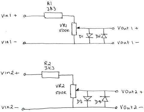
- pcscopecircuit.jpg (22.84 KiB) Viewed 1773 times
DavidPilling has spotted an issue with the data array order, full details in the link below.
https://github.com/pingumacpenguin/STM3 … -180469664
It seems I have assumed the order of the samples in the array to be ADC1, ADC2 but in reality the data appears in the array as ADC2,ADC1 and this will make the plots somewhat jaggy. I haven’t had time to verify this, as I’m caught up with other things these days, can anybody verify that David is correct. Better still can they suggest a fix. Can we change the ordering of the data as it is placed in the array, or do we simply need to honour that order while spitting out the results, to the display and/or the serial port?
I’m able to compile blinky example and other examples but I’m having a problem with O-Scope code.
I’ve already downloaded Time library and SerialCommands also.
But I’m getting these errors:
STM32-O-Scope.ino: In function ‘void setup()’:
STM32-O-Scope.ino:261:12: error: ‘setADCs’ was not declared in this scope
STM32-O-Scope.ino:266:34: error: ‘setCurrentTime’ was not declared in this scope
STM32-O-Scope.ino:267:34: error: ‘serialCurrentTime’ was not declared in this scope
I know that I can manually add the prototypes on the beggining of the code for each one but it’s a pain and if it works for other there might be something wrong in my setup…
Help? ![]()
Edit: I’m using 1.6.3 because 1.6.5 wasn’t working but I’ve tested now on 1.6.5 and it has the same errors.
#define TOUCH_SCREEN_AVAILABLE stuff doesn’t work as expected. Leave the TOUCH_SCREEN_AVAILABLE defined, and it should work.
#define TOUCH_SCREEN_AVAILABLE stuff doesn’t work as expected. Leave the TOUCH_SCREEN_AVAILABLE defined, and it should work.
<…>
Then I got the “Time” library issue, renamed to “Time1.h .cpp”.
<…>
Yes, this issue is simply an Arduino IDE issue in the way that libraries are searched … one can only have a single Time.h in the /Arduino/libraries directory. It sucks, really, but is just one of those abstract things that Arduino does.
I strongly recommend putting such code directly into the directory with the INO file(s) and encapsulate it. Hard disks are so large these days that the duplicated space is insignificant and the way the ArduinoIDE is evolving, having the Board Manager updating libraries has caused me a great deal of annoyance. Anyway, there are some environments such as Cypress PSoC development where libraries are always copied into the working folder – so the paradigm is not weird.
Ray
<…>
To solve many of these issues we could create a zip/rar file with all the necessary libraries “in a working state”
That approach makes it more dificult to share libraries and their changes but makes compilation a lot easier.
<…>
I worked some optimizations in the lcd library. It is still not the best it can, but much faster than before specially when it comes to drawing the captured data.
Download the zip attached and use that. It requires the latest SPI library from Roger’s repo.
Adafruit_ILI9341_STM.zip
Job well done… this should be a required build for any serious tinkerer who does not have access to a scope. This would be a great PSoC 4200 project due to the “free” analog subsystem and analog mux + OpAmp. FYI, only $4 http://www.cypress.com/?rID=92146
( do not even consider 4100 )
Ray
Latter I’ll test it on the board
Latter I’ll test it on the board
Take care with the backlight, the pins on the STM32F103 may not be able to source the current needed to run the display at full brightness, you may (depending on your LCD board) need to add a transistor to drive the backlight.
No, the ADC on most boards is tied to the supply voltage, so in most cases you input signal *must* be between 0v and VCC (3.3V) otherwise you will damage the ADC.
Dual channel should be relatively easy, but you will not get the full bandwith.
As to the stability of AnalogWrite, I am not aware of any instability, I suppose the best way to check for this would be to compare with a real oscilloscope.
Based on the available analog bandwidth per Alvin’s Blog post I wonder if we can over clock the ADC (at the expense of resolution presumably), and get reliable results beyond the 1MHz stated STM Spec. It looks like an interesting experiment to try. Even 8 bit resolution at say 10MHz would be useful. The GD32F103 red pill boards might also be worth a bit of over clocking experimentation, their silicon should in theory be more amenable to being driven at higher frequencies.
The GD32 boards seem to work fine at 120Mhz, but Ive not looked at whether the ADC works at that frequency.
But it is specced to 108Mhz ( but as you know, USB only works at 48,72,96 and 120Mhz because of limitations in the USB PLL clock divider)
The GD32 boards seem to work fine at 120Mhz, but Ive not looked at whether the ADC works at that frequency.
But it is specced to 108Mhz ( but as you know, USB only works at 48,72,96 and 120Mhz because of limitations in the USB PLL clock divider)
I think someone may have already looked into clock switching, but I though it breaks the USB connection
You could of course force USB re-enumeration, but that would be a pain every time you wanted to transfer data
Unfortunately the STM32 only has 2 clock divider settings for the USB PLL, but the GD32 has 4 (2 bits) (this has been possible because STM have a reserved bit in the register next to the bit for the PLL divider, so GD were able to add 2 more PLL divider settings and yet keep backwards compatibility
I think someone may have already looked into clock switching, but I though it breaks the USB connection
I’m afraid I’ve not looked at the ADC clock at all.
Looking in the manual RM0008, there is a PLL divider for the ADC clock, but I don’t know where its setup in the core.
I took a quick look in the libmaple folder at adc.c, but I can only see the setup for the number of clock cycles per sample, rather than the master PLL divider for the ADC.
I suspect the ADC clock stuff is probably setup somewhere in the RCC code, but I’m not sure where.
If someone had time to play with it, I suppose you may be able to get a bit more performance at the expense of resolution, but I wonder how useful it would actually be, or whether you’d just end up with erroneous results.
As to the stability of AnalogWrite, I am not aware of any instability, I suppose the best way to check for this would be to compare with a real oscilloscope.
With an overclocked ADC we must keep the 1.5clk on the sample time to allow a proper sampling of the signal.
But I dont suppose there is much that the cpu could do while waiting for the spi transfer to finish?
With an overclocked ADC we must keep the 1.5clk on the sample time to allow a proper sampling of the signal.
Amazon here.
This kit uses ARM Cortex-M3 processor (STM32F103C8), and includes a 2.4-inch color TFT
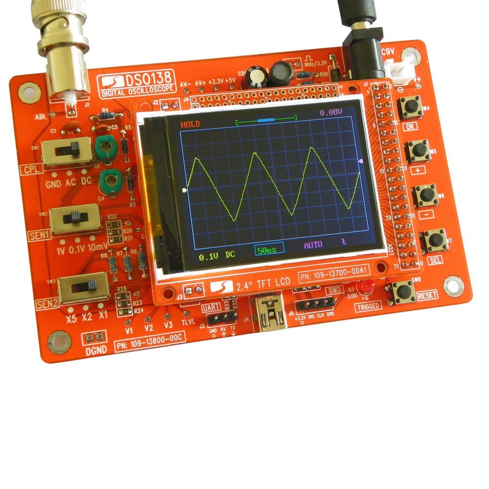
- Pig-O-Scope.jpg (153.69 KiB) Viewed 1724 times
But I dont suppose there is much that the cpu could do while waiting for the spi transfer to finish?
<…>
Well, it certainly does not come with a case for the < $30 they are asking … so, it certainly is open enclosure
Ray
DSO138 kits from Sainsmart is counterfeit product. Please see http://www.jyetech.com/Products/LcdScope/e138.php. If you have any other questions please feel free to contact us.
Best regards,
JYE Tech Sales
(Considering the cost of the components is probably less than $10.)
Maybe I’ll make a small video of the improvements. I think it’s a bit faster overall.
The Adafruit modified ILI9341 library is really fast! 34ms for a fillscreen is really good = 36Mb SPI speed. I thought SPI could only get to 18Mb using “normal” settings. Maybe somewhere there’s a DIV1 setting for the SPI module clock…?
High speeds are helped by use of DMA
High speeds are helped by use of DMA
I just read the spec..
It looks like we overclock the SPI, to twice its maximum speed.
No one has had any problems with this ![]()
<…>
It looks like we overclock the SPI, to twice its maximum speed. No one has had any problems with this
I dont think there is any need to change the core to reduce the speed even if we are overclocking.
But perhaps I should add a readme in the SPI library just so everyone is aware that we deliberatly overclock
<…>
But perhaps I should add a readme in the SPI library just so everyone is aware that we deliberatly overclock
<…>
But perhaps I should add a readme in the SPI library just so everyone is aware that we deliberatly overclock
If you look in boards_setup.cpp
e.g.
https://github.com/rogerclarkmelbourne/ … _setup.cpp
and change
#define BOARD_RCC_PLLMUL RCC_PLLMUL_9
to some other number
typedef enum rcc_pll_multiplier {

RCC_PLLMUL_2 = (0x0 << 18),

RCC_PLLMUL_3 = (0x1 << 18),

RCC_PLLMUL_4 = (0x2 << 18),

RCC_PLLMUL_5 = (0x3 << 18),

RCC_PLLMUL_6 = (0x4 << 18),

RCC_PLLMUL_7 = (0x5 << 18),

RCC_PLLMUL_8 = (0x6 << 18),

RCC_PLLMUL_9 = (0x7 << 18),

RCC_PLLMUL_10 = (0x8 << 18),

RCC_PLLMUL_11 = (0x9 << 18),

RCC_PLLMUL_12 = (0xA << 18),

RCC_PLLMUL_13 = (0xB << 18),

RCC_PLLMUL_14 = (0xC << 18),

RCC_PLLMUL_15 = (0xD << 18),

RCC_PLLMUL_16 = (0xE << 18),

} rcc_pll_multiplier;
Now I need to make some tests ![]()
Mine also has an 8Mhz crystal. So no issues here.
As for the USB, I know it won’t work but if I add some buttons to change the setting there’s no need for the USB serial command interface ![]()
The F4 series have more options for the USB divider so they are more “overclock friendly” ![]() I’ve seen STM32F429 (@180Mhz default) overclocked to 250Mhz without problems.
I’ve seen STM32F429 (@180Mhz default) overclocked to 250Mhz without problems.
I’m starting to design a board to get a F429 or a F746 working with some external RAM, an LCD and an external ADC. But time doesn’t stretch… ![]()
SPI speed is insane!!! I have videos to prove it lol From my calculations it’s probably 64Mhz!
Refresh rate is faster and it’s more responsive. It almost looks like a +$10 scope ![]()
![]()
![]()
ADC speed is maintained so still ~1.7MSPS.
Also ran the graphics test demo, it flies through the steps ![]() COOL
COOL ![]()
Tomorrow I’ll post the videos (still have to upload to youtube).
Normal speed :
https://www.youtube.com/watch?v=RQmDzVx8ovQ
Hyper speed: ![]()
https://www.youtube.com/watch?v=VOxv87-hZt8
On the video it’s not really that noticeable but there are more triggers/second as (should be) seen in the led and the waveform is more “present” on screen, the flicker (caused by the delete than redraw of the waveform) is less noticeable.
These also show the new trigger machine, trigger level working ![]()
If I had any spare time at the moment I would love to see if we can periodically over clock till triggered then drop back to standard clock to spit results to USB. I had a crack at this previously with the low power modes, but I failed to engineer a mechanism to keep USB alive with the lower clock speeds. It might be possible to massage USB in to stability with a high clock speed by some clever trickery though.
An alternative would be to add a $2 USB to serial converter on serial1 or whatever, and abandon the on board USB. The ability to send the captured data to a host using some sort of serial transfer seems to me like a “must have” feature.
Also I’ve found a simple solution for the analog bit: MCP6S92 (Single-Ended, Rail-to-Rail I/O, Low-Gain PGA)
More exactly 4 of them, 2 for each channel and also the ability to redirect either channel for ADC1 to get the ~2MSPS ![]()
This way we can get multiple gain configuration with few HW parts!
Gain ranges from 1 to 32 V/V (steps: +1, +2, +4, +5, +8, +10, +16 or +32 V/V) so we can get from 1 to 1024 total combined gain ![]()
Adding a input attenuator of 1:10 and 1MOhm we can get a functional O-scope!
I read that you can easily change voice pitches without FFT by simply recording sound in a circular buffer, and going across that buffer at a different speed for playback (with optionally some algorithm for smoothing out the wave a bit when the sampling catches you up, or vice versa).
So i took the code from this project, and set up a simple circular DMA to a buffer of 2k 16 bit samples, and slowed it down as much as possible (clock divider 8 for the ADC, 239.5 cycles sampling time), which would bring down the sampling rate to about 35khz, which is perfect for sound XD.
And then attached a DAC to my maple mini, read the buffer at various sampling rates, and it just perfectly changes the pitch of a voice, it’s incredibly simple ![]()
Had it all working in less than 2 hours of work ^^.
If you want free private git repo’s with imited private sharing, take a look at bitbucket.org
I created this one. It just uses the name anonymous if you aren’t logged into github.com
I’ve read the first 10 or so pages and am hooked! I HAVE TO make this.
Can anyone provide the final (so far) version of this project?
I’ve read the first 10 or so pages and am hooked! I HAVE TO make this.
Can anyone provide the final (so far) version of this project?
If anyone has any issues running Andy’s code, can you post it here.
Because there was a PR which made some changes to the ADC and DMA callbacks etc about a week ago, which could possibly effect things (if there was a bug)
The Arduino STM32 board manager package can be added to the IDE by following the instructions found here…
http://www.stm32duino.com/viewtopic.php?t=844
The RTC library is only part of the story, you also need the “Time” library
// Time library - https://github.com/PaulStoffregen/Time

#include "Time.h" //If you have issues with the default Time library change the name of this library to Time1 for example.
I tried seeing the random outputs in the serial monitor, but there seems to be no output. As i understand it, i’m supposed to send it a ‘s’ for it to start, but when i type in s and send it…there’s no change.
What am I doing wrong?
Also, I’m using Arduino IDE 1.6.9
  sCmd.addCommand("s",   toggleSerial);                    // Turns serial sample output on/off

sCmd.addCommand("h",   toggleHold);                      // Turns triggering on/off

sCmd.addCommand("t",   decreaseTimebase);                // decrease Timebase by 10x

sCmd.addCommand("T",   increaseTimebase);                // increase Timebase by 10x

sCmd.addCommand("z",   decreaseZoomFactor);              // decrease Zoom

sCmd.addCommand("Z",   increaseZoomFactor);              // increase Zoom

sCmd.addCommand("r",   scrollRight);                     // start onscreen trace further right

sCmd.addCommand("l",   scrollLeft);                      // start onscreen trae further left

sCmd.addCommand("e",   incEdgeType);                     // increment the trigger edge type 0 1 2 0 1 2 etc

sCmd.addCommand("y",   decreaseYposition);               // move trace Down

sCmd.addCommand("Y",   increaseYposition);               // move trace Up

sCmd.addCommand("g",   decreaseTriggerPosition);         // move trigger position Down

sCmd.addCommand("G",   increaseTriggerPosition);         // move trigger position Up

sCmd.addCommand("P",   toggleTestPulseOn);               // Toggle the test pulse pin from high impedence input to square wave output.

sCmd.addCommand("p", toggleTestPulseOff); // Toggle the Test pin from square wave test to high impedence input.
However there still wasn’t any data on the serial monitor. Which baud rate should I be using?
However there still wasn’t any data on the serial monitor. Which baud rate should I be using?
there are various advantages though, one of which is that the host computer has possibly much more resources e.g. storage and ram (possibly in gigabytes vs 20k on stm32f103cb) & much faster cpu (say multi-core i3, i5, i7 etc).
there is also a possibility to connect multiple maple-mini making it ‘parallel’ acquisition. a thing though is how to keep the start ilnes in sync across multiple maple-mini if doing ‘parallel’ scopes or for that matter to present it in a way such that it seemed ‘in-sync’ (that would turn the batteries of maple minis into a ‘multi-channel’ digital signal analyzer)
the other downside would be that an app possibly needs to be written to interface with the maple-mini to be a complete scope.
but i think what has become rather apparent so far is stm32 f1 makes ‘good scopes’. its precision is good 12 bits e.g. displays all the harmonics / tiny signals / noise riding on the main signals (e.g. square wave) and pretty much fast 1-2 msamples per sec comparable to some ‘real’ scopes. stm32 f4 with 3 adcs each 2+ m samples/s would likely be even more impressive in this aspects.
maple minis is the ‘new’ $5 ‘professional’ 1mhz scopes ![]()
https://www.fussylogic.co.uk/blog/?p=1226
& there u go, someone has been there done that as well: maple-mini scope ![]()
http://tomeko.net/miniscope_v2c/
open source has gone state-of-the-art these days
http://sigrok.org/wiki/Main_Page
http://sigrok.org/wiki/BeagleLogic
https://github.com/abhishek-kakkar/BeagleLogic/wiki
http://beta.beaglelogic.net/
BeagleLogic turns your BeagleBone Black/Green into a 100Msps Logic Analyzer with up to 14 channels. All you need is a BeagleBone, an SD card and the BeagleLogic cape to get up and running.
I have been trying to get the ADC on the stm32f103c8t6 minimum development board to sample at 1Msps using the Arduino IDE. I have tried out most of the codes on stm32duino and none of them seem to upload well. I have written a simple datalogger sketch that is able to log 10K samples/sec into an SD card . The pig o scope sketch says that it is possible to get nearly 1Msps . But i am not able to decipher the sketch. Could you help me out in pointing out methods by which i can get a higher sampling rate with logging it into an SD card or by printing it out on the serial monitor?
This is the code i’m currently running :
#include <SPI.h>

#include <SD.h>

#include <libmaple/adc.h>
const int chipSelect = PB12;
int x = 0;
unsigned long t = 0;
File dataFile;
void setup()
{
Serial.begin(250000);
delay(1000);
while (!Serial) {}
Serial.print("Initializing SD card...");
if (!SD.begin(chipSelect)) {
Serial.println("Card failed, or not present");
return;
}
Serial.println("card initialized.");
adc_set_sample_rate(ADC1, ADC_SMPR_1_5);
dataFile = SD.open("1.txt", FILE_WRITE);
t = millis();
}
void loop() {
if (!dataFile)
return;
if(Serial)
if(Serial.read()=='0') //Enter 0 to stop logging and close file
{
dataFile.close();
}
//Serial.println(analogRead(PA0));
dataFile.println(adc_read(ADC1,0));
x++;
if (millis()-t>=1000)
{
Serial.println("X=");Serial.print(x);
x = 0;
t=millis();
//dataFile.close();
}
}
...

adc_calibrate(ADC1);

adc_calibrate(ADC2);

setADCs (); //Setup ADC peripherals for interleaved continuous mode.

...
void setADCs ()
{
// const adc_dev *dev = PIN_MAP[analogInPin].adc_device;
int pinMapADCin = PIN_MAP[analogInPin].adc_channel;
adc_set_sample_rate(ADC1, ADC_SMPR_1_5); //=0,58uS/sample. ADC_SMPR_13_5 = 1.08uS - use this one if Rin>10Kohm,
adc_set_sample_rate(ADC2, ADC_SMPR_1_5); // if not may get some sporadic noise. see datasheet.
// adc_reg_map *regs = dev->regs;
adc_set_reg_seqlen(ADC1, 1);
ADC1->regs->SQR3 = pinMapADCin;
ADC1->regs->CR2 |= ADC_CR2_CONT; // | ADC_CR2_DMA; // Set continuous mode and DMA
ADC1->regs->CR1 |= ADC_CR1_FASTINT; // Interleaved mode
ADC1->regs->CR2 |= ADC_CR2_SWSTART;
ADC2->regs->CR2 |= ADC_CR2_CONT; // ADC 2 continuos
ADC2->regs->SQR3 = pinMapADCin;
}
// Grab the samples from the ADC
// Theoretically the ADC can not go any faster than this.
//
// According to specs, when using 72Mhz on the MCU main clock,the fastest ADC capture time is 1.17 uS. As we use 2 ADCs we get double the captures, so .58 uS, which is the times we get with ADC_SMPR_1_5.
// I think we have reached the speed limit of the chip, now all we can do is improve accuracy.
// See; http://stm32duino.com/viewtopic.php?f=19&t=107&p=1202#p1194
void takeSamples ()
{
// This loop uses dual interleaved mode to get the best performance out of the ADCs
//
dma_init(DMA1);
dma_attach_interrupt(DMA1, DMA_CH1, DMA1_CH1_Event);
adc_dma_enable(ADC1);
dma_setup_transfer(DMA1, DMA_CH1, &ADC1->regs->DR, DMA_SIZE_32BITS,
dataPoints32, DMA_SIZE_32BITS, (DMA_MINC_MODE | DMA_TRNS_CMPLT));// Receive buffer DMA
dma_set_num_transfers(DMA1, DMA_CH1, maxSamples / 2);
dma1_ch1_Active = 1;
// regs->CR2 |= ADC_CR2_SWSTART; //moved to setADC
dma_enable(DMA1, DMA_CH1); // Enable the channel and start the transfer.
//adc_calibrate(ADC1);
//adc_calibrate(ADC2);
samplingTime = micros();
while (dma1_ch1_Active);
samplingTime = (micros() - samplingTime);
dma_disable(DMA1, DMA_CH1); //End of trasfer, disable DMA and Continuous mode.
// regs->CR2 &= ~ADC_CR2_CONT;
/**
* @brief Enable DMA requests
* @param dev ADC device on which to enable DMA requests
*/
void adc_dma_enable(const adc_dev * dev) {
bb_peri_set_bit(&dev->regs->CR2, ADC_CR2_DMA_BIT, 1);
}
/**
* @brief Disable DMA requests
* @param dev ADC device on which to disable DMA requests
*/
void adc_dma_disable(const adc_dev * dev) {
bb_peri_set_bit(&dev->regs->CR2, ADC_CR2_DMA_BIT, 0);
}
static void DMA1_CH1_Event() {
dma1_ch1_Active = 0;
}
http://bildites.lv/a/684af4cb#v6edchda
By the way, I had to fix “UTouch” library usage, because it is now called “URTouch”, and also had to rename “Time” library, as it was proposed in sketch comments. After that, all went well. Did not try serial output yet. Clock shows year 1970. I was two back then
Thank You, and I will follow if any advances in this particular project (or a new ones too maybe)!
EDIT: i am not sure how to get serial interaction working. Should I add typical serial begin to sketch, and set baud rate?
...

adc_calibrate(ADC1);

adc_calibrate(ADC2);

setADCs (); //Setup ADC peripherals for interleaved continuous mode.

...
void setADCs ()
{
// const adc_dev *dev = PIN_MAP[analogInPin].adc_device;
int pinMapADCin = PIN_MAP[analogInPin].adc_channel;
adc_set_sample_rate(ADC1, ADC_SMPR_1_5); //=0,58uS/sample. ADC_SMPR_13_5 = 1.08uS - use this one if Rin>10Kohm,
adc_set_sample_rate(ADC2, ADC_SMPR_1_5); // if not may get some sporadic noise. see datasheet.
// adc_reg_map *regs = dev->regs;
adc_set_reg_seqlen(ADC1, 1);
ADC1->regs->SQR3 = pinMapADCin;
ADC1->regs->CR2 |= ADC_CR2_CONT; // | ADC_CR2_DMA; // Set continuous mode and DMA
ADC1->regs->CR1 |= ADC_CR1_FASTINT; // Interleaved mode
ADC1->regs->CR2 |= ADC_CR2_SWSTART;
ADC2->regs->CR2 |= ADC_CR2_CONT; // ADC 2 continuos
ADC2->regs->SQR3 = pinMapADCin;
}
// Grab the samples from the ADC
// Theoretically the ADC can not go any faster than this.
//
// According to specs, when using 72Mhz on the MCU main clock,the fastest ADC capture time is 1.17 uS. As we use 2 ADCs we get double the captures, so .58 uS, which is the times we get with ADC_SMPR_1_5.
// I think we have reached the speed limit of the chip, now all we can do is improve accuracy.
// See; http://stm32duino.com/viewtopic.php?f=19&t=107&p=1202#p1194
void takeSamples ()
{
// This loop uses dual interleaved mode to get the best performance out of the ADCs
//
dma_init(DMA1);
dma_attach_interrupt(DMA1, DMA_CH1, DMA1_CH1_Event);
adc_dma_enable(ADC1);
dma_setup_transfer(DMA1, DMA_CH1, &ADC1->regs->DR, DMA_SIZE_32BITS,
dataPoints32, DMA_SIZE_32BITS, (DMA_MINC_MODE | DMA_TRNS_CMPLT));// Receive buffer DMA
dma_set_num_transfers(DMA1, DMA_CH1, maxSamples / 2);
dma1_ch1_Active = 1;
// regs->CR2 |= ADC_CR2_SWSTART; //moved to setADC
dma_enable(DMA1, DMA_CH1); // Enable the channel and start the transfer.
//adc_calibrate(ADC1);
//adc_calibrate(ADC2);
samplingTime = micros();
while (dma1_ch1_Active);
samplingTime = (micros() - samplingTime);
dma_disable(DMA1, DMA_CH1); //End of trasfer, disable DMA and Continuous mode.
// regs->CR2 &= ~ADC_CR2_CONT;
/**
* @brief Enable DMA requests
* @param dev ADC device on which to enable DMA requests
*/
void adc_dma_enable(const adc_dev * dev) {
bb_peri_set_bit(&dev->regs->CR2, ADC_CR2_DMA_BIT, 1);
}
/**
* @brief Disable DMA requests
* @param dev ADC device on which to disable DMA requests
*/
void adc_dma_disable(const adc_dev * dev) {
bb_peri_set_bit(&dev->regs->CR2, ADC_CR2_DMA_BIT, 0);
}
static void DMA1_CH1_Event() {
dma1_ch1_Active = 0;
}
This is the writing code i am using and it takes more than a minute to log the samples.
Also is there any way i can store the values on the flash memory provided on the board ?
How much data do you need to store?
Writing to flash memory will always take some time, either on SD-card or in the internal microcontroller flash… Also you only have 128KB max. on the internal flash (and some of it will be used by the code).
Depending on the amount of data and rate you can try to use a temporary SPI RAM as a buffer…
I’ll need to store atleast 6 seconds of data, that is about 6Msps.
So if the OP is using the full range of the ADC then 2 bytes per sample would be needed.
Hence twice the data rate (12 M)
I was “trimming” it to make it simpler ![]()
If he needs more than 8 bits yes, it will double things up…
And I don’t mind having a trade-off between the number of samples I get per second as long as I get more than 100Ksps.
Try googling “site:stm32duino.com SD DMA”
P.S.: is there planned advances, changes for this Scope? Or, it was just a quick exercise that is not planned to become “bigger”? I hope it grows…
P.S.: is there planned advances, changes for this Scope? Or, it was just a quick exercise that is not planned to become “bigger”? I hope it grows…
Also, in Your tutorial is this:
https://github.com/pingumacpenguin/STM3 … l-Commands
“You must have compiled the sketch with the -DSERIAL_USB flag, so for example if you are using a genreic STM32F103C you need something like this in your boards.txt file.
genericSTM32F103C.menu.upload_method.STLinkMethod.build.upload_flags=-DCONFIG_MAPLE_MINI_NO_DISABLE_DEBUG=1 -DSERIAL_USB
(end of quote) “.
I checked, that under C:\Program Files (x86)\Arduino\hardware\Arduino_STM32\STM32F1\ in file boards.txt I have this:
genericSTM32F103C.menu.upload_method.STLinkMethod.build.upload_flags=-DCONFIG_MAPLE_MINI_NO_DISABLE_DEBUG=1 -DSERIAL_USB -DGENERIC_BOOTLOADER
so, there is one flag more, about bootloader. Should I edit now?
Or, perhaps, I am probably using genuinely outdated .INO file to start with? ![]()
I would appreciate some lessons to me, duino-STM novice ![]() Thanks!
Thanks!
If so you may have to change the baudrate on the dropdown box each time you reprogram the STM in order to receive data.
Doesn’t matter which baudrate you choose.
This happens to me all the time.
the serial functions starts only one time, I have included in the source one
statement: Serial.begin(115200); with different baudrates(9600), but no real success.
But the Touch function is ok, but the coordinates go from left to right for y and bottom for x.
The display is an 2.8″ with touch for about 11 $.
mausi_mick
I thought the in the photo you had also programmed it to play Galaxian ( https://en.wikipedia.org/wiki/Galaxian )
Perhaps the problem with the Display is, that both needs SPI-Pins (SCK, Mosi; Miso, Cs …), the UTOUCH / URTOUCH – lib is presumable Software-SPI.
Therefore I switched the Touch – before and after use – on / off:
digitalWrite(PB13,LOW); // enable Touch device ######################################
…
while ((myTouch.dataAvailable() == false) && thisCount < calibrationTries) {
…
digitalWrite(PB13,HIGH); // disable Touch device #############################################
Because of the problems with the serial-cmds I have tested
switches (on Pin PB7 … PB3 (15…20 maple mini)) with Interrupts with success:
void isr_15() { // sign for timeBase,xZoomfactor,Scroll, offset etc.
if (vorz == 0) vorz = 1;
else vorz = 0;
}
void isr_16() { // increase, decrease timeBase
if (vorz == 1) if (timeBase < 10000 ) timeBase = timeBase + 100;
if (vorz == 0) if (timeBase > 100 ) timeBase = timeBase – 100;
}
void isr_17() { // increase, decrease ZoomFactor
if (vorz == 1) if ( xZoomFactor < 21) xZoomFactor += 1;
if (vorz == 0) if ( xZoomFactor > 1) xZoomFactor -= 1;
}
void isr_18() { // ScrollRightLeft
if (vorz == 1) if (startSample < (endSample – 120)) startSample += 100; // ScrollRight
if (vorz == 0) if (startSample > (120)) startSample -= 100; // ScrollLeft
}
void isr_19() { // increase, decrease Y-Position
if (vorz == 1) if (yPosition < myHeight ) yPosition ++;
if (vorz == 0) if (yPosition > -myHeight ) yPosition –;
}
void isr_20() { // increase, decrease TriggerPosition
if (vorz == 1) if (triggerValue < ANALOG_MAX_VALUE ) triggerValue += TRIGGER_POSITION_STEP; //trigger position step
if (vorz == 0) if (triggerValue > TRIGGER_POSITION_STEP ) triggerValue -= TRIGGER_POSITION_STEP; //trigger position step
}
Now I will test the same with two quadraturencoders, the first one for the function, the second for the value.
mausi_mick
Because of the problems with the serial-cmds I have tested
switches (on Pin PB7 … PB3 (15…20 maple mini)) with Interrupts with success
Now I will test the same with two quadraturencoders, the first one for the function, the second for the value…
mausi_mick
I didn’t know that pin ISR was this simple ![]() don’t even need to clear Int. flags and stuff?… nice
don’t even need to clear Int. flags and stuff?… nice ![]()
Yep, this way it’s really easy to add an encoder to this! Even 2!!! ![]()
Therefore I had to deactivate the test pulse:
// The test pulse is a square wave of approx 3.3V (i.e. the STM32 supply voltage) at approx 1 kHz
// “The Arduino has a fixed PWM frequency of 490Hz” – and it appears that this is also true of the STM32F103 using the current STM32F03 libraries as per
// STM32, Maple and Maple mini port to IDE 1.5.x – http://forum.arduino.cc/index.php?topic=265904.2520
// therefore if we want a precise test frequency we can’t just use the default uncooked 50% duty cycle PWM output.
//timer_set_period(Timer3, 1000); //<<<<<<<<<<<<<<<<<<<<<<<<<<<
// toggleTestPulseOn();
But with the switches I had also problems: PB3 …PB7 was functioned, but switch on PA15 not.
Perhaps with the switches it’s better to take I2C.
mausi_mick
a picture from the light modified screen:
On the left thre is fot test the actual positions of encoder1 and encoder2 (in red).
In the bottom line you can see 2 Parameters : the actual used encoder – Values for encoder 1 / 2.
On the right you can see two resistors: 13 Ohm from Vcc (3.3V) to LED-Pin and 470 Ohm between Vcc and Reset-Pin.
On Youtube is a video with changing timeBase over quadrature-encoders:
with the two rotary encoders I can change the parameters .
Encoder0 is for the functions (e.g. timeBase, offset, yPos…), Encoder1 to chnage the function-parameters.
I have modified the SW to hold the Position of Encoder1, if I go with Encoder0 to another function and back.(e.g. if timeBase is in Position 2 (200µs) and I modify e.g. yPosition and go than back with the encoder0+8 to timeBase, that there is the old Position (200µs)).
The active Touch-Field is smaller than the TFT-field . On the picture I marked the region with pink circles. The Touch Centre is approximately 3mm left from the graphic centre.

- P1020567-001.JPG (164.84 KiB) Viewed 1279 times
multi_encoder_acc.zip
[url]http://www.stm32duino.com/viewtopic.php?t=15]But I have make some changes for setPosition and eliminate the acc-function (1 or 5 steps):
void readEncoders() { // ********encoder function ##################
for (byte counter = 0; counter < MAXENCODERS; counter++)
{
if ( (gpio_read_bit(PIN_MAP[encoderpinA[counter]].gpio_device, PIN_MAP[encoderpinA[counter]].gpio_bit) ? HIGH : LOW) != A_set[counter] )
{
A_set[counter] = !A_set[counter];
if ( A_set[counter] && !B_set[counter] ) encoderpos[counter] += 1;
// { if (millis() – encodertimer > 3) encoderpos[counter] += 1;
// else encoderpos[counter] += 5;
// }
encodertimer = millis();
}
if ( (gpio_read_bit(PIN_MAP[encoderpinB[counter]].gpio_device, PIN_MAP[encoderpinB[counter]].gpio_bit) ? HIGH : LOW) != B_set[counter] )
{
B_set[counter] = !B_set[counter];
if ( B_set[counter] && !A_set[counter] ) encoderpos[counter] -= 1;
// { if (millis() – encodertimer > 3) encoderpos[counter] -= 1;
// else encoderpos[counter] -= 5;
// }
encodertimer = millis();
}
}
}
and for set position:
void setEncoderPos(byte enc_nr, int16_t pos_nr)
{
encoderpos[enc_nr] = pos_nr;
}
 [ /code] tags, it makes it much easier for others to cut and paste.
[code]
void readEncoders() { // ********encoder function ##################

for (byte counter = 0; counter < MAXENCODERS; counter++)

{

if ( (gpio_read_bit(PIN_MAP[encoderpinA[counter]].gpio_device, PIN_MAP[encoderpinA[counter]].gpio_bit) ? HIGH : LOW) != A_set[counter] )

{

A_set[counter] = !A_set[counter];

if ( A_set[counter] && !B_set[counter] ) encoderpos[counter] += 1;

// { if (millis() - encodertimer > 3) encoderpos[counter] += 1;

// else encoderpos[counter] += 5;

// }
encodertimer = millis();
}

if ( (gpio_read_bit(PIN_MAP[encoderpinB[counter]].gpio_device, PIN_MAP[encoderpinB[counter]].gpio_bit) ? HIGH : LOW) != B_set[counter] )

{

B_set[counter] = !B_set[counter];

if ( B_set[counter] && !A_set[counter] ) encoderpos[counter] -= 1;

// { if (millis() - encodertimer > 3) encoderpos[counter] -= 1;

// else encoderpos[counter] -= 5;

// }

encodertimer = millis();
}

}

}
I find code a lot easier to read if its correctly indented.
If I have to work on some code, from someone else, that is not indented, one of the first things I end up doing, is to indent the bits of code I and working on.
It helps me get an understanding of how the code functions / flows
There are a number of common mistakes in C and one is confusion about the end of an “if” block especially when braces are not used ( for a single line )
I know a lot of people think this is overkill, but I generally try to put braces even for single lines inside an if block and also indent the single line accordingly.
it’s clearer an more compact.
Today I tested a little bit the touch functionality on the display,
I defined two fields on the left side of the display . The top most field is for activate witch touch a sign-bottom (+/- , up/down),
the field below is for changing the value of the timeBase.
You can see it on Youtube:
increase timebase:
https://www.youtube.com/watch?v=5ys88sK … e=youtu.be
decrease timebase:
https://www.youtube.com/watch?v=jHkaI3SEdZE
But I think with the two encoders is better
URTouch_ButtonTest Program for using with Adafruit_ILI9341_STM – lib.
The source:
[
srp
I tested the touchscreen with the modified QuickDraw-Program in the URTouch-lib.
You can see, that the circa 10% of the visible Display at the top are not usable for touch-Function,
the same on the bottom and circa 5% on the right side.
- URTouch_QuickDraw_00.ino
- (2.62 KiB) Downloaded 179 times
I will send it in a few minutes
mausi_mick
here the modified Touch-Calibration Program from the URTouch lib
with modifications for use with Adafruits-TFT-libs (ILI9341 SPI).
- STM32_URTouch_Calibration_00.ino
- (14.18 KiB) Downloaded 222 times
my test-program contains at this time both functions:
2 rotary- encoders and Touch-function (only 2 touch-fields realized for sign and timebase).
But if I test Touch (“timebase”), I switch the encoder0 in a other position , e.g yPosition or Offset.
But I think with the encoders it is more practicable and I would prefer it.
Perhaps with some “normal” switches (over interrupts), even if it is a little bit more expensive.
But I think all is open, perhaps I try Touch with a second spi display only for the parameters.
Also it’s a bit off
But this is due to the way it’s being calculated (my fault?
Seems that the encoder is a better approach in terms of speed…
here is my latest code from yesterday.
On the screen top left are two numbers visible (for test), they changed their value, if you touch the screen. It’s for test the coordinates where you have pressed.
- STM32-O-Scope-04.ino
- (42.22 KiB) Downloaded 202 times
Also it’s a bit off
But this is due to the way it’s being calculated (my fault?
Seems that the encoder is a better approach in terms of speed…
I think the price difference between encoders and pots is not big. You can get encoders for 1 or 2 US$.
But you have more flexibility.
E.g. I need encoder 0 for the functions (timeBase, Positions, trigger …) and the second encoder 1 for the values of the function.
And I am free : I take perhaps 12 switch-positions for the timebase, 20 for yPos … and I can change it by SW.
And the reaction is – because of the interrupts – quick.
mausi_mick
With the push button you can switch between the 2 (or more) functions.
For example:
1- rotate to choose function (timescale, amplitude, trigger, etc)
2- press to select function.
3- rotate to change value.
4- press to return to main “menu”.
I think the price difference between encoders and pots is not big. You can get encoders for 1 or 2 US$.
…
mausi_mick
With the push button you can switch between the 2 (or more) functions.
For example:
1- rotate to choose function (timescale, amplitude, trigger, etc)
2- press to select function.
3- rotate to change value.
4- press to return to main “menu”.
I’m going to buy some of these that already have the PCB adapter:
https://pt.aliexpress.com/item/1PCS-FRE … yId=400103
I’m going to buy some of these that already have the PCB adapter:
https://pt.aliexpress.com/item/1PCS-FRE … yId=400103
it was a good idea from You to use only one rotary encoder (and the switch-button on it).
But a little bit work …
Now the test-program is usable.
I the last line of the screen their are now tree fields with numbers for
– the last set function (1…7)
– for the last set parameter ( different depending on function)
– for the position of the encoder (yellow textcColor)
If the switch of the encoder is in Position 1 (change function), the field is grey and the text Color Black.
If the switch is in Position 2 (change parameters) , the field is magenta and the text Color Black.
If the switch is In Position 0 , the two fields are normal in green/black an the Encoder-Position
has no influence.
it was a good idea from You to use only one rotary encoder (and the switch-button on it).
Now the test-program is usable.
…
it was a good idea from You to use only one rotary encoder (and the switch-button on it).
But a little bit work …
attachInterrupt(but15, isr_15, RISING); // sign (1=increase,0=decreas)
the video on Youtube with the scope with 1 encoder :
as You suggested, I have changed the encoder.
Is working very good. No problems with bounce.Thanks !
here the code:
as You suggested, I have changed the encoder.
Is working very good. No problems with bounce.Thanks !
Seems like it’s a good reference:
http://makeatronics.blogspot.pt/2013/02 … -with.html
I need interrupt only on pin16 / PB6.
I use the EC-11 Encoder from ALPS with only 18 switch-positions. The switching characteristic is not symmetric :
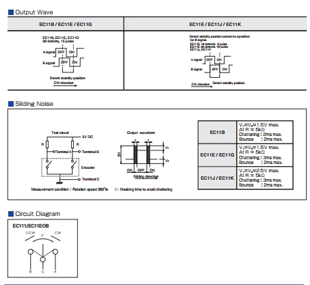
- EC-11_Switch_Characteristic.jpg (77.1 KiB) Viewed 1377 times
Ok, I see now. With the EC11-E… types you can use only one interrupt.
Maybe this was the main idea for them to create this type of switching… hummm
When compiling “06”, “07” I got warnings about “void dma_setup_transfer”, could be this related (sorry my poor knowledge)? Warnings:
E:\Elektron\OSC\STM32-O-Scope\mausi_mick\STM32-O-Scope-07\STM32-O-Scope-07.ino: In function 'void takeSamples()':
E:\Elektron\OSC\STM32-O-Scope\mausi_mick\STM32-O-Scope-07\STM32-O-Scope-07.ino:732:3: warning: 'void dma_setup_transfer(dma_dev*, dma_channel, volatile void*, dma_xfer_size, volatile void*, dma_xfer_size, uint32)' is deprecated (declared at C:\Program Files (x86)\Arduino\hardware\Arduino_STM32\STM32F1\system/libmaple/stm32f1/include/series/dma.h:563) [-Wdeprecated-declarations]
dma_setup_transfer(DMA1, DMA_CH1, &ADC1->regs->DR, DMA_SIZE_32BITS,
^
E:\Elektron\OSC\STM32-O-Scope\mausi_mick\STM32-O-Scope-07\STM32-O-Scope-07.ino:733:85: warning: 'void dma_setup_transfer(dma_dev*, dma_channel, volatile void*, dma_xfer_size, volatile void*, dma_xfer_size, uint32)' is deprecated (declared at C:\Program Files (x86)\Arduino\hardware\Arduino_STM32\STM32F1\system/libmaple/stm32f1/include/series/dma.h:563) [-Wdeprecated-declarations]
dataPoints32, DMA_SIZE_32BITS, (DMA_MINC_MODE | DMA_TRNS_CMPLT));// Receive buffer DMA
Therefore you need a flag, set in the encoder-isr and reset by the set_func/value:
volatile boolean enc_flag= false;
The Pointlessly Small Pig-O-Scope… complete with 128×128 pixels and 1.44″ of almost illegible 1kHz square wave for your amusement.

- RIMG0090_small.JPG (203.14 KiB) Viewed 1762 times
The Pointlessly Small Pig-O-Scope… complete with 1.44″ of almost illegible 1kHz square wave for your amusement.
If anybody fancies merging this cut down version back in to the main variant, send me a git pull request.
The Pointlessly Small Pig-O-Scope… complete with 1.44″ of almost illegible 1kHz square wave for your amusement.
If anybody fancies merging this cut down version back in to the main variant, send me a git pull request.
Yes, the tiny version is a lunchtime entertainment project, not intended for anything other than keeping me amused.
Why not the 0.96″ OLED?
They should work with the UTFT libs, so I ordered one. The OLED comes in several different flavours and is slightly more expensive, and obviously has not touch panel. I imagine that the majority of these cheap TFT displays with touch panels are “recovered stock”, similar to the large number of “Nokia 5110” monochrome displays. I think the Nokia ones still win out then it comes to low power consumption, but its a close run contest since for a lot of these displays, the majority of the power is used in the backlight.
I wonder if it would be worth adding supported displays to the Wiki, what does everyone think? ![]()
The second one you mentioned is an ILI9341 based display, so in theory it will work fine with the ‘scope too. If you look through the forum I think you will find pages about both of those controllers. The 3.5″ display should let you drive it with either 16 GPIO pons or 8 by the look of the connector, some research on the controller to figure how to do use 16 bit may be needed, unless anyone else here has used this display.
I have tested a little bit with the URTouch lib,
only realized for timeBase and yPosition.
But it is not so comfortable in comparison with the rotary-encoders.
Partly because of it function with polling in the loop().
Here a picture from the menu:
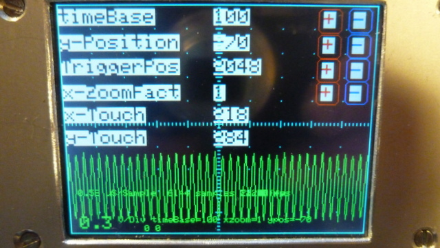
- P1020590.JPG (134.68 KiB) Viewed 1403 times
One option would be to do timer interrupt driven polling. That might be more responsive.
on the bottom right corner I have an invisible touch-field for start and stop the touch-menu.
Now are realized these functions : timeBase (step-width 100), y_position (step-width 10) and y-ZoomFactor (100…500=1-5).
If you use bigger touch-fields with more distance to the edge, you can manipulate it with your fingers.
The Pointlessly Small Pig-O-Scope… complete with 128×128 pixels and 1.44″ of almost illegible 1kHz square wave for your amusement.
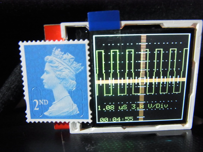
Small but (almost) perfectly formed. The photo doesn’t do it justice.. that little display should come with a pair of binoculars just to read it. ![]()
oh wow ‘smart watch’ ‘wearable’ O-scope, add accelerometer & 1 could graph that 100m sprint or walk in the park
oh wow ‘smart watch’ ‘wearable’ O-scope, add accelerometer & 1 could graph that 100m sprint or walk in the park
I have tested a little bit with the URTouch lib,
only realized for timeBase and yPosition.
But it is not so comfortable in comparison with the rotary-encoders.
Partly because of it function with polling in the loop().
Here a picture from the menu:
P1020590.JPG
baut it’s only for the front-side.
I had problems with the maple-mini on a bread-board (i think to much capacity between the pins. Therefore I have to make
my own layout (but simple, copper cut with a box cutter).
I have changed the touch menu for handle with small ? fingers:
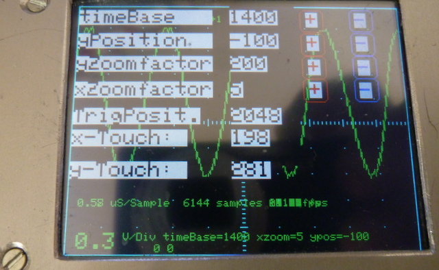
- P1020596.JPG (125.47 KiB) Viewed 1433 times
It’s a 2.8″ SPI TFT-display with ILI9341 with No. TCJTM24028-SPI.
I have other diplays With ILI9327 and ILI9841, but I have problems with the displays on STM32F103 / Maple Mini Clone
If I change the Triggerposition/Value or the x-ZoomFactor, the program crashes…
Other manpulations are stable.
I am trying to get the Pig-O-Scope running on the Blue Pill.
while the scope itself seems to work ok, I am having
trouble with serial I/O.
// Create USB serial port

USBSerial serial_debug;
void setup()
{
....
serial_debug.begin();
serial_debug.println("Hello from serial_debug");
The serial output should come out of the USB serial device.
The issue seems to be with line endings (<cr><lf>), and/or serial handshaking (DTR/DSR, X-ON/X-OFF).
You may need to experiment with the line ending settings and possibly also handshake (DTR/DSR etc) on your particular terminal emulator to get reliable output. This is not unique to the o-scope, I have had similar trouble with other code using Arduino serial output.
And … What UART port does SerialCommand sCmd;
use?
And … What UART port does SerialCommand sCmd;
use?
Re: SerialCommand:
CRLF mapping in the terminal program did the trick….
Re: SerialCommand:
CRLF mapping in the terminal program did the trick….
They should work with the UTFT libs, so I ordered one. …
They should work with the UTFT libs, so I ordered one. …
The serial output should come out of the USB serial device.
The serial output should come out of the USB serial device.
I imagine it would be awesome if we have systematized updated links to current, “latest and greatest” versions of “O-Scope” somewhere easily accessible without lot of searching. I guess it could be “sticky” first post of this thread, for example. With links to current versions of code from various users who are creating “forks”. Sometimes it is done in first post Author’s signature link.
Can we wish that, for Christmas?
Please, question to mausi_mick: I presume you are also Windows user, and, judging from your earlier posts, also struggling to have any serial interaction? Or maybe any success, that you could share? It kinda looks like serial connection is possible only for non-Windows users here. I can hope that I am wrong. And, mausi_mick, what is your current code that youi like yourslef? Is it encoder-oriented, or touch, or both maybe? Thanks in advance!
All pull requests and Wiki edits are welcome. If you figure out the cause of your Windows serial woes (short of installing a real operating system of course
Last time I tested other displays on STM32 (ILI9327, ILI9481), but with no success.
And in this thread i tested a little bit with Touch (URTouch-lib) .
On a 2.8″ ILI9341 display it’s possible to change the parameters over touch with your fingers, on smaller displays you have to take a stick or make the changes over encoder(s).
Wishes for the new year:
–
–
–
– a second channel for the O_Scope ( for testing quadrature encoders … )
– a bigger display with more pixel (like ILI9481-8bit? 480 x 320)) for display the signal with 8-bit resolution.
Here’s the diff between the hacked TFT_ILI9163C 1.4″ version (first) and the original Adafruit_ILI9341_STM git version (second) so you can see what changes were needed. I don’t intend to support different displays, but if you fancy doing the work in such a way that you can define the display type and automagically include the correct libs, then feel free to give it a go. You may need to trim out some of the bloat, and define a better set of colour names too.
1,2c1,2

< /*.

<   (c) Andrew Hull - 2015

---

>  /*.

> (c) Andrew Hull - 2015

4c4

<   STM32-O-Scope - aka "The Pig Scope" or pigScope released under the GNU GENERAL PUBLIC LICENSE Version 2, June 1991

---

> STM32-O-Scope - aka "The Pig Scope" or pigScope released under the GNU GENERAL PUBLIC LICENSE Version 2, June 1991

6c6

<   https://github.com/pingumacpenguin/STM32-O-Scope

---

> https://github.com/pingumacpenguin/STM32-O-Scope

8c8

<   Adafruit Libraries released under their specific licenses Copyright (c) 2013 Adafruit Industries.  All rights reserved.

---

> Adafruit Libraries released under their specific licenses Copyright (c) 2013 Adafruit Industries.  All rights reserved.

12,13c12,13

< //#include "Adafruit_ILI9341_STM.h"

< //#include "Adafruit_GFX_AS.h"

---

> #include "Adafruit_ILI9341_STM.h"

> #include "Adafruit_GFX_AS.h"

19c19

< #define LANDSCAPE 3

---

> #define LANDSCAPE 1

21,26d20

< // Define the orientation of the touch screen. Further

< // information can be found in the UTouch library documentation.

<

< // #define TOUCH_SCREEN_AVAILABLE

<

< #define TOUCH_ORIENTATION  LANDSCAPE

28,33d21

< #ifdef TOUCH_SCREEN_AVAILABLE

< // UTouch Library

< // http://www.rinkydinkelectronics.com/library.php?id=56

< #include <UTouch.h>

<

< #endif

48d35

< #ifdef TOUCH_SCREEN_AVAILABLE

50c37,42

< UTouch  myTouch( PB12, PB13, PB14, PB15, PA8);

---

> // Also define the orientation of the touch screen. Further

> // information can be found in the UTouch library documentation.

> //

>

> // This makes no sense.. (BUG) but if you don't actually have a touch screen, you need to declere it anyway then  #undef it below.

> #define TOUCH_SCREEN_AVAILABLE

51a44,49

> #if defined TOUCH_SCREEN_AVAILABLE

> #define TOUCH_ORIENTATION  LANDSCAPE

> // UTouch Library

> // http://www.rinkydinkelectronics.com/library.php?id=56

> #include <UTouch.h>

> UTouch  myTouch( PB12, PB13, PB14, PB15, PA8);

53a52,55

> // This makes no sense.. (BUG) but if you don't actually have a touch screen, #undef it here.

> #undef TOUCH_SCREEN_AVAILABLE

>

>

77c79

< #include "Time.h"

---

> #include "Time.h" //If you have issues with the default Time library change the name of this library to Time1 for example.

84a87

> /* For reference on STM32F103CXXX

86,88c89,98

< #define BOARD_LED      PC13

< //#define TFT_LED        PC13          // Backlight

< #define TEST_WAVE_PIN       PB0     // PWM 500 Hz

---

> variants/generic_stm32f103c/board/board.h:#define BOARD_NR_SPI              2

> variants/generic_stm32f103c/board/board.h:#define BOARD_SPI1_NSS_PIN        PA4

> variants/generic_stm32f103c/board/board.h:#define BOARD_SPI1_MOSI_PIN       PA7

> variants/generic_stm32f103c/board/board.h:#define BOARD_SPI1_MISO_PIN       PA6

> variants/generic_stm32f103c/board/board.h:#define BOARD_SPI1_SCK_PIN        PA5

>

> variants/generic_stm32f103c/board/board.h:#define BOARD_SPI2_NSS_PIN        PB12

> variants/generic_stm32f103c/board/board.h:#define BOARD_SPI2_MOSI_PIN       PB15

> variants/generic_stm32f103c/board/board.h:#define BOARD_SPI2_MISO_PIN       PB14

> variants/generic_stm32f103c/board/board.h:#define BOARD_SPI2_SCK_PIN        PB13

90,109d99

<

< /*

<    Connections to an STM32F103CXXX board as follows. (Wire colours for reference only, clearly you can use whatever colours you please).

<   NOTE: While most of the cheap "ILI9163C 128x128 TFT" boards will probably work you may also need to set the board type in TFT_ILI9163C.h

<   Also, the STM32F103XXX boards are 3v3 devices, as is the display, so you can in fact short out the link across the regulator on the display and power it directly from the 3v3 on the STM board.

<

<   Pinout  - (TFT => stm32duino)

<   LED to 3.3V   - Orange  - Could also be taken to a suitable pin + transistor to drive the backlight.

<                            NOTE: The backlight will probably draw far too much current for one GPIO pin to handle unbuffered.

<

<   SCK to PA5    - Yellow  - STM32 -> SPI1_SCK      - These two SPI pins are hardware defined pins

<   SDA to PA7    - Greeen  - STM32 -> SPI1_MOSI     -

<

<                -           The exact pin number of the next three pins are not critical, you should be able to use and GPIO, update the below #defines and it should work.

<   A0 to PB6     - Blue

<   RST to PB5    - Violet    - Can also be tied to STM32_NRST, so save a GPIO pin.

<   CS to PB7     - Grey

<

<   GND to GND    - Brown

<   VCC to 3.3V   - Red

111,114d100

< // Additional SPI1 pins.

< #define RST PB5

< #define DC PB8

< #define CS PB9

115a102,113

> // Additional  display specific signals (i.e. non SPI) for STM32F103C8T6 (Wire colour)

> #define TFT_DC      PA0      //   (Green)

> #define TFT_CS      PA1      //   (Orange)

> #define TFT_RST     PA2      //   (Yellow)

>

> // Hardware SPI1 on the STM32F103C8T6 *ALSO* needs to be connected and pins are as follows.

> //

> // SPI1_NSS  (PA4) (LQFP48 pin 14)    (n.c.)

> // SPI1_SCK  (PA5) (LQFP48 pin 15)    (Brown)

> // SPI1_MOSO (PA6) (LQFP48 pin 16)    (White)

> // SPI1_MOSI (PA7) (LQFP48 pin 17)    (Grey)

> //

117,118c115,116

< #include "TFT_ILI9163C.h"

< TFT_ILI9163C TFT = TFT_ILI9163C(CS, DC, RST);

---

> #define TFT_LED        PA3     // Backlight

> #define TEST_WAVE_PIN       PB1     //PB1 PWM 500 Hz

119a118,119

> // Create the lcd object

> Adafruit_ILI9341_STM TFT = Adafruit_ILI9341_STM(TFT_CS, TFT_DC, TFT_RST); // Using hardware SPI

123,159c123

< #define BOARD_LED PC13

<

< #ifndef  ILI9341_BLACK

< // Color definitions from ILI9341

< // FIXME: I should stick to a subset of real colours, and avoid the Adafruit ones.

< #define ILI9341_BLACK       0x0000      /*   0,   0,   0 */

< #define ILI9341_NAVY        0x000F      /*   0,   0, 128 */

< #define ILI9341_DARKGREEN   0x03E0      /*   0, 128,   0 */

< #define ILI9341_DARKCYAN    0x03EF      /*   0, 128, 128 */

< #define ILI9341_MAROON      0x7800      /* 128,   0,   0 */

< #define ILI9341_PURPLE      0x780F      /* 128,   0, 128 */

< #define ILI9341_OLIVE       0x7BE0      /* 128, 128,   0 */

< #define ILI9341_LIGHTGREY   0xC618      /* 192, 192, 192 */

< #define ILI9341_DARKGREY    0x7BEF      /* 128, 128, 128 */

< #define ILI9341_BLUE        0x001F      /*   0,   0, 255 */

< #define ILI9341_GREEN       0x07E0      /*   0, 255,   0 */

< #define ILI9341_CYAN        0x07FF      /*   0, 255, 255 */

< #define ILI9341_RED         0xF800      /* 255,   0,   0 */

< #define ILI9341_MAGENTA     0xF81F      /* 255,   0, 255 */

< #define ILI9341_YELLOW      0xFFE0      /* 255, 255,   0 */

< #define ILI9341_WHITE       0xFFFF      /* 255, 255, 255 */

< #define ILI9341_ORANGE      0xFD20      /* 255, 165,   0 */

< #define ILI9341_GREENYELLOW 0xAFE5      /* 173, 255,  47 */

< #define ILI9341_PINK        0xF81F

<

< // Colours are RGB565 - try this site for a colour picker --> http://www.barth-dev.de/online/rgb565-color-picker/

< #define TFT_GREY 0x5AEB

< #define TFT_BLACK 0x0000

< #define TFT_WHITE 0xFFFF

< #define TFT_RED 0xFB03

< #define TFT_GREEN 0x37E0

< #define TFT_BLUE 0x081F

< #define TFT_ORANGE 0xFC80

< #define TFT_MAGENTA 0xF817

< #define TFT_YELLOW 0xE7E0

<

< #endif

---

> #define BOARD_LED PC13 //PB0

168,169d131

<

<

171d132

< #define ANALOG_INPUT_1 PB1

173c134

< const int8_t analogInPin = ANALOG_INPUT_1 ;   // Analog input pin: any of LQFP44 pins (PORT_PIN), 10 (PA0), 11 (PA1), 12 (PA2), 13 (PA3), 14 (PA4), 15 (PA5), 16 (PA6), 17 (PA7), 18 (PB0), 19  (PB1)

---

> const int8_t analogInPin = PB0;   // Analog input pin: any of LQFP44 pins (PORT_PIN), 10 (PA0), 11 (PA1), 12 (PA2), 13 (PA3), 14 (PA4), 15 (PA5), 16 (PA6), 17 (PA7), 18 (PB0), 19  (PB1)

174a136

> float displayTime = 0;

183,187c145,146

< int16_t yZoomFactor = 50

<                       ;

<

< //int16_t yPosition = -150 ;

< int16_t yPosition = 20 ;

---

> int16_t yZoomFactor = 100; //Adjusted to get 3.3V wave to fit on screen

> int16_t yPosition = 0 ;

194c153

< unsigned long timeBase = 100;  // Timebase in microseconds

---

> unsigned long timeBase = 200;  //Timebase in microseconds

205d163

< int32_t triggerSensitivity = 6;

207,208c165,171

< int16_t retriggerDelay = 10;

< int8_t triggerType = 1;

---

> // Trigger is setup in one of 32 positions

> #define TRIGGER_POSITION_STEP ANALOG_MAX_VALUE/32

> // Trigger default position (half of full scale)

> int32_t triggerValue = 2048;

>

> int16_t retriggerDelay = 0;

> int8_t triggerType = 2; //0-both 1-negative 2-positive

225,226c188,189

< # define maxSamples 1024*6

< uint32_t startSample = 10;

---

> # define maxSamples 1024*6 //1024*6

> uint32_t startSample = 0; //10

229d191

<

234a197,200

> //array for computed data (speedup)

> uint16_t dataPlot[320]; //max(width,height) for this display

>

>

243,244c209

<   serial_debug.begin();

<   /*

---

>

246c211

<   #ifdef BOARD_LED

---

> #if defined BOARD_LED

247a213,219

>   digitalWrite(BOARD_LED, HIGH);

>   delay(1000);

>   digitalWrite(BOARD_LED, LOW);

>   delay(1000);

> #endif

>   pinMode(TFT_LED, OUTPUT);

>   digitalWrite(TFT_LED, HIGH);

249,255c221

<   for (  int i = 0; i < 30; i++)

<   {

<     blinkLED(100);

<   }

<   #endif

<   */

<

---

>   serial_debug.begin();

281c247,249

<   sCmd.addCommand("Y",   increaseYposition);               // move trace Down

---

>   sCmd.addCommand("Y",   increaseYposition);               // move trace Up

>   sCmd.addCommand("g",   decreaseTriggerPosition);         // move trigger position Down

>   sCmd.addCommand("G",   increaseTriggerPosition);         // move trigger position Up

302a271

>

314,317c283,285

<   TFT.fillScreen(TFT_BLACK);

<

<   //TFT.setRotation(2);

<   //TFT.setRotation(PORTRAIT);

---

>   // initialize the display

>   clearTFT();

>   TFT.setRotation(PORTRAIT);

326a295

> //  showGraticule();

328,329c297

<   showGraticule();

<   delay(3000) ;

---

>   delay(1000) ; //5000

348d315

<     showGraticule();

351,358c318

<       blinkLED(10);

<       //Blank  out previous plot

<       TFTSamples(BEAM_OFF_COLOUR);

<       showLabels();

<

<       // Show the showGraticule

<       showGraticule();

<       //notTriggered = true;

---

>       blinkLED();

361a322,324

>

>       //Blank  out previous plot

>       TFTSamplesClear(BEAM_OFF_COLOUR);

363,364c326,327

<       // Display the Labels ( uS/Div, Volts/Div etc).

<       showLabels();

---

>       // Show the showGraticule

>       showGraticule();

367a331,335

>       displayTime = (micros() - displayTime);

>

>       // Display the Labels ( uS/Div, Volts/Div etc).

>       showLabels();

>       displayTime = micros();

368a337,338

>     }else {

>           showGraticule();

395c365

<       TFT.drawFastHLine(  (myHeight / 2) - 1 , TicksX, 3, TFT_RED);

---

>       TFT.drawFastHLine(  (myHeight / 2) - 1 , TicksX, 3, GRATICULE_COLOUR);

399c369

<       TFT.drawFastHLine(  (myHeight / 2) - 5 , TicksX, 11, GRATICULE_COLOUR);

---

>       TFT.drawFastHLine(  (myHeight / 2) - 3 , TicksX, 7, GRATICULE_COLOUR);

407c377

<       TFT.drawFastVLine( TicksY,  (myWidth / 2) - 1 , 3, TFT_RED);

---

>       TFT.drawFastVLine( TicksY,  (myWidth / 2) - 1 , 3, GRATICULE_COLOUR);

411c381

<       TFT.drawFastVLine( TicksY,  (myWidth / 2) - 5 , 11, GRATICULE_COLOUR);

---

>       TFT.drawFastVLine( TicksY,  (myWidth / 2) - 3 , 7, GRATICULE_COLOUR);

420,421c390,391

<   adc_set_sample_rate(ADC1, ADC_SMPR_13_5);

<   adc_set_sample_rate(ADC2, ADC_SMPR_13_5);

---

>   adc_set_sample_rate(ADC1, ADC_SMPR_1_5); //=0,58uS/sample.  ADC_SMPR_13_5 = 1.08uS - use this one if Rin>10Kohm,

>   adc_set_sample_rate(ADC2, ADC_SMPR_1_5);    // if not may get some sporadic noise. see datasheet.

455,457c425,431

<   delayMicroseconds(20);

<   if (((analogRead(analogInPin) - triggerPoints[0] ) < triggerSensitivity) or ((triggerPoints[0] - analogRead(analogInPin) ) < triggerSensitivity)) {

<     notTriggered = false ;

---

>   while(notTriggered){

>     triggerPoints[1] = analogRead(analogInPin);

>     if ( ((triggerPoints[1] < triggerValue) && (triggerPoints[0] > triggerValue)) ||

>          ((triggerPoints[1] > triggerValue) && (triggerPoints[0] < triggerValue)) ){

>       notTriggered = false;

>     }

>     triggerPoints[0] = triggerPoints[1]; //analogRead(analogInPin);

462,466d435

<

<   triggerPoints[1] = analogRead(analogInPin);

<   if ((triggerPoints[1] - triggerPoints[0] ) > triggerSensitivity) {

<     notTriggered = false;

<   }

467a437,443

>   while(notTriggered){

>     triggerPoints[1] = analogRead(analogInPin);

>     if ((triggerPoints[1] > triggerValue) && (triggerPoints[0] < triggerValue) ){

>       notTriggered = false;

>     }

>     triggerPoints[0] = triggerPoints[1]; //analogRead(analogInPin);

>   }

471,475d446

<

<   triggerPoints[1] = analogRead(analogInPin);

<   if ((triggerPoints[0] - triggerPoints[1] ) > triggerSensitivity) {

<     notTriggered = false;

<   }

476a448,454

>   while(notTriggered){

>     triggerPoints[1] = analogRead(analogInPin);

>     if ((triggerPoints[1] < triggerValue) && (triggerPoints[0] > triggerValue) ){

>       notTriggered = false;

>     }

>     triggerPoints[0] = triggerPoints[1]; //analogRead(analogInPin);

>   }

486,488c464,466

<     serial_debug.println(triggerPoints[0]);

<     serial_debug.println(triggerPoints[1]);

<     serial_debug.println(triggerType);

---

>   serial_debug.println(triggerPoints[0]);

>   serial_debug.println(triggerPoints[1]);

>   serial_debug.println(triggerType);

497c475

< void blinkLED(uint16_t duration)

---

> void blinkLED()

501c479

<   delay(duration);

---

>   delay(10);

539a518,525

> void TFTSamplesClear (uint16_t beamColour)

> {

>   for (signalX=1 ; signalX < myWidth - 2; signalX++)

>   {

>     //use saved data to improve speed

>     TFT.drawLine (  dataPlot[signalX-1], signalX, dataPlot[signalX] , signalX + 1, beamColour) ;

>   }

> }

544,545c530,534

<   signalX = 1;

<   while (signalX < myWidth - 2)

---

>   //calculate first sample

>   signalY =  ((myHeight * dataPoints[0 * ((endSample - startSample) / (myWidth * timeBase / 100)) + 1]) / ANALOG_MAX_VALUE) * (yZoomFactor / 100) + yPosition;

>   dataPlot[0]=signalY * 99 / 100 + 1;

>

>   for (signalX=1 ; signalX < myWidth - 2; signalX++)

549,558c538,541

<     signalY =  (((myHeight * dataPoints[signalX * ((endSample - startSample) / (myWidth * timeBase / 100)) + 1]) / ANALOG_MAX_VALUE) * yZoomFactor ) / 100 + yPosition;

<     signalY1 = (((myHeight * dataPoints[(signalX + 1) * ((endSample - startSample) / (myWidth * timeBase / 100)) + 1]) / ANALOG_MAX_VALUE) * yZoomFactor ) / 100 + yPosition ;

<     TFT.drawLine (  signalY * 99 / 100 + 1, signalX, signalY1 * 99 / 100 + 1 , signalX + 1, beamColour) ;

<     signalX += 1;

<     /*

<       serial_debug.println((myHeight * dataPoints[signalX * ((endSample - startSample) / (myWidth * timeBase / 100)) + 1]) / ANALOG_MAX_VALUE);

<       serial_debug.println(dataPoints[(signalX + 1) * ((endSample - startSample) / (myWidth * timeBase / 100)) + 1]);

<       serial_debug.println(yZoomFactor/100);

<       serial_debug.println(yPosition);

<     */

---

>     signalY1 = ((myHeight * dataPoints[(signalX + 1) * ((endSample - startSample) / (myWidth * timeBase / 100)) + 1]) / ANALOG_MAX_VALUE) * (yZoomFactor / 100) + yPosition ;

>     dataPlot[signalX] = signalY1 * 99 / 100 + 1;

>     TFT.drawLine (  dataPlot[signalX-1], signalX, dataPlot[signalX] , signalX + 1, beamColour) ;

>     signalY = signalY1;

563,564c546,547

<   // Run a bunch of NOOPs to trim the inter ADC conversion gap

<   void sweepDelay(unsigned long sweepDelayFactor) {

---

> // Run a bunch of NOOPs to trim the inter ADC conversion gap

> void sweepDelay(unsigned long sweepDelayFactor) {

569c552

<   }

---

> }

575,576c558,559

<   TFT.setTextSize(0);

<   TFT.setCursor(2, 100);

---

>   TFT.setTextSize(1);

>   TFT.setCursor(10, 190);

581,583c564,572

<   TFT.setTextSize(0);

<   TFT.print(" uS ");

<   TFT.setTextSize(0);

---

>   TFT.setTextSize(1);

>   TFT.print(" uS/Sample  ");

>   TFT.print(maxSamples);

>   TFT.print(" samples ");

> //  TFT.setCursor(10, 190);

> //  TFT.print(displayTime);

>   TFT.print(float (1000000 / float(displayTime)));

>   TFT.print(" fps    ");

>   TFT.setTextSize(2);

585,586c574,575

<   TFT.print("3.0");

<   TFT.setTextSize(0);

---

>   TFT.print("0.3");

>   TFT.setTextSize(1);

588,595c577,584

<   /* Not enough room on 128*128 for all of the lables

<     TFT.setTextSize(0);

<     TFT.print(samplingTime);

<     TFT.setTextSize(0);

<     TFT.print(" us for ");

<     TFT.print(maxSamples);

<     TFT.print(" samples ");

<   */

---

>   TFT.setTextSize(1);

>

>   TFT.print("timeBase=");

>   TFT.print(timeBase);

>   TFT.print(" yzoom=");

>   TFT.print(yZoomFactor);

>   TFT.print(" ypos=");

>   TFT.print(yPosition);

603c592

<   TFT.setTextSize(0);

---

>   TFT.setTextSize(1);

608c597

<     TFT.setCursor(5, 120);

---

>     TFT.setCursor(5, 10);

623,631c612,618

<     /*  Not enough room on 128*128 display for date

<       TFT.print(" ");

<       TFT.print(day(tt));

<       TFT.print("-");

<       TFT.print(month(tt));

<       TFT.print("-");

<       TFT.print(year(tt));

<       TFT.print(" "TZ" ");

<     */

---

>     TFT.print(" ");

>     TFT.print(day(tt));

>     TFT.print("-");

>     TFT.print(month(tt));

>     TFT.print("-");

>     TFT.print(year(tt));

>     TFT.print(" "TZ" ");

655,656c642

<     //serial_debug.print("\n");

<     serial_debug.println();

---

>     serial_debug.print("\n");

695,696c681,682

<     sweepDelayFactor =  sweepDelayFactor / 2 ;

<     if (sweepDelayFactor < 1 ) {

---

>   sweepDelayFactor =  sweepDelayFactor / 2 ;

>   if (sweepDelayFactor < 1 ) {

700c686

<     }

---

>   }

801a788,806

>

> void increaseTriggerPosition() {

>

>   if (triggerValue < ANALOG_MAX_VALUE ) {

>     triggerValue += TRIGGER_POSITION_STEP;  //trigger position step

>   }

>   Serial.print("# TriggerPosition=");

>   Serial.println(triggerValue);

> }

>

> void decreaseTriggerPosition() {

>

>   if (triggerValue > 0 ) {

>     triggerValue -= TRIGGER_POSITION_STEP;  //trigger position step

>   }

>   Serial.print("# TriggerPosition=");

>   Serial.println(triggerValue);

> }

>

833,834c838,839

<   @brief Enable DMA requests

<   @param dev ADC device on which to enable DMA requests

---

> * @brief Enable DMA requests

> * @param dev ADC device on which to enable DMA requests

843,844c848,849

<   @brief Disable DMA requests

<   @param dev ADC device on which to disable DMA requests

---

> * @brief Disable DMA requests

> * @param dev ADC device on which to disable DMA requests

884d888

<   // Not enough space on  128*128 display but OK on serial

996,1003c1000,1001

<   TFT.setTextColor(TFT_RED, BEAM_OFF_COLOUR) ;

<   TFT.setTextSize(0);                           // Tiny font

<   TFT.setCursor(0, 10);

<   TFT.print("STM-O-Scope") ;

<   TFT.setCursor(0, 30);

<   TFT.print(" Andy Hull");

<   TFT.setCursor(0, 40);

<   TFT.print(" Ray Burnette.");

---

>   TFT.setTextSize(2);                           // Small 26 char / line

>   //TFT.setTextColor(CURSOR_COLOUR, BEAM_OFF_COLOUR) ;

1005,1007c1003

<   TFT.print(" Victor PV");

<   TFT.setCursor(0, 60);

<   TFT.print(" Roger Clark");

---

>   TFT.print(" STM-O-Scope by Andy Hull") ;

1009,1013c1005

<   TFT.print("stm32duino.com");

<   TFT.setCursor(0, 80);

<   TFT.print("Probe Pin [");

<   TFT.print("PB1");

<   TFT.print("]");

---

>   TFT.print("      Inspired by");

1015,1020c1007,1022

<   TFT.setTextSize(0);

<   TFT.print("GPL Ver. 2 ");

<   TFT.setTextColor(CURSOR_COLOUR, BEAM_OFF_COLOUR) ;

<   //delay(3000);

<   //TFT.setTextSize(2);

<   //TFT.setRotation(PORTRAIT);

---

>   TFT.print("      Ray Burnette.");

>   TFT.setCursor(0, 130);

>   TFT.print("      Victor PV");

>   TFT.setCursor(0, 150);

>   TFT.print("      Roger Clark");

>   TFT.setCursor(0, 170);

>   TFT.print(" and all at stm32duino.com");

>   TFT.setCursor(0, 190);

>   TFT.print(" CH1 Probe STM32F Pin [");

>   TFT.print(analogInPin);

>   TFT.print("]");

>   TFT.setCursor(0, 220);

>   TFT.setTextSize(1);

>   TFT.print("     GNU GENERAL PUBLIC LICENSE Version 2 ");

>   TFT.setTextSize(2);

>   TFT.setRotation(PORTRAIT);

1057,1077d1058

< void send_command(int command, void *message)

< {

<    asm("mov r0, %[cmd];"

<        "mov r1, %[msg];"

<        "bkpt #0xAB"

<          :

<          : [cmd] "r" (command), [msg] "r" (message)

<          : "r0", "r1", "memory");

< }

<

< void put_char(char c)

< {

<     asm (

<     "mov r0, #0x03\n"   /* SYS_WRITEC */

<     "mov r1, %[msg]\n"

<     "bkpt #0xAB\n"

<     :

<     : [msg] "r" (&c)

<     : "r0", "r1"

<     );

< }
I figure the current BOM is probably nearer $6 than $10 since the STM boards are ubercheap, so a double headed pig-o-scope could be built for a bit less than $20. The advantage of having two is that you still have the full bandwidth on the channels. If you do go down this road, you might need to invent some way of sharing the triggering, so you can trigger both boards from one source, which would be useful for looking at things like encoders and matching clock signals to data.
Another advantage of having two or more scopes is that when the inevitable happens and you break one, you have the other(s) to debug it with.
If you add a second channel to the existing code, you need to share the bandwidth between channels and thus the bandwidth is halved. You could also have one display and multiple channels with each feeding its data to a master controller, but that might be a little more work. Worth it if you intend using a larger, and thus more expensive display I guess. Having two or more channels on the same display does have its advantages. It makes comparing signal timing easier for example.
I figure oscilloscopes are like multimeters, you can never have too many. My wife may not be in complete agreement on this matter ![]()
Perhaps it’s possible to change by the O-Scope between Single- and Dual-Channel.
Perhaps it’s possible to change by the O-Scope between Single- and Dual-Channel.
I’ve read the entire topic and at some time there was at least one report of the board being blown up because of a high input voltage. I don’t understand how this can happen, there is a a 1Meg input impedance which at 12V would let 12nA of current, well within the (built-in) ESD clamping diodes’ specifications. Though I haven’t been able to find the hard specs in any technical reference. Obviously this only applies if the series resistor is used.
Another topic which might be interesting: has anyone characterized the reading accuracy? I know it forms a voltage divider with the internal input impedance of the ADC stage (tens-hundreds of kiloohms) but does anyone have a real figure when using a 1MO resistor? Do these figures differ much between boards and/or input pins?
What’s the current consumption of the board (without LCD backlight) when running at max speed?
My final goal is to have a remote ‘disposable’ oscilloscope (like the Mooshimeter) to leave in the car/motorbike, paired with a BT serial module (HC05) or perhaps some cheap BLE module (for compatibility with iOS).
I’ll probably choose the HC05 since I have a few of those and I know it works well with PCs and Android phones, it has the required bandwidth (115kbaud should be ok) and is cheap (3-5$). My idea is to do the triggering on the board and feed the triggered data via serial. Best case scenario is 115200 / 10 baud (per byte of data) / 320px = 36 fps, I’d be happy with anything above 2 fps.
Would this be a sort of Bluetooth scope with the display via iOS or Android ?
Or would it still retain the display ?
I usually define my own serial port:
#define mySerial Serial1
For stm32duino
USBSerial is defined in …/cores/maple/usb_serial.cpp and refers to the USB Conm port that libmaple provides.
The other serial ports are defined in ../cores/maple/HardwareSerial.h (the pin designations are defined in that file as far as I recall).
#define serial_debug Serial1For stm32duino
USBSerial is defined in …/cores/maple/usb_serial.cpp and refers to the USB Conm port that libmaple provides.
The other serial ports are defined in ../cores/maple/HardwareSerial.h (the pin designations are defined in that file as far as I recall).
I tried stevestrong suggestion, by my own logic I added baudrate (line in original code was serial_debug.begin(), I made it serial_debug.begin(9600)), and the fact is, if I put something like:
serial_debug.print(“Hello Thunder O-Scope”);
serial_debug.println(“Super Thunder O-Scope”);
under the
void loop()
{ …
then I am getting continuous output on terminal, so port definition is okay. But, none of O-Scope interactions is working. So, I guess I have to look what is not started, or maybe that SerialCommand library isn’t working. Will post my further results.
serial_debug.begin();
To get my serial working, I have to make it like this:
serial_debug.begin(115200);
or, even comment it out altogether works, for some magic reason!
So, my wild guess – maybe it makes working binary with that original line on “non-windows” systems, but gives surprise under Windows? Anyway, I am screamingly glad I got this working, it was eating my mind (but in a good way, kinda, it is interesting).
What would be proper way to tell about it on wiki or something?
And, when this is sorted out – I sure better have some physical control, like encoder, or buttons. New worm to drill my mind
P.S.: I am using terminal program “Termite 3.2”, COM port speed 115200, Flow control DTR/DSR, Append CR-LF.
Andy, are you also going to try coding for encoders/touch control, or should I just dig mausi_mick work?
EDIT: about that solved problem, I sure did try before (while that line was “serial_debug.begin()”) every imaginable combination of baudrates and flow and text settings in several terminal programs (not just Termite), nothing.
Later I will do some experiments with hardware Serial1 too, will post how it goes there.
here my last code with touch, I prefere this version compared to the with the encoder(s).
I can use the encoders for other things, perhaps it’s possible to integrate an DDS (AD9850/1) changing frequency with the encoder.
- STM32-O-Scope-05.ino
- (36.73 KiB) Downloaded 204 times
here is edited Andy’s original file, it is now working good with serial interaction (Windows 7 64-bit), using “BluePill” onboard USB (“Maple Serial”):
P.S.: it is really just changing “serial_debug.begin()” to “serial_debug.begin(115200)”, nothing else (except comments).
here my last code with touch, I prefere this version compared to the with the encoder(s).
STM32-O-Scope-05.ino
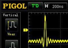
- PIGOL.JPG (21.63 KiB) Viewed 1264 times
PIGOL.JPG
I’ve just received mt encoders and I’m going to work on mt vision of the encoder option.
I think that using the touch ou such a small screen is not very practical…
But I will test with two encoders next year.
FINALLY got my screen after two months and uploaded a working version of the oscilloscope. Hooooooowever if I try to change the settings (over the Arduino serial monitor) nothing happens. Could it perhaps be that I’m usb to TTL to upload and read from the STM32? (I’m using one that looks like this http://www.ebay.com/itm/Replace-Pl2303- … SwHaBWi4TV )
I have it hooked up to PA9 and PA10 to upload the data (and later read it), with normal sketches at least. With the oscilloskope sketch, I get nothing on the Serial monitor, but the oscilloscope itself (aka display) seems to be working properly.
I’ve only tried the original version without the rotary switches.
Does anyone know how to solve my problem? Also…should I just buy some rotary switches and hook it up that way? How’s the speed on that version (and also bugs?)
I make a ne version, changing functions with two switches (interrupt) and parameters with one rotary encoder.
I have at the moment realized it for function timeBase (=1) and yPosition(02).
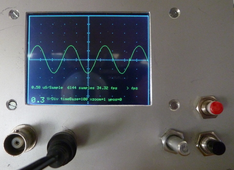
- P1020605.JPG (100.16 KiB) Viewed 1213 times
I have changed the code a liitle bit, I think there was to much code in the isr-functions.
Now the isr and the encoder-functions are smaller, I moved the tft-code on the start of the loop().
And changed the tft.text-size to 2.
And have some more functions realized !
If there are some errors, perhaps it is because of the short night (from 3 to 8) ![]()
- STM32-O-Scope-10.ino
- (32.38 KiB) Downloaded 75 times
textsize(2) for update-fields:
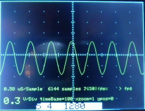
- STM32_O_Scope_func_par_txt(2).JPG (117.72 KiB) Viewed 1379 times
Edit: and, here is some new toy I got to play now
http://bildites.lv/a/sn5wkzax#ers3t9uf
http://bildites.lv/a/7npmye3q#ytm6u5ku
Happy New Year greetings to Wuppertal, I stood there in early October, only for a few hours.
I think the switches are old, but can be mounted easily.
I have a SW-debounce in the program too, but I think in the isr it’s not so good to wait long…
Furthermore encoder and switches are workings with isr and not with polling (I don’t know how touch / URtouch works).
I’ve added the decoupling capacitors (tried 1uF and 100nF) and I’ve seen more bouncing noise with the 1uF on the rising edges probably due to the slow rising time.

I’m trying the interrupt approach. Added one interrupt to each falling edge of each pin.
The issue is that I get false triggers on the noise from the rising edges.
And due to the fast refresh speeds I get lots of pulses from this noise…
Any ideas?
I might try mausi_mick’s encoder code (haven’t done it yet… ![]() ) to see if there’s any improvement.
) to see if there’s any improvement.
Also working on a new layout ![]() pictures latter on
pictures latter on
Also working on a new layout
I have only 10 nF ceramic directly on the encoder-pins, on the switches/buttons I have a RC-combination:
On the Input-Pin ST32F103 a 100nF (and a 1 µF (only for test)) and a 4.99 kOhm between Stm32F103 Pins and the switches.
But for the encoder I have changed the code a little bit :
void encCnt() {
if (s_enc == 1) return;
if (digitalRead(encA_16) && !digitalRead(encB_17)) {
if (encoderpos < maxp[actFunc]) {
encoderpos++;
actPos = encoderpos;
s_enc = 1;
}
}
if (digitalRead(encA_16) && digitalRead(encB_17)) { // subtract 1 from count for CCW
if (encoderpos > minp[actFunc]) {
encoderpos--;
actPos = encoderpos;
s_enc = 1;
}
}
if (s_enc == 1) setValue(actPos);
}
The encoder-counts are limited with the SW dependent of the function over a table:
//#######################################################################################

// functions:

//

//=========== functions ===============================

// 6 - Triggertype:  ---------------------------------6

// 5 - Triggervalue/position ----------------------5  |

// 4 - xZoomfactor ----------------------------4   |  |

// 3 - yZoomfactor ------------------------3   |   |  |

// 2 - yPosition -----------------------2  |   |   |  |

// 1 - timeBase----------------------1  |  |   |   |  |

//                                   |  |  |   |   |  |

//                                   V  V  V   V   V  V

volatile int16_t fold[8] =       {0, 1, 2, 3,  4,  5, 6, 0}; // old values

volatile int8_t const maxp[8] =  {0,19,13, 2, 19, 15, 2, 0}; // max. switch positions

volatile int8_t const minp[8] =  {0, 0, 1, 0,  0,  0, 0, 0}; // minimal switch position

volatile int8_t const stpw[8] =  {0, 1, 1, 1,  1,  0, 0, 0}; // step-width (not used)

volatile int8_t curp[8] =        {0, 1, 6, 1,  0,  6, 0, 0}; // current switch position

volatile uint32_t const  t_time[20] = {100,200,300,400,500,600,700,800,900,1000,1100,1200,1300,1400,1500,1600,1700,1800,1900,2000};

volatile int16_t  const  t_ypos[13] = {-240,-200,-160,-120,-80,-40,0,40,80,120,160,200,240};

volatile uint32_t const  t_triv[16] = {256,512,768,1024,1280,1536,1792,2048,2304,2560,2816,3072,3328,3584,3840,4096};

volatile int16_t  const  t_trty[3]  = {0,1,2};

volatile int16_t  const  t_yzfa[3]  = {100,200,300};

volatile int16_t  const  t_xzfa[20] = {1,2,3,4,5,6,7,8,9,10,11,12,13,14,15,16,17,18,19,20};  // ???
volatile uint8_t s_but_18=0; // 0=function fixed, 1=decrement function
volatile uint8_t s_but_19=0; // 0=function fixed, 1=increment function
volatile uint8_t s_enc = 1;
//############################################################################################################
The delay I have reduced to 0.
The montage is yet provisional . ![]()
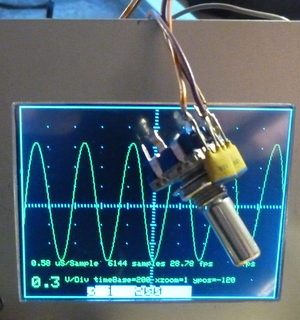
- P1020612.JPG (64.96 KiB) Viewed 1312 times
Here the video :
the newest source:
- STM32-O-Scope-11.ino
- (31.75 KiB) Downloaded 102 times
The encoders I used (on various projects) have a push button function as well.
I depending on what functionality you want, you could probably use the same encoder for sensitivity and also for vertical position, depending on whether the button was pushed in as it was rotated, and then just use the other encoder for timebase, and possibly for function selection if it was pressed in while rotating.
I tested it also with one Encoder and the integrated push-button,
but I think for the service it’s easier with two encoders, one for the “functiuon” : 1=timeBase, 2=yPosition, …6)
and the other for the “parameters” inside the function (different positions, for example triggerType only 3 (0,1,2) , for timeBase 15 … 30, how you like).
In program version 11 I don’t need any push button.
The encoders I used (on various projects) have a push button function as well.
I depending on what functionality you want, you could probably use the same encoder for sensitivity and also for vertical position, depending on whether the button was pushed in as it was rotated, and then just use the other encoder for timebase, and possibly for function selection if it was pressed in while rotating.
Would this be a sort of Bluetooth scope with the display via iOS or Android ?
Or would it still retain the display ?
I have tested it with one encoder in pgm-version 6, but I had made it their in three steps, that was really not comfortable.
Now I have changed it like your version, it’s easy use .
But I think the push-button (in the encoder) is not so good like the encoder-switches, he needs more time for debounce (about factor 10).
I’ve encounter this thing which is in a good price range and it’s the “same” as we are doing here… sort of….
https://pt.aliexpress.com/item/Digital- … ryId=50502
I have solved it a little bit other because I show the new functions/parameters on the display direct behind loop()
void loop()

{

// last_time = micros();

if ((s_encp == 1) || (s_encf == 1) || s_sw >= 1) {

showEncVal();  // display encoder values

}
and in showEncVal() I insert a delay(150) if the button is touched:
I’ve encounter this thing which is in a good price range and it’s the “same” as we are doing here… sort of….
https://pt.aliexpress.com/item/Digital- … ryId=50502
I’ve encounter this thing which is in a good price range and it’s the “same” as we are doing here… sort of….
https://pt.aliexpress.com/item/Digital- … ryId=50502
As Andy has shown, brilliant software can turn a demonstration device into a really useful tool. His Pig Scope software advances the useful characteristics far beyond a classroom demonstration.
But I find little value in discussing morphing the scope beyond the $10 range since cheap Chinese hardware is designed in a dedicated manner. I think taking Andy’s code and replacing the firmware of the Chinese scope is interesting, but I am not certain that any real value is going to be gained … an interesting rainy-day project, perhaps: use ArduinoIDE and the STM32duino F1 core files to reprogram the Chinese scope.
Anyway, perhaps such discussions are best moved to their own home topic since they are not in the spirit of the $10 Scope.
Ray
Oh, and I still need to make some off-topic post about list of DIY scopes besides O-Scope,that I have my eyes on. But here is short insight:
http://bildites.lv/users/ThunderJuris/albums
https://github.com/pingumacpenguin/STM32-O-Scope
Its a fun little project and well worth building just for the entertainment value. Currently bandwidth is a little limited, but with a little extra effort it would be possible to make a fully functional 2MHz Scope for next to nothing. Ideal for probing i2c, audio and other low speed signals.
Andy are you still maintaining the GIT on this?
UTouch has changed the name of the Library and
#include <URTouch.h>

URTouch  myTouch( PB12, PB13, PB14, PB15, PA8);

#endif
UTouch has changed the name of the Library …
https://github.com/pingumacpenguin/STM32-O-Scope
Its a fun little project and well worth building just for the entertainment value. Currently bandwidth is a little limited, but with a little extra effort it would be possible to make a fully functional 2MHz Scope for next to nothing. Ideal for probing i2c, audio and other low speed signals.
Andy are you still maintaining the GIT on this?
UTouch has changed the name of the Library and
#include <URTouch.h>

URTouch  myTouch( PB12, PB13, PB14, PB15, PA8);

#endif
And with a small modification (function 7: set frequency AD9851) I can set the frequency of the AD9851
and display it on O-Scope:
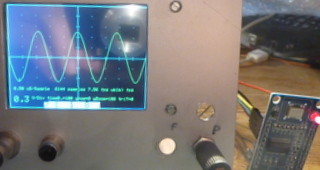
- P1020613.JPG (31.06 KiB) Viewed 1326 times
And with a small modification (function 7: set frequency AD9851) I can set the frequency of the AD9851
and display it on O-Scope:
- STM32-O-Scope-AD9851_00.ino
- (33.92 KiB) Downloaded 213 times
And with a small modification (function 7: set frequency AD9851) I can set the frequency of the AD9851
and display it on O-Scope:
P1020613.JPG
Edit:
mausi_mick and anyone else who used such generator modules (from “usual sources”, I suppose), a question – are they allright? I ask because chips are most likely chinese copies, am I right? Usually common sense goes like this: digital ICs copies are okay, but analog IC devices better buy form official sources. So, do these chinese generator chips work okay? Thanks.
So, do these chinese generator chips work okay? Thanks.
It’s from the example in URTouch-Lib. If you rotate with the encoder to function 7 (DDS-Frequency) and select parameters, the display changed to touch mask. You can type in the frequency and touch the “ENTER” button,
the osci shows the Sinus – Function with this frequency:
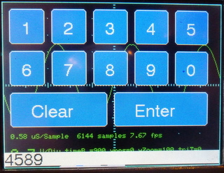
- P1020614.JPG (55.74 KiB) Viewed 1270 times
I think the modules are ok for hobby, I have one with AD9850 on an Arduino Nano with frequency counter (10 Hz … 4MHz).
On the picture its on the bottom of the display. On the right you can see the step width (changing with the red and green buttons) for the rotary encoder.
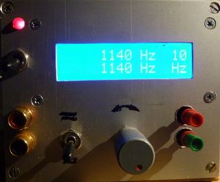
- P1020618.JPG (54.41 KiB) Viewed 1265 times
But I think perhaps we need far reaching goals like
– second channel
– speech command …
I have tested it a little in the early eighties on Sinclair ZX80, but no real success.
Only for numbers, but I had problems to differentiate words with similar phoneme like 2 and 3( in german language “zwei” and “drei”).
But it was a slow processor with 1 kB Ram, and micro- Input over the socket from music cassette (as “floppy” compensation).
Position p=1: no Signal (default)
Position p=2,3,…255 f(AD9851) = (p-1) x 1 kHz
Position p=0: switch to touch-screen, return with “ENTER”, f = input digits in Hz
if you want to switch off the signal, it’s only possible via the touch-panel.
here the code:
- STM32-O-Scope-AD9851_01.ino
- (40.81 KiB) Downloaded 47 times
P.S.: for curious here is a link
https://yadi.sk/d/QJmF7P2byAYma
You found this code!!! I’ve been searching for it
It was in a post from you (I think ![]() ) where you posted some pictures of it and some more scopes (ThunderJuris) precisely that last link
) where you posted some pictures of it and some more scopes (ThunderJuris) precisely that last link ![]()
Then I was trying to get the code to get “some ideas” but couldn’t find anything. And then BAM! you post this ![]()
My antivirus blocks the link cvs.aiq.ru saying it’s dangerous ![]() I’ll maybe try with it off for a second lol
I’ll maybe try with it off for a second lol
// Additional  display specific signals (i.e. non SPI) for STM32F103C8T6 (Wire colour)

//#define TFT_DC      PA0      //   (Green)  11 maple mini

//#define TFT_CS      PA1      //   (Orange) 10 maple mini

//#define TFT_RST     PA2      //   (Yellow)  9 maple mini
//#define TFT_DC PB4 // (Green) 18 maple mini
//#define TFT_CS PB3 // (Orange) 19 maple mini
//#define TFT_RST PA15 // (Yellow) 20 maple mini
#define TFT_DC PA15 // (Green) 20 maple mini
#define TFT_CS PA14 // (Orange) 21 maple mini
#define TFT_RST PA13 // (Yellow) 22 maple mini
I think the program loops in the trigger-routine.
If I put a signal on the input-pin, the program starts direct.
With the intern DDS generator and an external generator I made some pictures:
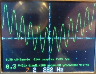
- STM32_O_Scope_Sinius_222Hz_3kHz.JPG (52.61 KiB) Viewed 1323 times
I think I have this board:
http://www.ebay.de/itm/AD9851-DDS-Signa … SwImRYWB6B
It has a dimension from 2.5 cm x 4.5 cm, the holes have a distance from about 2 cm x 4 cm.
The 0 to 1 MHz square-signal I haven’t seen (no jumper on board ?).
Perhaps you / I have to look in the datasheet.
I use the serial port for setting frequency.
It has a dimension from 2.5 cm x 4.5 cm, the holes have a distance from about 2 cm x 4 cm.
If you switch (with the button on the encoder) to function, the first number (for function 1…7 = timeBase … AD9851)
is red illuminated, if you touch again, the second number (for parameters) is yellow illuminated. The third number shows the current value of the parameter.
To test, I’ve just loaded the AnalogReadSerial example and it works fine: Win10, 72MHz, Boot0 is 1 for programming, 0 otherwise. I’ve tried with serial_debug.begin(115200) and it doesn’t work for me but serial_debug.begin() works. Arduino 1.8.1.
Also, not sure what’s up with these boards or the bootloader but on initial power-up Windows reports USB device not recognized. Since I’m using a powered USB hub I just disconnect the USB from computer (while board remains under power) and then it get recognized. Perhaps I’m missing something or I should be flashing another bootloader. I just used the board as-is and it seems to be working fine otherwise.
BTW, after the device is successfully enumerated, with a basic example the baud rate is ignored and auto-negotiated by Windows, so it does not matter what baud rate you select. Using RealTerm for debugging. I can use Linux (either VM or standalone) but I feel something is off.
Offtopic, but there is a syntax error in the latest source code from GIT:
-#if defined TOUCH_SCREEN_AVAILABLE
should be:
+#ifdef TOUCH_SCREEN_AVAILABLE
unless I’m also missing something there.
Success! I got serial interaction working, with default USB “Maple serial” port (onboard USB socket). Problem was one line, that is present in original github INO file, and also later in INO file for fancy miniature TFT. This line (under “void setup”):
serial_debug.begin();
To get my serial working, I have to make it like this:
serial_debug.begin(115200);
or, even comment it out altogether works, for some magic reason!
-#if defined TOUCH_SCREEN_AVAILABLE
should be:
+#ifdef TOUCH_SCREEN_AVAILABLE
unless I’m also missing something there.
My main goal is to have it output data on serial (as written some pages ago) so I’ve commented out most of the touch and LCD code. Now that I’m thinking more, perhaps it’s hanging in some LCD init function.
Edit: haven’t seen all the posts, was not aware that “#ifdef” is the same as “#if defined”.
Looking into the USB hardware issue now as well.
However I have to ask this in a separate post: does not having an LCD alter the flow somehow? i.e. is SPI waiting for some commands that are not arriving? Should I worry about that or did someone already test it without an LCD connected?
I’ve ‘commented out’ the RTC lines through some preprocessor behavior as I want this to be as self-contained as possible (minimal hardware):
#ifndef RTC_AVAILABLE

int hour(long time){return 0;}

int minute(long time){return 0;}

int second(long time){return 0;}

int day(long time){return 0;}

int month(long time){return 0;}

int year(long time){return 0;}

void setTime(int time){}

long now(){return millis();}

#endif
http://bobdavis321.blogspot.de/2013/06/ … s-per.html
…
but back to O-Scope:
I had problems with the AD9851 to set back to 0 Hz, it needs more than 400ms.
Therefore I changed the code and reset/init the AD9851 in this case. It’s stable and quicker.
How quick and comfortable you can change frequency you can see on the video:
[urlhttps://youtu.be/g8Aow6RRULM][/url]I think the program loops in the trigger-routine.
If I put a signal on the input-pin, the program starts direct.
STM32-O-Scope-AD9851_01.ino
thanks for the code,
I have set triggerSensivity to 100 ?? ( 10 was to small) :
uint32_t triggerSensitivity = 100; //########################## ????????
and changed in the function …triggerBoth()
the “or” in the code to || .
I think it’s starts now quick, but for the sinus-wave I think it’s triggered (with triggerBoth()) not stable.
That approach using triggerSensivity is not ideal because you won’t have a stable trigger. It may work ok for a sine and other similar waves but for other signals it won’t work as expected.
And on that code you can’t set a trigger value.
Just to be clear: 72MHz, Boot0 set to 1 while programming, 0 when booting, programming via serial. Is this correct?
If I leave serial_debug.begin() as is I first need to power the board, then connect it to USB, otherwise I get ‘unknown device’. The PC13 led blinks about 5 times/second (trigger?), I can connect to the usb serial port, type ‘s’ but nothing get received. If I type ‘h’ I expect the blinking to stop but it doesn’t. So no reply from the USB serial port.
If I do serial_debug.begin(115200) the PC13 remains lit at all times after booting, usb serial is not recognized. Same thing happens if I switch the frequency to 48 MHz.
Just to be clear, trying a simple sketch with usb serial output works.
I will try putting all TFT- and SPI-related code into #ifdef blocks.
Edit: it’s related to the serial USB (CDC) port, somehow it’s not working. Not sure what to do, I have the same problem on both boards. Driver related? Should I flash another bootloader?
Thank you! That did the trick, I was using the github bootload prior to this.
I still have to power the board first then plug USB (or reset board, disconnect hub from computer, reconnect to computer), but it’s a minor annoyance.
I mean – what are your thoughts, is this addition good enough, or maybe not worth it? I don’t know quality of those modules, is it worth those about 12 dollars? Simply your personal thoughts, please
I think it’s ok for this price, but I haven’t found detailed info to the board or a schematic.
Their a two sinus outputs and two for square-wave (0-1Mhz), but no signal on it ?
I want to generate from the sinus other signal-forms with a schmitt-trigger (and integrator ?).
Here I found more infos to the AD9851:
For low frequencies you are better off using your phone or a computer. For low-medium frequencies I bought a FY3200S for ~70$. For anything else the only affordable option is second-hand lab gear.
The DDS module is just a toy, fine if you want to play and figure out how DDS works and its limitations. It will also output a useable low-level signal if you give it the right input and the stars align. To improve it you need a strong LP filter (for sine waves) like in the linked article and a well-designed output buffer.
Just my 2c.
Some tutorials suggest you better use some higher quality external comparator to form square wave, if needed.
with the HC14 it’s ok for lower frequency (20MHz?), but you have something to do with the duty ratio:
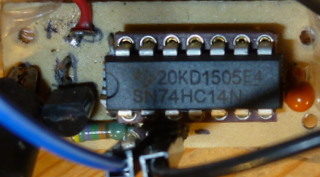
- ST M32_O_Scope_AD9851_HC14_Schmitttriger.JPG (37.76 KiB) Viewed 1501 times
I just found another one, and it is STM32, and really simple and interesting – I am definetely going to build it! Well, not much to actually “build” there, really. It is this one in list:
S-14-(RU) STM32F103, Bluetooth, Android, Windows
https://www.youtube.com/watch?v=dQIyseS2jts (corrected wrong link, good now)
http://forum.easyelectronics.ru/viewtop … 17&t=27404
Archives in forum has schematics, ready .HEX, ready .APK, ready Windows .EXE
Last forum entry is october 2016, so now I am going to join a discussion, say “Boljshoe Spasibo”, and ask is there advances planned, and maybe sources shared. There is one important thing that we (O-Scopists) could adapt from that device: input stage with cheap programmable gain OpApm (MCP6S21). Other opamp (any Rail-to-Rail) in that schematics is for moving displayed graphic up/down.
Well, I am exited about this finding. Gonna try it very soon. And looks like I really need some DDS module(s)…
EDIT jaunary 22:
My initial tests, without input circuit:
http://bildites.lv/a/7cup2kep#2k6sm4rg
tested on two different china STM32 modules (shown in pics)
I have that MCP6S21/2 addition in my “to-do” list already ![]() but still to do…
but still to do…
I’ve finished a scope based on the original stm32-o-scope and it works great! However, I’d like to know how to implement frequency measure, so we could see both waveform and frequency. Any ideas?
Maybe you will need to average that value and refresh display of that value only once in while in case it is drifting too much, otherwise, it will be difficult to read.
If you want a little light bed time reading ![]() ->
->
https://en.wikipedia.org/wiki/Hilbert%E … _transform
https://en.wikipedia.org/wiki/Fourier_transform
https://en.wikipedia.org/wiki/Instantan … _frequency
If you want a little light bed time reading ![]() ->
->
https://en.wikipedia.org/wiki/Hilbert%E … _transform
https://en.wikipedia.org/wiki/Fourier_transform
https://en.wikipedia.org/wiki/Instantan … _frequency

Oh, and for those who were following similar projects (to get inspirations and what not) – there is a new thing going on from user “GFX”, scope v3.0 (forum radiokot.ru). Tkae a look, if interested. Materials are in “GFX” user’s signature link.
I’ve been working on the changes I’ve mentioned before.
They are quite a few and I haven’t been able to move as fast as desired but I’ve been moving forward.
Probably this weekend I’m going to be able to work on this and release a working version with most of the functions.
I’m using a single encoder and I think it will be enough but maybe 2 or 3 would be more “user friendly” ![]()
As for construction, it’s still not “enclosured” yet ![]() unfortunately…
unfortunately…
“GFX”? I’ll check it out ![]()
here is the status ![]()
Working (reasonably ![]() ) :
) :
– menu navigation
– menu values changing
– trigger edge (but the waveform doesn’t change accordingly! lol must take a look into this maybe with a sinus wave)
– trigger level (values from 0 to 4096.to be corrected to volts later)
– trigger level indication!!!! (that red trace on the left of the wave ![]() . have to change it to an arrow or something)
. have to change it to an arrow or something)
Implemented but still not tested:
– trigger mode (Auto, normal, Single)
– Run/Stop
– timebase scale (modified to show “50us”…”100us”…”1ms”, etc and reflect the real timebase ![]() )
)
– vols/div (modified to show “50mV”…”100mV”…”1V”etc only zoom factors. The MCP6s22 will come latter so will have to make some adjustments…)
Still to do:
– dual channel (on the way) (missing: ADC capture, drawing, 2nd channel trigger)
About that new version 3.0 (it is F407 based), by user GFX and friends:
https://www.youtube.com/watch?v=Y64b1HW … e=youtu.be
http://radiokot.ru/forum/viewtopic.php? … &start=820
https://yadi.sk/d/QJmF7P2byAYma
As announced before… here is a preliminary version of my approach of the STM32-O-scope.
– volts/div is still WIP. (is more like a zoom function…)
– dual channel is still WIP too.
I was faced with an unexpected issue with the vertical graticules as I thought I had 200pixels but it’s really 220 and the math is off a bit, using the present method.
So I’ll probably lower it to 200pixels and create a info area below (or above) the graph area.
- STM32-O-Scope-byRex-v0.9.ino
- (41.22 KiB) Downloaded 87 times
http://forum.easyelectronics.ru/downloa … &mode=view (part “1” of picture)
That lower opamp is used for moving signal up/down on the screen, Can be omitted, the C4 should be shorted. If this opamp is used, it can be any Rail-2-Rail.
I think that adding VCC/2 on that 100K resistor (where the opamp is connected) will allow us to have + and – voltage measuring instead of only positive.
So maybe this schematic can be of use ![]() Thanks!
Thanks!
It has an Android app and a PC version?
Edit: Just saw it, yep, I remember now ![]() looks good.
looks good.
From a fast search on uncle google:
http://www.analog.com/en/products/ampli … t-overview
It doesn’t have the 32 gain step but seems more or less usable in this purpose.
It doesn’t have the 32 gain step ….
Not a big problem I think.
Have you tried the Microchip $ample program and it failed or didn’t tried it yet?
All you have to have is a “non generic” mail address.
As announced before… here is a preliminary version of my approach of the STM32-O-scope.
Are you sure that SPI pins are the same?
I’ve changed those from the original ones, not sure if mausi_mick also uses this configuration… my guess is no.
They are all the same but the order is changed… ![]()
———————-Original:—————————-
// Additional display specific signals (i.e. non SPI) for STM32F103C8T6 (Wire colour)
#define TFT_DC PA0 // (Green)
#define TFT_CS PA1 // (Orange)
#define TFT_RST PA2 // (Yellow)
// Hardware SPI1 on the STM32F103C8T6 *ALSO* needs to be connected and pins are as follows.
// SPI1_NSS (PA4) (LQFP48 pin 14) (n.c.)
// SPI1_SCK (PA5) (LQFP48 pin 15) (Brown)
// SPI1_MOSO (PA6) (LQFP48 pin 16) (White)
// SPI1_MOSI (PA7) (LQFP48 pin 17) (Grey)
//
———————-Your INO:————————
// Hardware SPI1 on the STM32F103C8T6 *ALSO* needs to be connected and pins are as follows.
variants/generic_stm32f103c/board/board.h:#define
BOARD_NR_SPI 2
BOARD_SPI1_NSS_PIN PA4
BOARD_SPI1_MOSI_PIN PA7
BOARD_SPI1_MISO_PIN PA6
BOARD_SPI1_SCK_PIN PA5
BOARD_SPI2_NSS_PIN PB12
BOARD_SPI2_MOSI_PIN PB15
BOARD_SPI2_MISO_PIN PB14
BOARD_SPI2_SCK_PIN PB13
*/
// Additional display specific signals (i.e. non SPI) for STM32F103C8T6 (Wire colour)
#define TFT_DC PA2// PA0
#define TFT_CS PA0 // PA1
#define TFT_RST PA1// PA2
#define TFT_CS PA1
#define TFT_RST PA2
vs.
#define TFT_DC PA2
#define TFT_CS PA0
#define TFT_RST PA1
Look closely ![]()
Look closely
THANK YOU, Rexnanet.
THANK YOU, Rexnanet.
Yesterday I’ve been assembling the MCP6S92’s on a tiny breadboard….
But if you have one to test it’s great.
MCP6S61 doesn’t seem to exist ![]() Either MCP6S91 or MCP6S21
Either MCP6S91 or MCP6S21 ![]()
http://bildites.lv/a/684af4cb#4wns5ujq
(and some other show-offs – http://bildites.lv/users/ThunderJuris/albums , if bored, check Sharp TV re-make)
About this firmware of O-Scope – in my case, encoder manipulations are not very stable. I have resistors 10K from both encoder side-pins and switch pin – to +3V3. Btw, I initially had no resistor on switch pin, and that resulted encoder shaft being a sensor, and switching on touch (without that knob in pictures). Now switch is okay, but left-right is slightly with its own mind. Is that just my setup, or common problem?
Yes, the encoder is not very responsive. Has a bit of a mind of it’s own.
My encoder has 10k resistors to +VCC and I added 100nF capacitors to GND. (tried 1uF but was even worse)
The problem is that on the falling edge there’s no noticeable noise but on the rising edge there’s lots of it.
I tried to jump that noise by ignoring the pulses during some 4ms. But even so there’s an erratic behavior.
Might have to make a test code and debug using some pins and the logic analyser…
Or try another approach…
I’ll try a code that shows how many interrupts occurred and the time of each one to help diagnose the problem.
Is the encoder response from mausi_mick’s code ok?
But the refresh rate from his code is not so fast… that could influence this also.
” Scope, when you press the touch, ceases to do synchronization, it is intended so – to somehow respond to touch, so, quick, but without synchronization. In the high-frequency signal, you do not feel that, because there is also a software synchronization, but turning to time 1ms and a few times a second you will see that it starts to not work properly. The fact, that, for small scans by 40ms or more touch almost does not respond – it is a fact, but, what to do? Collect ADC buffer, or respond to touch? …” (from russian, “GFX”).
Even though there’s some boards on aliexpress around 14€… it’s not bad.
Touch is a bit tricky but this text suggest that they would benefit from interrupt driven ADC captures. Or using a timmer for those slow scan timings.
Oh, and I wanted to ask, wasn’t there possibility to activate internal pull-ups on those STM32 pins?
Using the falling edge to do the counting would help probably, but maintaining the rising edge discrimination time.
Only more testing will improve this… (time travel capsule needed
The resistors on the encoder are already pull-up’s don’t think the internal would do anything here…
The resistors on the encoder are already pull-up’s don’t think the internal would do anything here…
I have these:
https://pt.aliexpress.com/item/Free-Shi … 9342e4b279
Only had to add a resistor for the SW and added a capacitor on each one to GND.
Without capacitor : total caos ![]() I tested it on the logic analyser(saelae clone).
I tested it on the logic analyser(saelae clone).
There is a thread about debouncing those rotary encoders.
I use them myself, and use external CR debounce.
I use an external resistor and capacitor, but had issues with this. So I would advise using 2 external resistors and one capacitor. ( as discussed in the other thread)
BTW. I don’t think you need Schmitt triggers. the R,C,R external circuit was enough.
PS. dont try using the internal pullup ( like I did), as its value is defined in the spec to be something like 40k plus or minus 10k, which is too high not to be prone to glitches.
After all, there’s no multiple interrupt being generated on the Rising pulse edges. It was only observed on the logic analyser.
But I have false rising interrupts on the falling edges so I opted to use falling interrupts and now it’s very simple and minimalist (as it should have been from the start ![]() )
)
Working great now ![]()
Added the MCP6S92 code but still as a trivial demo. Cycles through all the gains so “volt/div” is not real. But proves the point.
Improved the trigger a bit. Trigger mode works better.
It’s enough for today ![]()
- STM32-O-Scope_byRex-v0.91.rar
- (11.37 KiB) Downloaded 115 times
Here, off-topic or not – what “our” almost zero price “BluePill” is capable of:
https://www.youtube.com/watch?v=7pFui4tvjBE&t=0s
True, this graphic awesomeness is on parallel TFT, not SPI (can we have version on parallel TFT?), but still, looks soooo sweeeet…
http://bildites.lv/a/daxkuzd2#8stbtwj7
If it looks like yours, I can point you to code, so probably you will see what libraries (what chipset) are used.
https://pt.aliexpress.com/item/3-2-inch … 19747.html
I have a Mega now (3d printer project ![]() ), probably it’s easier to test it on it…
), probably it’s easier to test it on it…
In the David Prentice TFT library there is a sketch capable of identify the chip in most of the cases.
http://bildites.lv/images/vf8ywtw5/19940/original.jpg
Well, it is not free samples (I did write earlier why), but still manufacturers prices with special offer – free shipping (with fast express).
If nothing else – I am kind of pretty sure, those are originals, not some re-marked chinese fakes
I am back , I was in holidays near the “antipodes” ? – in Srilanka, its’s really warmer at this time as the weather in Germany or in Lithuania !
I have the program with the AD9851 modified a little bit, and integrate the frequency-counter function (on PA15) from the forum. Therefore I have moved the display pins CD / CS to PA14 / PA13.
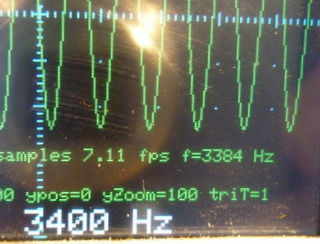
- STM32_O_Scope_AD9851_FreqCounter_PA15.JPG (47.08 KiB) Viewed 1509 times
BTW which is closer to the truth? 3384Hz or 3400Hz ? having said that… 99.529% accuracy ‘aint bad for us amateurs. ![]()
Hmm, I probably will need to make some jumpers in my construction, to be able to try andy’s, rexnanet, and your versions. Or, maybe make remap in INO files, to some unified connections to screen, encoder. Have to look into that.
I have heard for some times that the last 1% of accuracy cost more than 95% of money/time !
( I think it was for the accuracy of the tank Leopard). But now I have time ? ![]()
The accuracy of the counter was most better than 7 Hz, but at some frequency (3000Hz -> 3095, 5000 Hz -> 4762, 7000Hz -> 7205, 9000Hz -> 8538…)
the error was very big.
I think it was a problem with the AD8951, perhaps with the generated frequency from 180 MHz at 3.3V.
I changed the SW:
http://www.changpuak.ch/electronics/AD9851.php
and modified it a little bit (DDS_CLOCK 120MHz) …
Now its work stable with an error less than 1 Hz until 10 kHz and 7 Hz until 300 kHz.
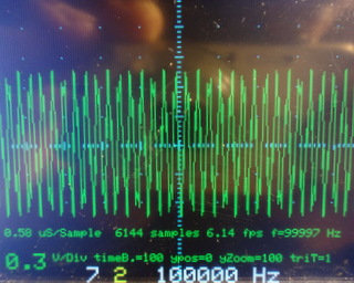
- DSC00012.JPG (59.11 KiB) Viewed 1467 times
the different Pins could be a problem, I have changed it partly for shorter wires, or save pins (e.g. for restart PIN on 3.3V).
Another problem is that not all pins of the STM32F103 chip are connected to the board, neither on the blue pill nor on maple mini:
on maple mini for instance their is no PIN for PB9, which needs Rexnanet for the encoder-buttom.
I try to test his(Rexnanat) program for the MCP6S92 … and I hope, that it would soon go on with the second channel …
it’s possible to change the Landscape -format to Portrait,
than we could display the Signal with full 8 bit resolution (256) in the high and had place for scope-settings (delay, trigger, …) in a own in the 84 x 240 field on the top or on the ground ?
it’s possible to change the Landscape -format to Portrait,
than we could display the Signal with full 8 bit resolution (256) in the high and had place for scope-settings (delay, trigger, …) in a own in the 84 x 240 field on the top or on the ground ?
I think with the 8 bit it’s difficult too, because the MCP6.. has only 1% accuracy and you have to select other components to better than 0,5 %.
And I think better than 7bit it’s for hobbyist enough . ![]()
This way we can simply set the variable we want and that’s it ![]()
What do you think?
That sounds smart to me. What others say?
but I think a Scope is more for the signal form etc, not for the accuracy ( if the amplitude is 2.5V or 2.516 V) .
but I think a Scope is more for the signal form etc, not for the accuracy ( if the amplitude is 2.5V or 2.516 V) .
My original development was on Bluepill, so the codebase can be adapted to work with generic F103 boards.
I will start another thread for that.
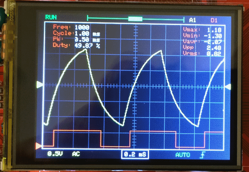
- pic2.png (164.74 KiB) Viewed 1752 times
My original development was on Bluepill, so the codebase can be adapted to work with generic F103 boards.
I will start another thread for that.
and the SW is very good structured !
I tried to change it to maple mini and to the SPI-TFT-Display ILI9341:
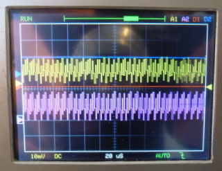
- STM32-O-Scope_DSO-138.JPG (51.33 KiB) Viewed 1713 times
Please add the link here later.
But this version uses a parallel display right?
and the SW is very good structured !
I tried to change it to maple mini and to the SPI-TFT-Display ILI9341:
STM32-O-Scope_DSO-138.JPG
But I have only changed at this time the Display-Pins ( CS,RST,DC,CLK) and the pins from the encoder.
To move the ADC Inputs (PA0 , PA4) is for me difficult or impossible , because their is something written in assembler.
But I think I have to take an second STM32F103 …
and the SW is very good structured !
I tried to change it to maple mini and to the SPI-TFT-Display ILI9341:
But I have only changed at this time the Display-Pins ( CS,RST,DC,CLK) and the pins from the encoder.
To move the ADC Inputs (PA0 , PA4) is for me difficult or impossible , because their is something written in assembler.
But I think I have to take an second STM32F103 …
I had a some problems to make the program stable, I have to change a lot of pins, and some pins must be pwm-Pins.
Now I have PA4 free for SPI and the analog Inputs are on PA0 and PB0.
It’s not much work,
– delete complete src lib in the download DLO-138
– change the libs in Adafruit… in DLO-138.ino and insert <SPI.h>
– change in display.ino :
Adafruit_ILI9341_STM tft = Adafruit_ILI9341_STM(TFT_CS, TFT_DC, TFT_RST); // Using hardware SPI
//Adafruit_TFTLCD_8bit_STM32 tft;
– delete their tft.reset() and change tft.begin(0x9341) to tft.begin
– change the global.h (different maple/blue-pill)
here my maple-global h:
// comment out following line to use DSO push buttons instead of encoder

#define USE_ENCODER
// serial print macros
#define DBG_INIT(...) { Serial.begin(__VA_ARGS__); }
#define DBG_PRINT(...) { Serial.print(__VA_ARGS__); }
#define DBG_PRINTLN(...) { Serial.println(__VA_ARGS__); }
#define SERIAL_BAUD_RATE 115200
// analog and digital samples storage depth
#define NUM_SAMPLES 2048
// TFT_SCK PA5 // D6 #####
// TFT_MOSI PA7 // D4 #####
#define TFT_CS PA4 // D7 ##### PA14 // PA14 D21
#define TFT_DC PA15 // D20 #####
#define TFT_RST 112 // 112 ##### //PA13 // 3.3V
// display colours
#define AN_SIGNAL1 ILI9341_YELLOW
#define AN_SIGNAL2 ILI9341_MAGENTA
#define DG_SIGNAL1 ILI9341_RED
#define DG_SIGNAL2 ILI9341_BLUE
// pin definitions (DSO138)
#define BOARD_LED PC13 // D14 ##### PA15
#define TEST_WAVE_PIN PA9 // D26 ##### PA7 D4 // PWM 1KHz square wave output
#define TRIGGER_IN PA8
#define TRIGGER_LEVEL PB8
#define VGEN PA10 // D25 ###### PB9 // used to generate negative voltage in DSO138
// captured inputs
#define AN_CH1 PA0 // D11 analog channel 1
#define AN_CH2 PB0 // D3 ###### //PA4=D7 // analog channel 2
#define DG_CH1 PA13 // digital channel 1 - 5V tolerant pin. Pin mask throughout code has to match digital pin
#define DG_CH2 PA14 // digital channel 2 - 5V tolerant pin. Pin mask throughout code has to match digital pin
// misc analog inputs
#define VSENSSEL1 PA2
#define VSENSSEL2 PA1
#define CPLSEL PA3
// switches
#define ENCODER_A PB3 // D19 ##### // PB13 //##################################
#define ENCODER_B PB4 // D18 ##### // PB14 //##################################
#define ENCODER_SW PB5 // D17 ##### // PB12 //##################################
#define BTN4 PB6 // D16 ##### // PB15
/*
// switches
#define ENCODER_SW PB12
#define ENCODER_A PB13
#define ENCODER_B PB14
#define BTN4 PB15
*/
// TFT pins are hard coded in Adafruit_TFTLCD_8bit_STM32.h file
// TFT_RD PB10
// TFT_WR PC15
// TFT_RS PC14
// TFT_CS PC13
// TFT_RST PB11
// FLASH memory address defines
#define PARAM_PREAMBLE 0
#define PARAM_TIMEBASE 1
#define PARAM_TRIGTYPE 2
#define PARAM_TRIGDIR 3
#define PARAM_XCURSOR 4
#define PARAM_YCURSOR 5 // 5,6,7,8 - 4 params
#define PARAM_WAVES 9 // 9,10,11,12 - 4 params
#define PARAM_TLEVEL 13
#define PARAM_STATS 14
#define PARAM_ZERO1 15
#define PARAM_ZERO2 16
#define LED_ON digitalWrite(BOARD_LED, LOW)
#define LED_OFF digitalWrite(BOARD_LED, HIGH)
// number of pixels waveform moves left/right or up/down
#define XCURSOR_STEP 25
#define YCURSOR_STEP 5
#define BTN_DEBOUNCE_TIME 350
Or is it to quick ?
Than I need only one Pin for CS_MCP6Sx
The driver already has HW-SPI option but I haven’t tested it yet.
In theory it would be possible as long as the SPI speed is reconfigured every time the MCP is accessed.
Today I did some fancy thing I was planning for some time. Replaced chip on one of my “BluePill” boards with STM32F303 microcontroller.
Sure I am not the first one doing that, I know. Many have thoughts that would be nice if chinese manufacturers would make cheap “F303 Pills”, but there are none (AFAIK). So, we can make one, pinouts are the same as F103. Here my pictures:
http://bildites.lv/a/pjuhvaf5#6jv5nwen
One of pics shows this board running tomeko.net “MiniScope v2d” firmware.
I thought, maybe that is something to consider here in our “O-Scope” variations. If someone write code for F303 (better ADCs, etc), with such BluePill conversion we have “drop-in, pin-compatible” hardware.
Technically, I did “blow off” old chip with hot air pistol, and soldered STM32F303CBT6 in place.
Thoughts, anyone?
I was thinking the same… replace the chip on the blue pill.
But isn’t the code from GFX better for this purpose? It’s already functional right?
I was thinking the same… replace the chip on the blue pill.
But isn’t the code from GFX better for this purpose? It’s already functional right?
GFXscope version v2.0 (F303 based) is not free. Well, for me it is, cause I bought “rights” to v3.0 firmware, and v2 comes as a bonus, if needed. But it is impossible to “borrow” to someone (even if I would want to), they are particular chip locked. But, yes – if you have bought v2.0 firmware, then such “BluePill Pro” makes easier to experiment.
have you seen the GD32BluePill (with 120MHz) :
have you seen the GD32BluePill (with 120MHz) :
have you seen the GD32BluePill (with 120MHz) :
to the GD32F103 “Bluepill” exist a schematic:
- GD32F103C8T6_CoreBoard(New_Version).pdf
- (52.24 KiB) Downloaded 176 times
The issue was that it was jumping to “normal” trigger and it stopped (it’s a bug because it should run because it had valid trigger but…
If you go to the trigger menu and select “auto” it runs ok.
I’ve tested the 2 MCP6S in series and it’s running ok too. Still have to check if the gain settings are ok but they are working.
Noticed that at max gain the second MCP6S rises the GND level a bit. Maybe there’s an offset issue somewhere… but don’t have a scope to measure it ![]()
Here’s the code if someone wan’t to test it:
- STM32-O-Scope-byRex-v0.92.rar
- (11.81 KiB) Downloaded 158 times
About DDS option(s), I have module with ADS9833 chip (not 9850/51), I think it has SPI control. I wonder if that will work with upcoming code too, hmm. Did not order ADS9851 yet, maybe later…
MCP6S92_A1_CS PA9
MCP6S92_A1_DIN PB10
MCP6S92_A1_CLK PB11
MCP6S92_A2_CS PA10
MCP6S92_A2_DIN PB10
MCP6S92_A2_CLK PB11
Others are +3.3V, GND and Vin and Vout…
Meanwhile, I’ll try to draw something.
thanks for the code.
at present I am testing the amplifier hardware, a mixture from DSO150 reducer and an amplifier with MCP6S91.
I have some problems with noise , therefore I have to shield it. For the negative supply-voltage I take a MAX660 , its’ better than ICL7660 ( smaller R-on and higher switch frequency (about 80kHz)).
For the AD9850 exists a SPI-Lib for Arduino UNO, but I think we have it to modify …
Why are you using negative supply rails?
MCP6S is only positive supply if I recall. I’m going to add VCC/2 on an input amplifier so that it can accept negative voltage and be already in the ADC voltage range.
Might have a few drawbacks but it’s simpler in other aspects.
I know it, it must be easier, but I tried to copy the reducer from DSO150 only with little changes:
Separate switch for AC/DC and C for max 230-50V AC, in the first stage bigger distances between the components and in the divider 2 resistance for one ( because of the electric strength ![]() ) .
) .
A video with the preamp in action is here:
I’ve seen the video before the post ![]() It’s running great. except near the end
It’s running great. except near the end ![]() what happened?
what happened?
Now the shielding of the preamp is better:
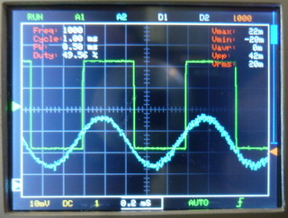
- DLO138-SPI_Display_shielded_preamp.JPG (57.71 KiB) Viewed 1424 times
The noise levels seem ok. Are you using a breadboard or have you made a board for it?
The need for shielding might indicate some ground problems or too much attenuation+gain…
Now you could make some measures to see if the voltage levels match the real signal ![]()
IMO you could also make the videos a bit longer ![]() it’s nice to see it in action
it’s nice to see it in action
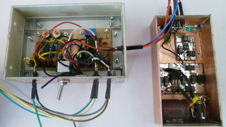
- DLO138-SPI_Display_Preamp.JPG (46.18 KiB) Viewed 1418 times
Thanks
Thanks
DLO138-SPI_Display_Preamp.JPG
I have made a new video (with better Sinus over divider (10k/3.3k) and changing gain of MCP6S91 between 1 … 8).
https://www.youtube.com/watch?v=GRtzcdL … load_owner
the MAX660.
There are 3 connections to the preamp for -5V, 0V and +5V.
On the left is a input-stage similar DSO150 with an TLC072 and on the right a MCP6S91
and an amplifier / levelshifter from -5V …+5V to 0V…+3.3V
http://bildites.lv/a/xfjbphbf#33yk2zed
Project forum here:
http://forum.easyelectronics.ru/viewtop … 4&start=75
On the screen ( bottom right) is now a second touch-field to activate the amplifier.
The signals are from external generators.
The video is on Youtube:
is it somethimng like this:
what will You make with the HC05/HC06 ?
what will You make with the HC05/HC06 ?
what will You make with the HC05/HC06 ?
Do You transfer the scope-data via bluetooth to android to display it there ?
It’s quick enough ?
something other, you asked for AD9850/51 connected with SPI. I have tested it , but not with success. It was possible to generate a frequency and I can see it on the screen, but if I try to change the frequency their is chaos . Sometimes appears a very high frequency and if I try to set to 100 Hz, he gives a very low frequency back. I tested some diffent software (from Arduino), but I think it’s difficult to transfer the frequency order.
Perhaps other have more success, but I stopped it.
Now I try to integrate the two amplifiers in the scope:
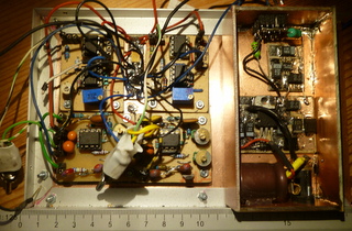
- DLO138-SPI_Display_Preamp_2.JPG (57.99 KiB) Viewed 1835 times
I had problems with SPI for ADS9851, but now I need only three Pins , I put Pin AD_RST to ground.
Now I have installed the two preamps:
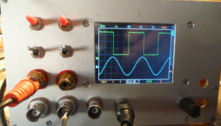
- DLO138-SPI-Display_front_plate.JPG (33.96 KiB) Viewed 1782 times
The former is realized with a smitt-trigger and a divider trough two ( HC7474). Therefore the input-frequency is multiplied by two to
eliminate the divider.
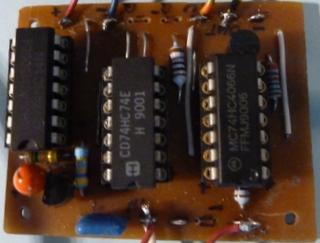
- DLO138-SPI-Display_SinusSquarewave.JPG (42.74 KiB) Viewed 1677 times
now the DLO-138 SPI TFT is nearly ready ( I have to integrate trigger_level for correct triggering).
But I have success with the DDS AD9850/1 with SPI.
Now I need only one extra line for FQ_UD (corresponds to CS ), DATA -> SPI-MOSi, AD_CLK -> SPI-CLK, AD_RST-> Ground.
Here some pictures from the test:
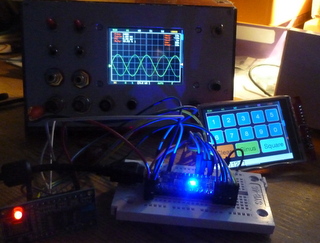
- DLO138sSPI_Display_test_AD9850_51_SPI.JPG (50.7 KiB) Viewed 1981 times
http://www.stm32duino.com/viewtopic.php?t=519
play an mp3 file from the sd card, add an fft for a dancing frequency display)
now I have modified the touch-input for DDS AD9851 to wobble the frequency between start-frequency and stop-frequency.
You can input the frequency-step-width in Hz and the time /step in ms.
The video on youtube:
I haven’t been able to work on this…
Before that, I had only an analog oscilloscope in my life. I have a few questions. What is timebase? How to calculate the signal frequency? What is xzoom?
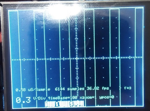
- IMG_20170410_160223.jpg (145.03 KiB) Viewed 1838 times
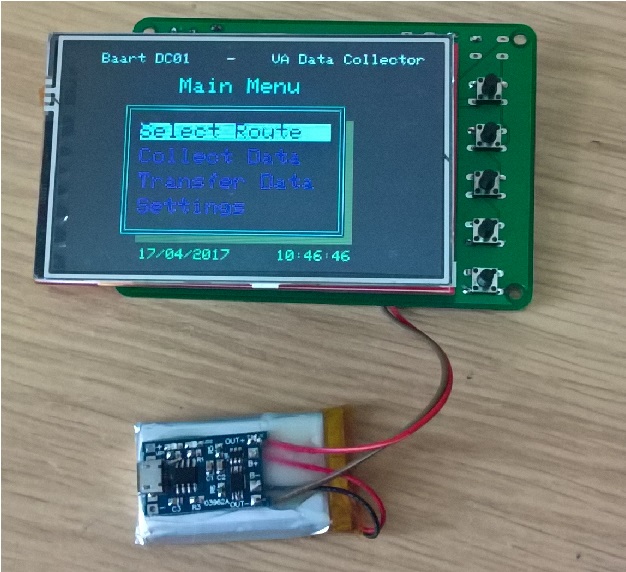
- WP_20170417_10_46_28_Pro.jpg (184.87 KiB) Viewed 1756 times
The V2 board will have a charging facility for LiPo batteries from the USB. Ive also thought to put a link in to connect the CS to either the EEPROM or the SD card on the TFT shield – all usable pins were used so I cant have a CS for both.
Once I have it made and I know I havent made a booboo, I’ll put the eagle files on github.
I’m also thinking about selling a few on eBay ready assembled with EEPROM fitted and the bootloader burned into the blue pill. The cost will be about £25 GBP, maybe less depending on if I can get the parts cheaper in bulk.
Steve
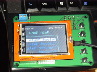
.. also placing the bluepill on the same side of the board as the display… you are right.. it was not a good move.
Other than those two issues.. its working fine. ![]()
Today I did some fancy thing I was planning for some time. Replaced chip on one of my “BluePill” boards with STM32F303 microcontroller.
Sure I am not the first one doing that, I know. Many have thoughts that would be nice if chinese manufacturers would make cheap “F303 Pills”, but there are none (AFAIK). So, we can make one, pinouts are the same as F103. Here my pictures:
http://bildites.lv/a/pjuhvaf5#6jv5nwen
One of pics shows this board running tomeko.net “MiniScope v2d” firmware.
I thought, maybe that is something to consider here in our “O-Scope” variations. If someone write code for F303 (better ADCs, etc), with such BluePill conversion we have “drop-in, pin-compatible” hardware.
Technically, I did “blow off” old chip with hot air pistol, and soldered STM32F303CBT6 in place.
Thoughts, anyone?
Steve
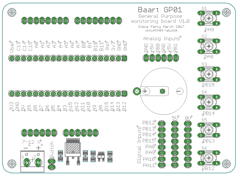
- GP01 pins.jpg (164.99 KiB) Viewed 2125 times
… Looks around for a moderator control panel and the delete post button …
… Looks around for a moderator control panel and the delete post button …
http://hackaday.com/2017/06/15/hackaday … he-masses/
https://hackaday.io/project/20821-multiscope
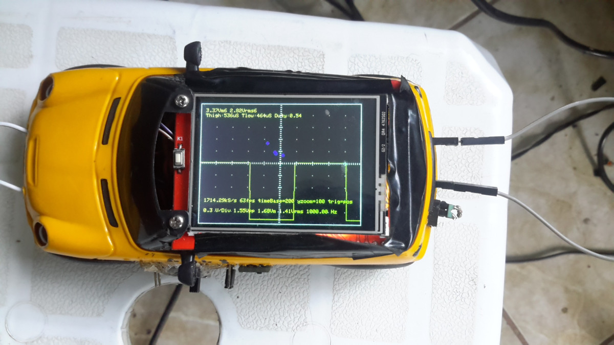
http://hackaday.com/2017/06/15/hackaday … he-masses/
https://hackaday.io/project/20821-multiscope
Congratulation!
Edit: (if the credits are present on the hackaday post…)
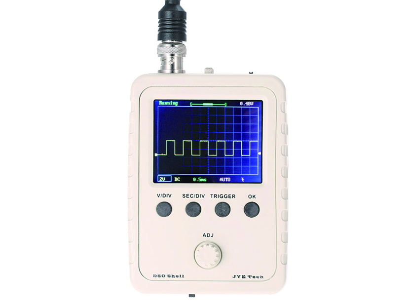
https://www.seeedstudio.com/DSO-Shell-D … -2929.html
Yet another STM32F103 based DSO (probably a clone)
He has some other good repair and test videos.
[rexnanet – Wed Aug 30, 2017 12:45 pm] –
Is there support for F303’duino?
Use STMs Core or STM32GENERIC
[RogerClark – Wed Aug 30, 2017 9:12 pm] –[rexnanet – Wed Aug 30, 2017 12:45 pm] –
Is there support for F303’duino?Use STMs Core or STM32GENERIC
Thanks!
I’ll give it a try when I solder the F303 on the BluePill board.
[rexnanet – Thu Aug 31, 2017 1:44 pm] –[RogerClark – Wed Aug 30, 2017 9:12 pm] –[rexnanet – Wed Aug 30, 2017 12:45 pm] –
Is there support for F303’duino?Use STMs Core or STM32GENERIC
Thanks!
I’ll give it a try when I solder the F303 on the BluePill board.
My best wishes for such experiments. I have two BluePils “modded” with F303, one with separated digital and analog power pins, one left as it was, connected. Both free right now for tests of anything interesting.
Do you have a video of the F303 oscilloscope version from that forum (“Murzik”)?
[rexnanet – Thu Aug 31, 2017 4:41 pm] –
Thanks ThunderOwl!Do you have a video of the F303 oscilloscope version from that forum (“Murzik”)?
I don’t have a video of it right now, but I can make a video or some screenshots with certain frequencies displayed some next days.
Here are screens of my weird construction, but there are no pics that would show performance:
http://bildites.lv/a/sfkqpxdx#tjbrytfu
[ThunderOwl – Thu Aug 31, 2017 8:21 pm] –
I don’t have a video of it right now, but I can make a video or some screenshots with certain frequencies displayed some next days.
Here are screens of my weird construction, but there are no pics that would show performance:
http://bildites.lv/a/sfkqpxdx#tjbrytfu
A video of it working would be great! It’s better to see the update rate and the overall graphical look and UI responsiveness.
From the photos it looks good. You went with a LQFP adapter instead of the BluePill board, why was that? Not to waste a board?
The TFT case looks great. It includes that 5V booster and the Battery from the other photos, right?
What is that 8 pin DIP chip? An input op-amp? Or is it that AC/DC switch?
Adapter board – I think I had it previous of any chinese boards that I acquired later.
Maybe we should migrate this talk to the other post…
void fetch() {

int channel = PIN_MAP[analogInPin].adc_channel;

adc_set_sample_rate(ADC1, ADC_SMPR_1_5);

adc_set_sample_rate(ADC2, ADC_SMPR_1_5);

adc_set_reg_seqlen(ADC1, 1);

adc_set_reg_seqlen(ADC2, 1);

ADC1->regs->SQR3 = channel;

ADC2->regs->SQR3 = channel;
ADC1->regs->CR1 |= 0x70000; // ADC_CR1_FASTINT;

ADC1->regs->CR2 |= ADC_CR2_CONT | ADC_CR2_SWSTART;

ADC2->regs->CR2 |= ADC_CR2_CONT | ADC_CR2_SWSTART;

ADC2->regs->CR1 |= 0x70000; // ADC_CR1_FASTINT;

nvic_globalirq_disable();

for (int j = 0; j < maxSamples ; j+=2 )

{

while (!(ADC1->regs->SR & ADC_SR_EOC))

;

dataPoints[j] = ADC1->regs->DR & ADC_DR_DATA;

while (!(ADC2->regs->SR & ADC_SR_EOC))

;

dataPoints[j+1] = ADC2->regs->DR & ADC_DR_DATA;

}

nvic_globalirq_enable();

}
like
void setADCs ()

{

int pinMapADCinA = PIN_MAP[analogInPinA].adc_channel;

int pinMapADCinB = PIN_MAP[analogInPinB].adc_channel;

adc_set_sample_rate(ADC1, ADC_SMPR_1_5); //7_5 13_5

adc_set_sample_rate(ADC2, ADC_SMPR_1_5);
// adc_reg_map *regs = dev->regs;
adc_set_reg_seqlen(ADC1, 1);
ADC1->regs->SQR3 = pinMapADCinA;
ADC1->regs->CR2 |= ADC_CR2_CONT; // | ADC_CR2_DMA; // Set continuous mode and DMA
ADC1->regs->CR1 |= ADC_CR1_FASTINT; // Interleaved mode
ADC1->regs->CR2 |= ADC_CR2_SWSTART;
adc_set_reg_seqlen(ADC2, 1);
ADC2->regs->SQR3 = pinMapADCinB;
ADC2->regs->CR2 |= ADC_CR2_CONT; // ADC 2 continuos
ADC1->regs->CR1 |= ADC_CR1_FASTINT; // Interleaved mode
ADC1->regs->CR2 |= ADC_CR2_SWSTART;
}
But channel 2 will not be sampled at the same time as channel 1. It will be offset by 7 ADC clocks.
If setting ADC2 to pinB works, than the what I said before should be valid.
EDIT: read http://www.st.com/content/ccc/resource/ … 258017.pdf
[ThunderOwl – Thu Mar 09, 2017 9:59 am] –
Proud me, i am featuret at tomeko.net (bottom of “v2d” page) :
Made my “first” attempt at replicating your feats!
Is it a simple case of desoldering the F103 and soldering the F303? Nothing else?
How did you test you swap?
I’m asking because I’ve swapped them successfully, then opened a “blinky” example on keil uVision 5 and after some trial and error, got the programmer to detect the board by switching one of the jumpers to “1” (the one next to the reset button) and after a few seconds of no led blinking, “magic smoke” begins to appear! ![]() I saw the led blinking once but after switching the board off, it no longer worked and magic smoke keeps appearing if I power it up (using the ST-link programmer).
I saw the led blinking once but after switching the board off, it no longer worked and magic smoke keeps appearing if I power it up (using the ST-link programmer).
[Squonk42 – Sun Sep 30, 2018 9:43 am] –
Sorry about my stupid question: I don’t see any anti-aliasing filter on the ADC input, is this function performed by the 1 Mohm resistor and some stray capacitance?
Pretty much, yes. The integrity of the signal is not something we have actually analysed in any detail. It would be possible to add some input protection and filtering, however given that there are other problems with the design (the common ADC and signal ground for example), the absolute fideleity of what appears on the display is somewhat of an unknown.
Good enough for government work though ![]()
[ahull – Sun Sep 30, 2018 7:38 pm] –
…
Good enough for government work though
+1
…. from a previous 2x “gov. worker.”
Ray
But all signals in the frequency band between sampling frequency and half of it will fall back at full amplitude into the low frequency band. SPI would be a good candidate.
I was just thinking of the best (laziest) way to qualify our BluePill F4 board analog design (ferrite bead vs. analog LDO, 2 vs. 4-layer PCB…) and compare it to the other STM32-based boards: “original” BluePill, Baite Mapple Mini, ST Nucleo F103.
For this, I would need to capture at the highest possible sampling rate and perform an FFT (possibly not onboard) to measure SNR, noise floor, PSRR-dc, PSRR-ac and PMSR. Starting from the Pig-O-Scope was one of my options, but I will need an anti-aliasing filter to get any meaningful result.
To be checked on black and mini F4 boards.
[Squonk42 – Sun Sep 30, 2018 9:43 pm] –
For this, I would need to capture at the highest possible sampling rate and perform an FFT (possibly not onboard) to measure SNR, noise floor, PSRR-dc, PSRR-ac and PMSR. Starting from the Pig-O-Scope was one of my options, but I will need an anti-aliasing filter to get any meaningful result.
Wouldn’t noise floor, PSRR-dc, and PSRR-ac be measured with the input grounded? For those cases there’s nothing from the input signal to alias and I would expect internally generated spurious interference, e.g. SPI, to mostly be introduced after any anti-alias filter.
For SNR you wouldn’t strictly need an anti-aliasing filter if the source tone is free from harmonics (this may be problematic) and the frequency is selected such that any distortion harmonics do not alias on top of one another. The usual concern here is spur free dynamic range.
I’m not clear on what PMSR might be.
Ray
[MarkB – Mon Oct 01, 2018 1:55 pm] –[Squonk42 – Sun Sep 30, 2018 9:43 pm] –
For this, I would need to capture at the highest possible sampling rate and perform an FFT (possibly not onboard) to measure SNR, noise floor, PSRR-dc, PSRR-ac and PMSR. Starting from the Pig-O-Scope was one of my options, but I will need an anti-aliasing filter to get any meaningful result.Wouldn’t noise floor, PSRR-dc, and PSRR-ac be measured with the input grounded? For those cases there’s nothing from the input signal to alias and I would expect internally generated spurious interference, e.g. SPI, to mostly be introduced after any anti-alias filter.
For SNR you wouldn’t strictly need an anti-aliasing filter if the source tone is free from harmonics (this may be problematic) and the frequency is selected such that any distortion harmonics do not alias on top of one another. The usual concern here is spur free dynamic range.
I’m not clear on what PMSR might be.
Yes, you are right for PSRR-dc and PSRR-ac, but for testing PSMR (Power Supply Modulation Ratio, sorry for the typo), you need to drive the ADC input and add perturbation to the power supply at the same time, see http://www.analog.com/en/technical-arti … d-adc.html.
For the SNR, my plan was to use a pure sine wave at half the sampling frequency) as the worst case and to test both with/without SPI.
[mrburnette – Mon Oct 01, 2018 2:04 pm] –
The “cheap clones” have a 2-sided PC board, no separate analog and separate digital ground planes. The original Maple design was a 4-layered board. The noise floor for analog signals is now influenced by the internal dynamics of the digital logic as well as external PC board capacitive and inductive coupling.Ray
Unfortunately, I don’t have an original Maple board, only a Baite clone which is indeed different. I accept donations for science ![]()
However, the problem is not necessarily 2-layer vs. 4-layer or separate ground planes, but ground return path and common power supply for analog/digital combined with poor STM32 ADC PSRR performance (I have seen figures as low as 20 dB, but can’t get my hands on it right now).
Of course, we could go 4-layer with separate analog LDO just to be safe, but 1) this will add $1 to the bill for a <$10 board, 2) I have seen many other MCUs working fine with only 2-layer and no separate LDO, and 3) even ST is recommending only a ferrite bead and implemented it as such on their Nucleo F103 board with only 2-layer PCB.
This is why we want to verify what is really making a difference here.
[Squonk42 – Mon Oct 01, 2018 2:18 pm] –
For the SNR, my plan was to use a pure sine wave at half the sampling frequency) as the worst case and to test both with/without SPI.
Right, what I was suggesting is using something slightly less than half the sampling frequency so distortion harmonics don’t land on top of each other after the FFT.
For example with 0.45*Fs, the second harmonic would show up at 0.9*Fs (aliased to 0.1*Fs), the third harmonic at 1.35*Fs (aliased to 0.35*Fs), and so forth.
[MarkB – Mon Oct 01, 2018 3:05 pm] –[Squonk42 – Mon Oct 01, 2018 2:18 pm] –
For the SNR, my plan was to use a pure sine wave at half the sampling frequency) as the worst case and to test both with/without SPI.Right, what I was suggesting is using something slightly less than half the sampling frequency so distortion harmonics don’t land on top of each other after the FFT.
For example with 0.45*Fs, the second harmonic would show up at 0.9*Fs (aliased to 0.1*Fs), the third harmonic at 1.35*Fs (aliased to 0.35*Fs), and so forth.
Yes, very good idea, thank you!