here I have build a little synthesizer with an Attiny85:
https://github.com/ChrisMicro/AttinySound
Now I got a STM32F103 BluePill from a friend and I think it could be fun to build the synth with this board.
I don’t want to use an external DAC and the goal is to create the sound only with a digital output pin.
In the Attiny85 synth this is done with a PWM-ISR and the results are quite amazing for this little chip.
Here I started the repository for the BluePill synthesizer:
https://github.com/ChrisMicro/BluePillSound
Unfortunately I didnt’ find a routine which can drive the PWM for sound generation.
Therefore I used to start hard coded sigma delta DAC. I ported the Talkie library which makes the synth speak with human like voice as an example ( Yes the BluePill can speak now ).
Do you have any hint where I can find a PWM-DAC ( probably with DMA )?
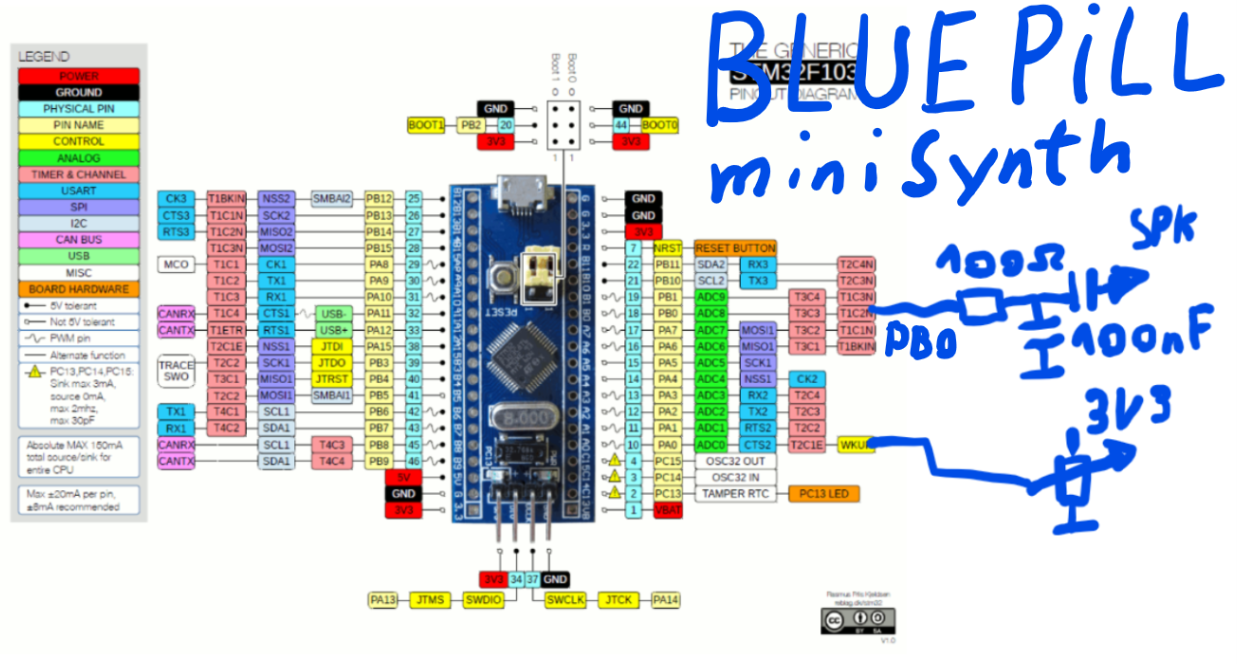
The speaker is connected to PB0.
google search
“site:stm32duino.com HardwareTimer”
Doesn’t the tone lib produce only square wave sounds?
Here I made an example with two wav-samples: a girls singing voice and a piano:
https://github.com/ChrisMicro/BluePillS … taPinSound
The sound output is PB12. You can directly connect a audio amplifier to it. The sound is a little bit better, if you put a 100Ohm/100nF low pass between.
The whole thing sounds a little bit like Mickey Mouse in concert with a more or less gifted piano player ![]()
I saw that in this forum there are more people using some sound generation. e.g.
http://www.stm32duino.com/viewtopic.php?f=19&t=1198
But they use a hardware DAC which is in my humble opinion not necessary if there is the right software driver.
The people can use my sigma delta principle, but it is a blocking routine and it needs a sample buffer which can be memory consuming.
I know there is the analogWrite function but it seems not to work on PB12 which is at the moment my sound output.
Here in the forum someone tried to speed up the PWM write:
http://www.stm32duino.com/viewtopic.php?t=587
Ah, yes. Reading helps.
Just for test I tried this which gives a ~33kHz PWM.
// PWM rate 1.1khz

int led = PB0;
HardwareTimer pwmtimer(3);
void setup()
{
pwmtimer.setPeriod(30);
pinMode(led, PWM);
pwmWritefast(led, 500);
}
void loop()
{
for (int a =0; a<2000;a++)
{
pwmWritefast(led,a);
delayMicroseconds(100);
}
}
void pwmWritefast(uint8 pin, uint16 duty_cycle)
{
timer_set_compare(PIN_MAP[pin].timer_device, PIN_MAP[pin].timer_channel, duty_cycle);
}
Hmm … well … I didn’t want to invest to much time in the whole thing because I just got one of this boards from a friend and I thought I can do a quick hack … but now I spend to much hours …
Did you see, I used your code for the fast pin access:
https://github.com/ChrisMicro/BluePillS … GPIOPort.h
Do you want to have any special copyright text?
https://github.com/ChrisMicro/BluePillS … GPIOPort.h
Do you want to have any special copyright text?
Yes you can use PWM output to generate a wave. I did a dirty port of the TMRPCM library that works ok so far and does that.
You can use interrupts to reload the timers registers, and you can use DMA.
My library is in github in an old version with a few bugs. There is a tread about a ZX tape player where I was helping Buleste use it, and posted some of the bugs I found, but haven’t uploaded the corrections to github yet.
Further I worked on using DMA rather than interrupts to reload the timer compare registers, and that reduced CPU usage quite a bit. That is not uploaded anywhere yet. I got it working a couple of weeks ago and haven’t had much time yet to clean up and upload.
Once I clean it up and upload it I will post in the libraries section. You can take the parts that set the timer registers and play the samples and use it for anything else other than wav files.
Helo Viktor,
that sounds very interesting. When do you think the library is online?
Here is an application note from ST which could be probably very useful:
http://www.st.com/en/embedded-software/ … dithr.html
Meanwhile I will add more samples with the software sigma delta DAC.
Helo Viktor,
that sounds very interesting. When do you think the library is online?
Here is an application note from ST which could be probably very useful:
http://www.st.com/en/embedded-software/ … dithr.html
Meanwhile I will add more samples with the software sigma delta DAC.
Thank you very much for posting the code. I would have a first little question:
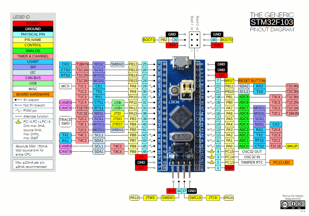
Which Pins on the STM32F103 can be used for sound output? I assume that we can’t use PB12 because there is no connection to the timer units.
Would it make sense to say that PB0 is used in general for sound output? And for later uses: Is it possible to have a stereo PWM? Let’s say the second channel on PB1?

	extern byte speakerPin = 0;

extern byte speakerPin2 = 0;

extern uint8_t CSPin = 0;

extern uint16 resolution = 0;

extern uint8 repetition = 0;

extern byte lastSpeakPin = 0;
	extern byte speakerPin = 0;

extern byte speakerPin2 = 0;

extern uint8_t CSPin = 0;

extern uint16 resolution = 0;

extern uint8 repetition = 0;

extern byte lastSpeakPin = 0;
So this would mean
T4C1 ==> PB6
T4C2 ==> PB7
on the BluePill STM32F130 in the picture above. Right?
So this would mean
T4C1 ==> PB6
T4C2 ==> PB7
on the BluePill STM32F130 in the picture above. Right?
https://github.com/ChrisMicro/BluePillSound
^^^wow, this is *excellent*, effectively it is a ‘1 bit’ delta-sigma DAC with just gpio bit banging and a simple RC lowpass filter !
http://www.beis.de/Elektronik/DeltaSigm … Sigma.html
similar concept:
https://www.allaboutcircuits.com/techni … nto-a-dac/
it’s not hard to imagine that 1 could program the usb-audio side interfacing wav bytes received from a PC, etc, convert that to delta-sigma over sample at 64x assuming 10khz being acceptable upper limit, pump out the bitstream at 640,000 bits per second over 2 gpio pins (L/R channels)
& 1’d have a STM32F103 USB HD-audio! ![]()
but i’d guess we’d have a very busy STM32F103 doing all that delta-sigma conversions ![]()
not sure what is that ‘upper limit’ of a stm32103 throughput with this
if we try to do 48k samp per sec x 16x oversample sigma-delta, that’d be perhaps be pumping the gpio at 768k bits per sec?
seemed quite feasible still ![]()
and we can make the stm32f103 busier sampling a mic at 1 M samp per sec (u can track a flying bat!), or perhaps even more ambitious drive 3ch, 5ch or 7ch? ![]()
Thanks ![]() Did your try it on your microcontroller and have you listened to the sound?
Did your try it on your microcontroller and have you listened to the sound?
Meanwhile I made an experiment using the DMA to shift out the sigma delta bits:
https://github.com/ChrisMicro/BluePillS … SigmaDelta
It produces a sine wave just to check if the principle is working.
The explanations for the sigma delta principle is always explained a little bit complicated.
But there is one main rule:
– the higher the frequency the better the DAC resolution
( The sigma delta principle distributes the quantization noise over the entire frequency band. Therefore as broader the frequency band as less the noise )
if you look in the code you can see that the code for the sigma delta DAC is very, very simple:
    // sigma delta DAC

for (n = 0; n < NumberOfCyclesYouWantToUseForOneSample; n++)

{

integrator += dacOutpuValue - oldValue;

if (integrator > 0)

{

oldValue = DACRESOLUTION; // DACRESOLUTION=255 for 8Bit

fastWrite(FASTSOUNDPIN, 1);

}

else

{

oldValue = 0;

fastWrite(FASTSOUNDPIN, 0);

}

}
Usually I compile the code on the Arduino IDE 1.6.6 with the Board Option “generic STM32F103 series” selected.
On Hackaday I found a installation procedure http://hackaday.com/2017/03/30/the-2-32 … debugging/
Than I have a board option “BluePill” but for some reason I don’t have the “HardwareTimer” class.
What is the correct way to have it on the BluePill?
And how should the code look like calling a periodic interrupt with the “HardwareTimer” class.
I have the tendency now to start “bare metal” programming of the timer like I did it for the DMA to skip all this confusing dependencies.
There was a mp3 player for the ESP8266 that did that, but I need to know how those sigma Delta DACs work before I can make full sense of the code.
That’s a very interesting hint. Using the SPI would realy speed up the time needed to write the DAC buffer.
I’m wondering how much CPU time it would take to output at 48Khz with at least 8 bit resolution.
I have made a new version where I write uint32 to the DMA buffer which speeds up the timing. Now it needs ~10us do write the DMA buffer which could theoretical lead to a sampling frequency of 100kHz.
The resolution of the DAC is hard to estimate, because it is dithering the noise over multiple samples.
Now I used also the “HardwareTimer” to generate the sine wave in a interrupt handler loop:
I’m wondering how much CPU time it would take to output at 48Khz with at least 8 bit resolution.
Why do you simply flash my DMA-GPIO sigma delta example and measure it with an oscilloscope?
http://www.stm32duino.com/viewtopic.php?f=19&t=107
is all i’ve or can make, probably can’t measure up to those hi-fi mhz traces
nevertheless would check out the synth
That would give 36Mbit in a single pin.
The SPI port can do 36Mbit in a single pin too, but with 16bit transfers it only needs to read from ram 1 per 16 bits. So the DMA controller is able to maintain the SPI 1 word buffer full all the time.
Now if you wanted to use multiple pins with the SPI you could use both SPI, but with the GPIO ports I guess up to 16 channels if they are all in the same GPIO port, you are not adding any extra DMA transfer, would be interesting to push it to the limit…
Anyway, about using the SPI, you can set the DMA transfer pretty much similar to how you set it for GPIO, but need to enable the SPI port DMA request flag. Check the SPI library where we added dmaSend functions to do DMA transfers to get ideas.
You could also set the port to a different speed, since the speed is known, you can refill the buffer at the required rate, and keep the DMA in circular mode as you do for the GPIO.
I just realized that there is an upcoming Arduino sound library:
https://www.arduino.cc/en/Reference/ArduinoSound
Because you wrote the SD card audio player it could be a good idea to make the API somehow compatible.
I just realized that there is an upcoming Arduino sound library:
https://www.arduino.cc/en/Reference/ArduinoSound
Because you wrote the SD card audio player it could be a good idea to make the API somehow compatible.
I think it is this one:
https://github.com/arduino-libraries/Ar … master/src
and also very important, the I2S-class:
https://github.com/arduino/ArduinoCore- … rc/I2S.cpp
I think it is this one:
https://github.com/arduino-libraries/Ar … master/src
and also very important, the I2S-class:
https://github.com/arduino/ArduinoCore- … rc/I2S.cpp
The only board with I2S codec I have is a STM32F4 discovery.
I think for quick an cheap solutions the I2S DAC can be replaced by any other audio output device like
– built in PWM
– the DMA sigma delta
– SD-Card ( to store sounds )
As audio input
– a mircrophone
– a build in ADC
– built in synthesizer routines
– or stored sounds on a SD-card
could serve.
The sound library is made for attaching different in- and output devices but the only low level driver directly usable with it is for the Arduino Zero witch a SAMD21 microcontroller.
Because I think in general solutions usable for all people it would be useful if for any board supports a driver compatible to the Arduino sound library. Probably the best people suitable for this tasks are the core developers.
viewtopic.php?f=19&t=533
I never finished the project 100% (maybe 95%) because I lost interest & totally busy with my 2 kids
In short:
The best idea is to buy some cheap PT8211 DAC’s to get a “true” 16-bit sound. (they are in the (Euro) Cent region, so buy 20 or 50 for a few bugs)
There are two things you can do:
1. Using a STM32F103xx without I2s – I pretty shure (as I can remember) to get the DAC with only SPI to work. I think Victor did this.
2. Using a cheap STM32F103 board with activated I2s, like this one:
https://www.aliexpress.com/item/STM32F1 … 62693.html
I was using the board above to get a wavetable synth with 4 voice polyphony AND 4 individual outputs! (2 DAC – stereo = 4 mono) AND using the third SPI for everything else (like SD-Card, Flash RAM, Display)
The I2S-wavetable routine was totally slim and DMA driven (thanks to Victor) without MCU wasting (you have to read my complete thread to get the code, because I can’t remember everything)
The next advantage over the board above (I thing the xxxVET board is even much better): 256kb Flash and 48 RAM. So more RAM more accurate wavetables.
Also search this forum for: USB MIDI HID. I managed to get the STM32 via USB recognized as MIDI device. So no external MIDI hardware neccessary (if not needed).
A next level of synth MCU programming would be the STM32F4, because of it’s floting point features, so no stupid oldschool wavetables, but realtime processing sounds.
Edit: There must be another (at least one) thread about the PT8211 in this forum, can be easily found with the search function.
Edit 2: Found the SPI version of the PT8211 DAC, originally written by Vassilis (not Victor, sorry for that): viewtopic.php?f=18&t=519
Edit 3: I see, ChrisMicro, that you found already the thread ![]()
http://www.beis.de/Elektronik/DeltaSigm … Sigma.html
i’t guess it is possible to imagine that given stm32f103 is a full usb device, it may be possible to create usb-audio on the usb side and for those digital audio, bit bang that on the pin, do that RC filter, some simple amplifiers (e.g. some transistors) and a 3.5mm jack and perhaps you may achieve a 24 bit stereo USB HD audio
i think it isn’t really very different from PWM DAC
did a little ‘crazy’ computations, assuming that we have single channel audio at 48 ksps, and lets say we want a 24 bit gratuity, so that means 2^24 ~ 16,777,216 ‘levels’ so that means a sample rate of 16.77 million bits / s x 48,000 ~ 805,306,368,000 ~ 805.3 gigabits per second? ![]()
hmm, strange, but even if you do super max overclock for stm32f103 u may ‘never’ get there 805 gigahertz not even intel i7 with the most powerful processor gets there ![]()
I would like to generate some short sound effects with the blue pill.
Or any alternative way to do it?


