I have been “playing” with building a VFD for my CNC machine. I would image one would ask… why for the love of god would you want to build one of these things when they sell for peanuts online nowadays. and the answer is.. I got my hands on a very fancy spindle that requires frequencies of up to 1000Hz and the cheap drives i can see online seem to stop at about 3-400Hz. Also i kind of like to use this to learn and share.
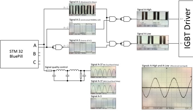
the main part that i am currently concerned with is the 3 phase sine wave generator. Here is what i have done so far:
I have in principal made it work by using simple logic and “naive” code.
here is the code:
PROGMEM const uint16_t Half_Sine[] = {

0,  4,  8, 13, 17, 22, 26, 31, 35, 40, 44, 48, 53, 57, 61, 66, 70, 74, 79, 83, 87, 91, 95,100,104,108,112,116,120,124,

128,131,135,139,143,146,150,154,157,161,164,167,171,174,177,181,184,187,190,193,196,198,201,204,207,209,212,214,217,219,

221,223,226,228,230,232,233,235,237,238,240,242,243,244,246,247,248,249,250,251,252,252,253,254,254,255,255,255,255,255,

256,255,255,255,255,255,254,254,253,252,252,251,250,249,248,247,246,244,243,242,240,238,237,235,233,232,230,228,226,223,

221,219,217,214,212,209,207,204,201,198,196,193,190,187,184,181,177,174,171,167,164,161,157,154,150,146,143,139,135,131,

128,124,120,116,112,108,104,100, 95, 91, 87, 83, 79, 74, 70, 66, 61, 57, 53, 48, 44, 40, 35, 31, 26, 22, 17, 13,  8,  4

};
int PhaseA_OUT = PA8; // TIM1_CH1 pwm output for phase A sine wave
int PhaseA_High_EN = PB10;
int PhaseA_Low_EN = PB11;
int PhaseA_EN_State = 0;
int PhaseB_OUT = PA9; // TIM1_CH2 pwm output for phase B sine wave
int PhaseB_High_EN = PB8;
int PhaseB_Low_EN = PB9;
int PhaseB_EN_State = 0;
int PhaseC_OUT = PA10; // TIM1_CH3 pwm output for phase C sine wave
int PhaseC_High_EN = PB5;
int PhaseC_Low_EN = PB6;
int PhaseC_EN_State = 0;
int Amplitude_OUT = PA6; // TIM3_CH1 pwm channel for controlling the amplitude of the sinewave by using the sine wave channels as carriers for higher frequency pwm
int Amplitude_CTRL = 100; // variable that controls the duty cycle of Amplitude_OUT pin
int Frequency_CTRL = 100; // variable that controls the frequency of the sine wave
int Array_Limit = 179;
int a = 0;
int b = 0;
int c = 0;
int i = 0; // Array Increment
int Dead_Band_Delay = 10;
HardwareTimer CarrierTimer(1);
HardwareTimer AmplitudeTimer(3);
void setup() {
CarrierTimer.setPrescaleFactor(1);
CarrierTimer.setOverflow(256);
AmplitudeTimer.setPrescaleFactor(8);
AmplitudeTimer.setOverflow(500);
pinMode(PhaseA_OUT, PWM);
pinMode(PhaseA_High_EN, OUTPUT);
pinMode(PhaseA_Low_EN, OUTPUT);
pinMode(PhaseB_OUT, PWM);
pinMode(PhaseB_High_EN, OUTPUT);
pinMode(PhaseB_Low_EN, OUTPUT);
pinMode(PhaseC_OUT, PWM);
pinMode(PhaseC_High_EN, OUTPUT);
pinMode(PhaseC_Low_EN, OUTPUT);
pinMode(Amplitude_OUT, PWM);
digitalWrite(PhaseA_High_EN, HIGH);
digitalWrite(PhaseA_Low_EN, LOW);
}
void loop() {
pwmWrite(Amplitude_OUT, Amplitude_CTRL);
if (a < 60) {
b = a + 120;
} else {
b = a - 60;
}
if (a < 120) {
c = a + 60;
} else {
c = a - 120;
}
a++;
if (a > Array_Limit) {
a = 0;
digitalWrite(PhaseA_High_EN, (PhaseA_EN_State) ? HIGH : LOW);
digitalWrite(PhaseA_Low_EN, (PhaseA_EN_State) ? LOW : HIGH);
PhaseA_EN_State = ! PhaseA_EN_State;
}
if (b == 0) {
digitalWrite(PhaseB_High_EN, (PhaseB_EN_State) ? HIGH : LOW);
digitalWrite(PhaseB_Low_EN, (PhaseB_EN_State) ? LOW : HIGH);
PhaseB_EN_State = ! PhaseB_EN_State;
}
if (c == 0) {
digitalWrite(PhaseC_High_EN, (PhaseC_EN_State) ? HIGH : LOW);
digitalWrite(PhaseC_Low_EN, (PhaseC_EN_State) ? LOW : HIGH);
PhaseC_EN_State = ! PhaseC_EN_State;
}
pwmWrite(PhaseC_OUT, Half_Sine[c]);
pwmWrite(PhaseA_OUT, Half_Sine[a]);
pwmWrite(PhaseB_OUT, Half_Sine[b]);
delay_us(Frequency_CTRL);
}
[bogdanaioane – Wed Jan 16, 2019 5:04 pm] –
… I got my hands on a very fancy spindle that requires frequencies of up to 1000Hz and the cheap drives i can see online seem to stop at about 3-400Hz. Also i kind of like to use this to learn and share….
Do you guys think i could get some help in implementing a similar solution for the F103? The way i imagine this is that the STM32 board would do nothing other than the PWM sine generation with a frequency determined by some kind of external signal or communicated via serial by another MCU.
http://stm32duino.com/viewtopic.php?t=2351
“ted” built a single phase sine wave generator that goes up to 15KHz with external filtering, but multi-phase is much more complex and may require an approach such as Magic Sine Waves. https://www.tinaja.com/glib/msinprop.pdf
Other approaches in general can be found on Google: https://www.google.com/search?q=uC+code … sine+waves
Ray
I am trying to put pictures of the progress I’m making but I get an “image too large” error. surely an image under 100kb is not a large image these days. Am I doing something wrong?
[bogdanaioane – Wed Jan 16, 2019 7:24 pm] –
Thanks Ray, Ill have a read through these.
I am trying to put pictures of the progress I’m making but I get an “image too large” error. surely an image under 100kb is not a large image these days. Am I doing something wrong?
Use some picture posting site. I use imgur.com.
[edit] I see you were using a picture site, Make sure you use their suggested embed code. See what I did in your first post to fix the image.[/edit[add 1 more timer
12.5kHZ, 90deg
HardwareTimer pwmtimer3(3);

HardwareTimer pwmtimer2(2);
void setup() {

pinMode(PA7, PWM);

pwmtimer3.pause();

pwmtimer3.setPrescaleFactor(1);

pwmtimer3.setOverflow(5760 - 1);

pwmtimer3.setCompare(TIMER_CH2, 2880);

pwmtimer3.refresh();

pwmtimer3.resume();

delay(50); // phase shift adjustment

pinMode(PA3, PWM);

pwmtimer2.pause();

pwmtimer2.setPrescaleFactor(1);

pwmtimer2.setOverflow(5760- 1);

pwmtimer2.setCompare(TIMER_CH4, 2880);

pwmtimer2.refresh();

pwmtimer2.resume();

}
void loop() {

}
reduce it below 50 kb
MTD6501C-HC1 3-Phase Brushless DC Sinusoidal Sensorless Fan Motor Driver
[ted – Thu Jan 17, 2019 7:14 pm] –
I think you need this, I am using them with no problems.
MTD6501C-HC1 3-Phase Brushless DC Sinusoidal Sensorless Fan Motor Driver
Thank you Ted, this looks very interesting.
Looking through the datasheet of the chip i can’t find a reference to the output frequency of the 3 phase signal. Or is it that what it does is it takes your input signal and phase shifts it into 3 separate signals 180deg apart which would mean that whatever freq you feed into the input, it would be the output freq as well.
[ted – Thu Jan 17, 2019 6:31 pm] –
For sine
https://www.stm32duino.com/viewtopic.ph … 0&start=30
I will read through this and try to make sense of it
thank you
[Rick Kimball – Wed Jan 16, 2019 7:25 pm] –[bogdanaioane – Wed Jan 16, 2019 7:24 pm] –
Thanks Ray, Ill have a read through these.
I am trying to put pictures of the progress I’m making but I get an “image too large” error. surely an image under 100kb is not a large image these days. Am I doing something wrong?Use some picture posting site. I use imgur.com.
[edit] I see you were using a picture site, Make sure you use their suggested embed code. See what I did in your first post to fix the image.[/edit[
That helps,
I will upload some pics of the work in progress. Is it useful/allowed to show circuit schematics or should i stick to the stm32 bit only?
 MTD6501C-HC1
You don’t need a generator it is inside the chip, so you connect the motor directly to it. The only one think you need to consider – how big is your motor = the current of the motor.
I will read the topic you linked in one of your previous replies as i think one of those is very close to what I am trying to accomplish
MTD6501C-HC1
produce 3 sine waves shifted 120 deg that what I sow on scope, 180 deg I think it is something else, you can’t have 3 phase shifted by 180 deg because the third one will be the same as the first.
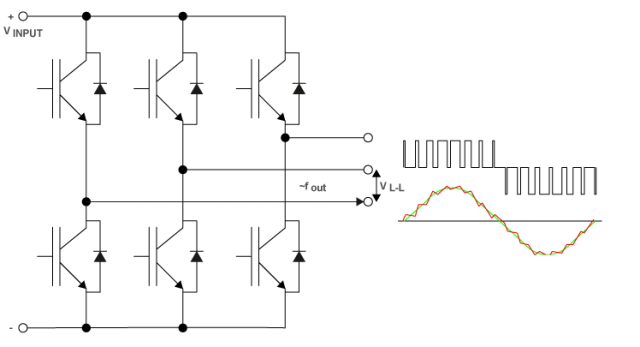
Thanks for the link for the inverter. This is pretty much what I’m trying to build but at a higher frequency. It would be great if i could find something like that that goes up to 1Khz.
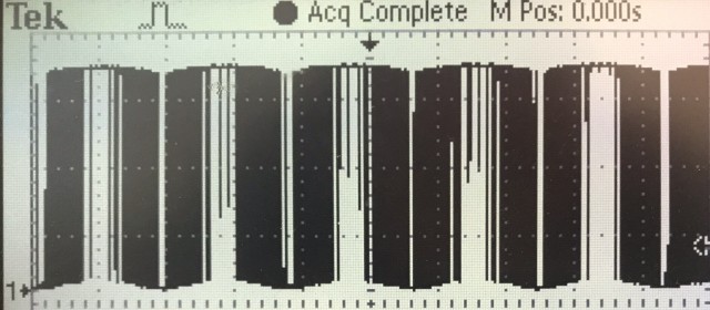
I will be playing with your sine generator this weekend. I have already tried it as is and get a full sinewave at about 7KHz but the 3 signals are not quite 120 deg out of phase but that I’m sure is fixable. The first thing i would like to do is see if instead of a full sinewave i can produce only half
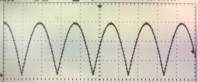
Something like this
and after filtering..
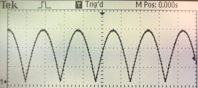
Then… i will have to toggle another pin at each “zero crossing” of the sine wave.
Something like this.
I will start working on it today and hopefully i can make some progress although I must admit I am a bit intimidated by the look of the code of your sine generator. (as i said at the beginning.. I’m not quite there yet) so any advice will be greatly appreciated.
viewtopic.php?t=3752
you need to create an algorithm for delay because it is depends to frequency.
[bogdanaioane – Sat Jan 19, 2019 10:00 am] –
Something like this.
actually with MAX 7410 you ok with any shape of the signals, just shifted 120 deg
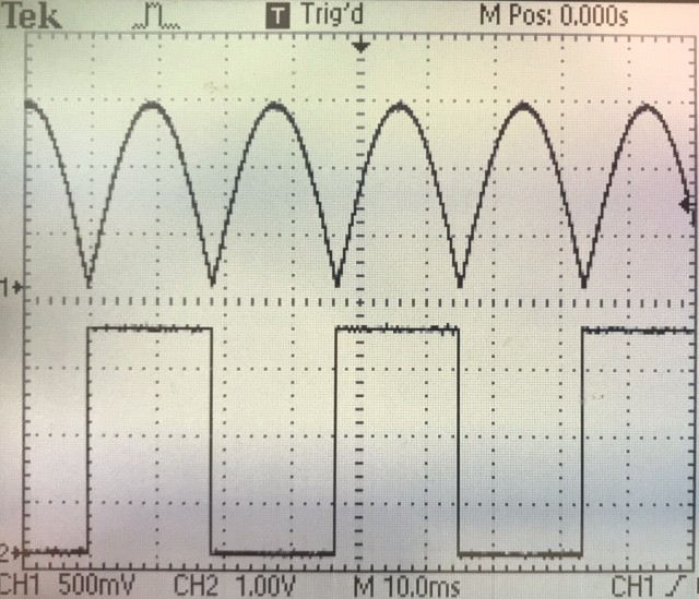
This is ultimately what I’m after:
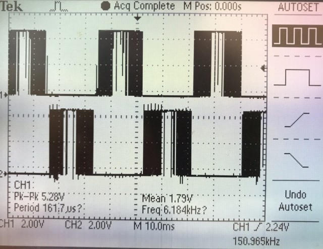
The two signals are essentially the positive and the negative halves of a sine wave. I obtained these by toggling an additional pin at teh beginning of every pass through the “half sine” array and passing that with the signal from one of the channels through some logic gates like i showed in my original post.
I am trying to understand the code in your sine application and have lots to read before I can make anything happen but it would be helpful if you could explain the config in your code below
  timer_dma_set_base_addr(dev1, TIMER_DMA_BASE_CCR2);

timer_dma_set_burst_len(dev1, 1);

timer_dma_enable_req(dev1, PIN_MAP[out1].timer_channel);

timer_set_reload(dev1, 102);

timer_set_prescaler(dev1, 0);
The code was assembled using existing programs and I didn’t go through details.
In my program lower frequency = higher quality of sine. For 7200 Hz you have 100 samples for 720 Hz 1000 samples for 360 Hz 2000 samples rate. For galvanic isolation use optocoupler, because it is hard to find a linear one, use the filter after isolation.
The SI5351 is a clock generator IC with 3 outputs, but it generates square waves.
However some simple analog filtering would produce a reasonably accurate since wave.
You would still need a microcontroller to setup and control the SI5351, but the major workload would be removed from the microcontroller
Ps SI5351 modules are available for less than $10 from places like AliExpress and even Adafruit sell them ( but not so cheaply )
If you don’t want to have to filter square waves from the SI5351 you could use 3 AD9850 modules, but they are much more expensive, and you would have to work out how to feel the master clock from one of the modules into the other 2 so that they are all in phase
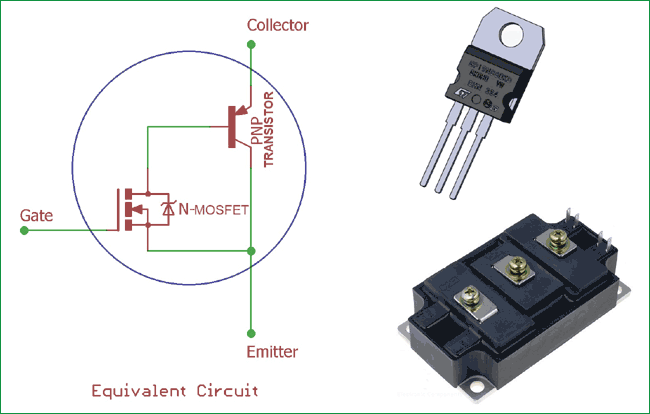
The issue with any sort of generator that eventually gives me an analog sinewave is that this signal essentially cannot be used for the purpose of driving IGBTs for high power motor applications, The signal needs to be a series of pulses the width of which is modulated into a sine wave that can be passed through an isolation barrier and into a driver for IGBTs or maybe MOSFETs such that, on the high voltage/power side, if we install a high voltage low pass filter we get a close to true sine wave. At these sort of voltages it is very important that the sine wave is as close to true as possible, otherwise there will be huge losses and motor issues. I have looked into some standalone chips like the ones you are suggesting but the problem remains that there is not much I can do with the signal they generate as i don’t know how (or even if its possible) to decompose the signal back into a PWM and Enable signals that i can use for the drivers of the FETS or IGBTs.
I have been working all day on this and managed to make some progress.
here is the code so far:
#include <Arduino.h>
PROGMEM const uint16_t Half_Sine_A[] = {
0 , 26, 53, 80, 107, 133, 160, 186, 212, 239, 265, 290, 316, 341, 366, 391, 416, 440, 464, 488,
512 , 535, 557, 579, 601, 623, 644, 665, 685, 704, 724, 742, 760, 778, 795, 812, 828, 843, 858, 873,
886 , 899, 912, 924, 935, 946, 955, 965, 973, 981, 989, 995, 1001, 1006, 1011, 1015, 1018, 1020, 1022, 1023,
1024, 1023, 1022, 1020, 1018, 1015, 1011, 1006, 1001, 995, 989, 981, 973, 965, 955, 946, 935, 924, 912, 899,
886 , 873, 858, 843, 828, 812, 795, 778, 760, 742, 724, 704, 685, 665, 644, 623, 601, 579, 557, 535,
512 , 488, 464, 440, 416, 391, 366, 341, 316, 290, 265, 239, 212, 186, 160, 133, 107, 80, 53, 26,
};
PROGMEM const uint16_t Half_Sine_B[] = {
886 , 899, 912, 924, 935, 946, 955, 965, 973, 981, 989, 995, 1001, 1006, 1011, 1015, 1018, 1020, 1022, 1023,
1024, 1023, 1022, 1020, 1018, 1015, 1011, 1006, 1001, 995, 989, 981, 973, 965, 955, 946, 935, 924, 912, 899,
886 , 873, 858, 843, 828, 812, 795, 778, 760, 742, 724, 704, 685, 665, 644, 623, 601, 579, 557, 535,
512 , 488, 464, 440, 416, 391, 366, 341, 316, 290, 265, 239, 212, 186, 160, 133, 107, 80, 53, 26,
0 , 26, 53, 80, 107, 133, 160, 186, 212, 239, 265, 290, 316, 341, 366, 391, 416, 440, 464, 488,
512 , 535, 557, 579, 601, 623, 644, 665, 685, 704, 724, 742, 760, 778, 795, 812, 828, 843, 858, 873,
886 , 899, 912, 924, 935, 946, 955, 965, 973, 981, 989, 995, 1001, 1006, 1011, 1015, 1018, 1020, 1022, 1023,
1024, 1023, 1022, 1020, 1018, 1015, 1011, 1006, 1001, 995, 989, 981, 973, 965, 955, 946, 935, 924, 912, 899,
886 , 873, 858, 843, 828, 812, 795, 778, 760, 742, 724, 704, 685, 665, 644, 623, 601, 579, 557, 535,
512 , 488, 464, 440, 416, 391, 366, 341, 316, 290, 265, 239, 212, 186, 160, 133, 107, 80, 53, 26,
0 , 26, 53, 80, 107, 133, 160, 186, 212, 239, 265, 290, 316, 341, 366, 391, 416, 440, 464, 488,
512 , 535, 557, 579, 601, 623, 644, 665, 685, 704, 724, 742, 760, 778, 795, 812, 828, 843, 858, 873,
};
PROGMEM const uint16_t Half_Sine_C[] = {
886 , 873, 858, 843, 828, 812, 795, 778, 760, 742, 724, 704, 685, 665, 644, 623, 601, 579, 557, 535,
512 , 488, 464, 440, 416, 391, 366, 341, 316, 290, 265, 239, 212, 186, 160, 133, 107, 80, 53, 26,
0 , 26, 53, 80, 107, 133, 160, 186, 212, 239, 265, 290, 316, 341, 366, 391, 416, 440, 464, 488,
512 , 535, 557, 579, 601, 623, 644, 665, 685, 704, 724, 742, 760, 778, 795, 812, 828, 843, 858, 873,
886 , 899, 912, 924, 935, 946, 955, 965, 973, 981, 989, 995, 1001, 1006, 1011, 1015, 1018, 1020, 1022, 1023,
1024, 1023, 1022, 1020, 1018, 1015, 1011, 1006, 1001, 995, 989, 981, 973, 965, 955, 946, 935, 924, 912, 899,
886 , 873, 858, 843, 828, 812, 795, 778, 760, 742, 724, 704, 685, 665, 644, 623, 601, 579, 557, 535,
512 , 488, 464, 440, 416, 391, 366, 341, 316, 290, 265, 239, 212, 186, 160, 133, 107, 80, 53, 26,
0 , 26, 53, 80, 107, 133, 160, 186, 212, 239, 265, 290, 316, 341, 366, 391, 416, 440, 464, 488,
512 , 535, 557, 579, 601, 623, 644, 665, 685, 704, 724, 742, 760, 778, 795, 812, 828, 843, 858, 873,
886 , 899, 912, 924, 935, 946, 955, 965, 973, 981, 989, 995, 1001, 1006, 1011, 1015, 1018, 1020, 1022, 1023,
1024, 1023, 1022, 1020, 1018, 1015, 1011, 1006, 1001, 995, 989, 981, 973, 965, 955, 946, 935, 924, 912, 899,
};
int PhaseA_OUT = PA8; // TIM1_CH1 pwm output for phase A sine wave
int PhaseB_OUT = PA9; // TIM1_CH2 pwm output for phase B sine wave
int PhaseC_OUT = PA10; // TIM1_CH3 pwm output for phase C sine wave
HardwareTimer CarrierTimer(1);
void setup() {
CarrierTimer.setPrescaleFactor(1);
CarrierTimer.setOverflow(1024);
pinMode(PhaseA_OUT, PWM);
pinMode(PB3, OUTPUT);
pinMode(PB4, OUTPUT);
pinMode(PhaseB_OUT, PWM);
pinMode(PB5, OUTPUT);
pinMode(PB6, OUTPUT);
pinMode(PhaseC_OUT, PWM);
pinMode(PB7, OUTPUT);
pinMode(PB8, OUTPUT);
}
void loop() {
for(int i=0; i<240; i++){
pwmWrite(PhaseA_OUT, Half_Sine_A[i]);
pwmWrite(PhaseB_OUT, Half_Sine_B[i]);
pwmWrite(PhaseC_OUT, Half_Sine_C[i]);
if(i>=0 & i<120){
GPIOB->regs->ODR |= (1<<3); //Set pin PB3 High
GPIOB->regs->ODR &= ~(1<<4); //Set pin PB4 Low
}else{
GPIOB->regs->ODR &= ~(1<<3); //Set pin PB3 Low
GPIOB->regs->ODR |= (1<<4); //Set pin PB4 High
}
if(i>=40 & i<160){
GPIOB->regs->ODR |= (1<<5); //Set pin PB5 High
GPIOB->regs->ODR &= ~(1<<6); //Set pin PB6 Low
}else{
GPIOB->regs->ODR &= ~(1<<5); //Set pin PB5 Low
GPIOB->regs->ODR |= (1<<6); //Set pin PB6 High
}
if(i>=80 & i<200){
GPIOB->regs->ODR |= (1<<7); //Set pin PB7 High
GPIOB->regs->ODR &= ~(1<<8); //Set pin PB8 Low
}else{
GPIOB->regs->ODR &= ~(1<<7); //Set pin PB7 Low
GPIOB->regs->ODR |= (1<<8); //Set pin PB8 High
}
delay_us(100);
}
}
I thought you needed a pure sine wave, but if you effectively have class C or class D power amplifier, I can see that you need PWM of the sine wave and not a sine wave its self.
Re: Changing the frequency
Its not my area of expertise, but I thought there were standard methods of varying the frequency of the sine wave produced from a wave table.
From memory, one of the ways is to have a very detailed table, and depending on the frequency that is required, you skip one or more samples in the table.
But I think this requires that the “skip” value be calculated for each sample, because it has to be dithered to produce enough granularity in the frequencies that can be produce.
I’m sure someone wrote a library (which they posed a link to here), which did some clever processing to do something like that, but only a single channel.
I’m sure someone could tell you about that library, (they may have already posted a link)
    pwmtimer3.setPrescaleFactor(1);       // Timer input clock Prescaler = 1 (= 72MHz input ?)

pwmtimer3.setOverflow(100-1);There are 2 separate frequencies here. One is the frequency of the PWM itself that is set by these two lines
  CarrierTimer.setPrescaleFactor(1);

CarrierTimer.setOverflow(1024);[ted – Sat Jan 19, 2019 11:59 pm] –
I have somewhere russian version for Arduino Uno , which do exactly what you need. I will look for it.
That would be great
Thanks
3 signals with adjustable phase shift, adjustable frequency, adjustable duty ratio.
void setup() {

// подпрограмма инициализации

// Serial.begin(9600);  //для наладки

pinMode(2,OUTPUT);   //ножка порта фазы A

pinMode(3,OUTPUT);   //ножка порта фазы B

pinMode(4,OUTPUT);   //ножка порта фазы C
digitalWrite(2,LOW); //снять сигнал с порта
digitalWrite(3,LOW);
digitalWrite(4,LOW);
//Serial.println("Start");
}
void loop() {
// подпрограмма основного цикла
long PhA = 0; //счетчик-таймер фазы A
long PhB = 0; //счетчик-таймер фазы B
long PhC = 0; //счетчик-таймер фазы C
long TAU = 180*3; //полупериод меандра (уменьшать для увеличения частоты)
char GoA = 1; //флаг разрешение работы фазы A
char GoB = 0; //флаг разрешение работы фазы B
char GoC = 0; //флаг разрешение работы фазы C
//long TestTime = 0; //для наладки
while(1){
//TestTime += 1;
//delay(100); //задержка для последовательного порта и ограничения кол-ва данных в маткад
//Serial.print(digitalRead(2));Serial.print(",");
//Serial.print(digitalRead(3));Serial.print(",");
//Serial.print(digitalRead(4));Serial.print(",");
//Serial.println(TestTime); //строка в мониторе имеет вид A,B,C,time, где А, B, C - состояние ножки порта
if(GoA) PhA += 1; //начать отсчет по фазе
if(GoB) PhB += 1;
if(GoC) PhC += 1;
if(PhA == 1) {digitalWrite(2,HIGH);} //установить импульс в фазе A
if(PhB == 1) {digitalWrite(3,HIGH);} //установить импульс в фазе B
if(PhC == 1) {digitalWrite(4,HIGH);} //установить импульс в фазе C
if(PhA == TAU) {digitalWrite(2,LOW);} //снять импульс в фазе A (вот здесь изменять длину импульса - число вместо TAU)
if(PhB == TAU) {digitalWrite(3,LOW);} //снять импульс в фазе B
if(PhC == TAU) {digitalWrite(4,LOW);} //снять импульс в фазе C
if(PhA == 2*TAU) PhA = 0; //период фазы = начало нового цикла (360 градусов)
if(PhB == 2*TAU) PhB = 0;
if(PhC == 2*TAU) PhC = 0;
if((PhA > 0.667 * TAU) && (GoB == 0)) GoB = 1; //фазовый сдвиг задавать множителем (например 0.167 ~= 30 градусов)
if((PhB > 0.667 * TAU) && (GoC == 0)) GoC = 1;
}
}
Looking at the “while” loop code in the loop() function, I was surprised that it didn’t have any code which appears to measure how long the while loop instruction took to execute.
You may find that it doesn’t work the same on the STM32 as its a ARM processor, and the compiler and the ARM branch instruction (for the if’s ) may cause strange timing problem.
Of course digitalWrite() isn’t that fast, and you would probably be better off directly accessing the GPIO output register or the BSSR register.
Ill give it a go today.
I looked for nanoseconds delay for arduino and STM32 but came up short. I tried the asm volatile (“nop”) but got a compilation error. if you have any suggestions it would be great.
Try to use 3 different timers = separate for each channel
It is especially frustrating due to the fact that i am so close to what i need and still not quite there.
The way I see it if i could update 2 variables in the main loop without impacting the processing speed i would have it.
It looks like UART with DMA is the solution but i don’t know how to implement it.
Can you guys point me in the direction of an example of receiving an int via serial using DMA?
All the best
val2[i] = 50 + amp * sin( stp * i + shift * 6.2831 / 360);[ted – Sun Jan 20, 2019 8:04 pm] –
Adjustment of the phase in my program = this line
val2[i] = 50 + amp * sin( stp * i + shift * 6.2831 / 360);
I just pasted one line of the code
The sine wave generator you shared would not be suitable for my application. Its not just a 3 sinewaves I am after. If it were i would just use a specialized chip. what is needed for this type of design is 9 signals in total, all synchronized in terms of phase. 3 of these signals are the 3 phases of the sine itself (and since the final signal should be symmetrical across GND half a sinewave is more useful than a full wave)
like this..
what would be the negative side of the sine has been flipped. this way the center of the sine is still referenced to ground and any amplitude control works very well and also it makes it much easier to split this flipped sine type signal into positive half sine and negative half sine using the rest of 6 signals that are needed 2 for each phase.
the result after splitting the positive and negative half sines.
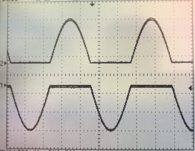
Note CH1 is flipped to better show the sine form.
also i cannot see a way to program the enable signals for the IGBT drivers that would be in perfect sync with the 3 output sines ( I guess i could do it analogically with some schmitt triggers and comparators but that would defeat the purpose of using a mcu altogether)
I have been playing with my code and design to see the symmetry and stability of the outputs but with only a 2 channel scope and 6 signals to measure i had to overlay multiple pictures in photoshop to show the output I’m getting.
which is this..
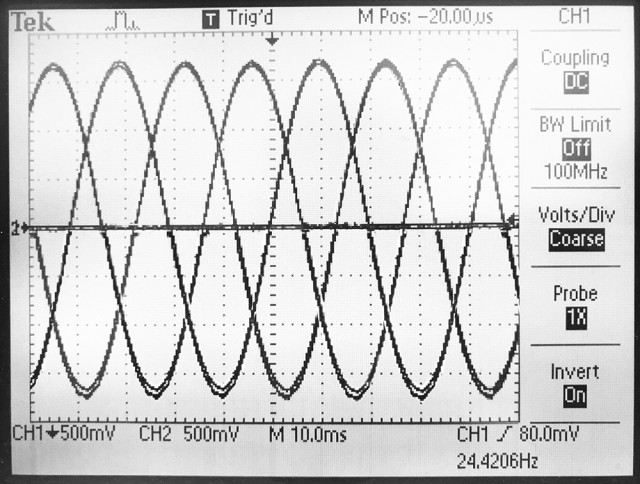
everything works nice except the fact that the max frequency i can get while doing two analog reads (one for amplitude and one for freq) is 415Hz. If i do not do any ADC the max frequency i get is 1.19KHz which is where i hope and pray that i can somehow use DMA for UART to send the variables for freq and ampl to the STM32.
i found this article but it is above my level of understanding
http://stm32f4-discovery.net/2017/07/st … using-dma/
Can someone please help me with this?
Thanks
The brushless motor Nidec 22H67 has 380 Hz @ 2400 rpm may by your 415Hz it is enough, unless you meed much higher RPM.
I am not familiar with linked stuff.
May be go to next step = IGBTs and make tests with the motor ?
Comparing Nidec(square wave ) and motor running on MTD6501C-HC1 (sine wave) the second one is running much smoother but this are small motors, to make Nidec working better I added to it a flywheel. In my case the smooth was main factor (Less than 0.1deg vibration), I dont think you need such precision.
No I’m not. The 6 signals in combination with the 3 sine wave signals, are needed to control the 6 gates in the 3 phase H-Bridge.
It could also work with 3 signals by using a different type of driver i guess.
But the question remains,
How can i accomplish this with your code for the sine generator?
do you have a schematic of how you drive your motor from your code?
the question is why not to use full sine from beginning , the problem with symmetry ?
because a full sine wave is not useful to drive the gates/drivers directly. I still need to break it into separate signals for the high side and the low side of the H bridge and to do that i need at least another signal that is in sync with the sine (I could accomplish this analogically but that, like I said, would negate the use of a MCU entirely and would be more complicated I think) In addition the need for symmetry and synchronization is much greater in a VFD of this type than say in a low voltage BLDC. (if there are problems you get unwanted losses and lower rpms in a BLDC but in a 240V AC motor you trip the breaker at best or start a fire at worst.)
The brushless motor Nidec 22H67 has 380 Hz @ 2400 rpm may by your 415Hz it is enough, unless you meed much higher RPM.
My motor is a 3.8Kw mains powered AC motor with a top speed of 40,000RPM
May be go to next step = IGBTs and make tests with the motor ?
I agree.
I do hope that someone here knows how to receive data via UART using DMA or maybe ADC using DMA??
[stevestrong – Mon Jan 21, 2019 10:53 am] –
Maybe is this post interesting for you: viewtopic.php?f=18&t=2743
Thanks That looks very clever.
And reinforces my belief that DMA is the way to go for me.
I found this post viewtopic.php?f=48&t=4399&p=51439&hilit=adc+dma#p51439 but it goes a bit over my head.
But be warned, several DMAs running simultaneously could eventually disturb each other.
Nidec has distortion on both edges of square wave, MTD6501C-HC1 is like trapeze not a pure sine.
Comparing the noise, Nidec is noisily (acoustic noise) , MTD6501C-HC 1 is very quiet = you can hear almost nothing even if you put ear to the body of the motor.
You can to this;
PWM to optocoupler > to gate of IGBT > to motor.
You don’t need high voltage filters, inductance of the motor will do that.
[stevestrong – Mon Jan 21, 2019 12:10 pm] –
There are some ADC + DMA examples in my repo for F4, you could maybe port them to F1.
That is very helpful thank you.
I have never ported code before but will get reading. Is it a complex procedure? I assume it is mostly about editing the STM32F4ADC.h?? Do you have any advice? or is it too much for a beginner like me to do?
But be warned, several DMAs running simultaneously could eventually disturb each other.
Ideally i would like to read two ADC channels but if it comes to it one would also be enough.
You have to dig deep, with the help of both reference manuals.
OTOH, DMA examples can be found in SPI library for F1.
For soft PWM output it has to be triggered by timer, and the destination address must be adapted as well.
If you have that, using DMA for ADC should not be that difficult, rather a good exercise.
But all these you have to do by yourself, I cannot do that due to lack of time.
I had a “look” through the library. It, unfortunately for me, is more than i can understand so I doubt i could port the code myself. I will keep looking for examples of ADC or UART with DMA for the F1.
Another option i guess would be to use an F4 board instead. Is there a bluepill type board with an F4 chip?
[FCam1 – Tue Mar 05, 2019 2:21 pm] –
I don’t know if you are always looking for a DMA UART TX example but I did that few month ago for a F103ZET6 : https://www.stm32duino.com/viewtopic.ph … art#p47489
Thank you
I will have a read.
Have you encountered a RX example anywhere. In my case i would need to only receive but I’m hoping that i can work it out using your example.
Some examples using DMA with ADC : https://github.com/rogerclarkmelbourne/ … C/examples
assuming that you need digital sine output (=pwm), not analog sine output.
here is what I would do.
1) have a sine duty table. 256 points for example. use a phase accumulator to index it.
2) set up 3 pwm output channels, ch1–3.
3) set up a timer interrupt and is invoked periodically.
4) in the timer isr, set ch1’s duty cycle based on the duty table, indexed at accumulator; ch2’s duty cycle indexed to accumulator + 256/3, and ch3’s duty cycle indexed to accumulator + 256*2/3.
with this approach, your main() loop is empty.
if you really need analog output, put a lpf on each of the digital output channels.
[dannyf – Sat Mar 16, 2019 12:51 pm] –
1) have a sine duty table. 256 points for example. use a phase accumulator to index it ?
You mean use 3 tables, two of them shifted ± 120 deg ?
I saw something like that somewhere.
The idea is simple, use 360 point table, each point is 1 deg.
Example for 10 deg. shift; remove 10 first points from table and put them on the end in reverse order.
[dannyf – Sat Mar 16, 2019 2:00 pm] –
why use 3 tables when 1 can do?
Many years ago (probably around 1990) I remember that the programmers only used the first 90 degrees of one sinewave in a table to create three phases.
