Video: https://www.youtube.com/watch?v=QE03CFNgCjA
code: https://github.com/ddrown/binary-clock
I also want to add:
– Timezone support with automatic daylight savings time
– either a wifi or ethernet NTP client to set the time / correct the clock frequency
– a nice case
* “binary” as in binary coded decimal – each field is split into two columns: the first one is the tens digit and the second is the ones digit. The video starts at January 17, 2016 02:59:49
BTW. If its a public video, you may want to write some notes including what board and display you are using as well as the library and also were to download the stm32 repo on github.
<…>
I also want to add:
– Timezone support with automatic daylight savings time
– either a wifi or ethernet NTP client to set the time / correct the clock frequency
– a nice case
* “binary” as in binary coded decimal – each field is split into two columns: the first one is the tens digit and the second is the ones digit. The video starts at January 17, 2016 02:59:49
<…>
Also, I’d love to use GPS to set the time for this project, but the place I have in mind has zero GPS reception. Thanks for the suggestion!
“zero GPS” is a definitive statement, like 0. Or, can you justnot get a GPS lock? Often, folks confuse the two. I have multiple GPS clocks here, one in the basement in my lab, near the center of the structure. I cannot get a navigational 3D lock, but I do get one or two of the satellites overhead even during rain and storms. My code does not require a 3D lock, just the serial output of the $RMC. But, if you really get 0, then I cannot help you with GPS
Ray
GPS Essentials app. GREAT app for Android.
On bottom floor of my two story home. Not near window. No mountains nearby (sky occlusion).
Dense suburban area.
Screen shows
10 sats visible, 6 used in fix. Varies of course, as sats move and conditions change.
GPS receivers work with a very low signal strength, like -120dBm due to “post correlation gain” that comes from use of spread spectrum signals with long code length.
then my app: GPS Essentials, says “No fix” and “Network locations disabled”, meaning it won’t use GPS or WiFi or cellular for estimates.
The satellites in view graphic still shows the last-received set of satellites, though I’d think these will age-away.
My choices are:
1. use the esp8266 module just for NTP, and use the stm32f103 as a rtc & lcd driver
2. use the esp8266 to do NTP&LCD, and don’t use a rtc
I have the LCD library working on the esp8266. Compared to the STM32, there’s more idle time between each SPI byte transferred. I assume because of interrupts, even though these tests have everything else disabled. But it still seems fast enough to possibly get the job done.
I ran my app on both platforms and compared how long it took to do each of the three screen updates. The app’s screen updates are: full screen redraw (at *:00 seconds), tens&ones column of the second redraw (at *:*0 seconds) and only the ones column redraw (every other time).
ESP8266: full screen ~300-400ms, tens&ones ~52ms, ones ~30ms
STM32: full screen ~50-70ms, tens&ones ~16ms, ones ~12ms
So you can see the STM32 is much faster at managing the LCD and the full screen redraw time is a problem on the esp8266.
What would y’all do? Two microcontrollers or one?
I supposed that because you need Wifi functionality and the ESP8266 can do it all, then the technically best solution is to just use the ESP8266 ..
Unless the SPI speed is causing any noticeable effect on the display.
It sounds like you don’t need to use a RTC as your system will have access to the net often enough and be powered all the time, so it doesn’t need to keep time when the power removed (the main use of the RTC IMHO)
BTW. If you are using SPI for the LCD it will be slow as AFIK on the ESP8266 its “Bit Banged” i.e software SPI not hardware SPI
If you have the ESP-12E it exposes the HW SPI pins, but I’ve not found Arduino code to use them (There is a parallel thread which also discusses SPI on the ESP8266, which Ray posted some useful information to)
<…>
I’m using the nodemcu board, which has a ESP-12E. ESP8266’s Arduino SPI library uses the HSPI peripherial: https://github.com/esp8266/Arduino/blob … PI/SPI.cpp
I’ve verified it can do 80MHz, 40MHz, and 26.6MHz SPI speeds on the scope, so it’s plenty fast when it’s clocking bits out. It even has a writebytes/writepattern function to send up to 64 bytes out at a time.
Excellent! How are you utilizing the port (for what peripheral device?) If for ILI9341, did you work through any example code? I asked because the forum published aspeed-chart using a test suite last year and it would be nice if the ESP8266 were added.
@ddrown,
Thanks.
I added a new function to the LCD library (Adafruit_ST7735): PixelArray. This takes x/y, width/height, and a pointer to the pixel color data. It streams that out SPI to the screen. I created bitmaps in flash in the correct color format. With these things, the esp8266 can stream the bitmaps directly from flash to SPI without processing. This was a huge speedup compared to using the drawCircle/fillCircle combo:
before: full screen+text = 300-400ms, tens seconds = 52ms, ones seconds = 30ms
after: full screen+text = 72ms, full screen-text = 11ms, tens seconds = 2ms, ones seconds = 1ms
Around 4 times faster. This also gives me the freedom to define other bitmaps. A full screen bitmap would be ~40kb, and my 16×16 pixel bitmaps are 512 bytes. So the 1mb flash can hold plenty of images.
So I threw in some USA holiday icons. In this video it’s just switching between them all every 4 seconds, but normally it’d only be on the day of the holiday.
Also, I did some work on the timekeeping parts. I created a function to adjust the rate of the clock by adding/removing milliseconds. I measured the drift of the clock of my unit and then hardcoded that rate (dynamically detecting and adjusting the rate is on my to-do list). It made a NTP request every 64 seconds for 24 hours and logged the offsets.
First run, against a local NTP server: 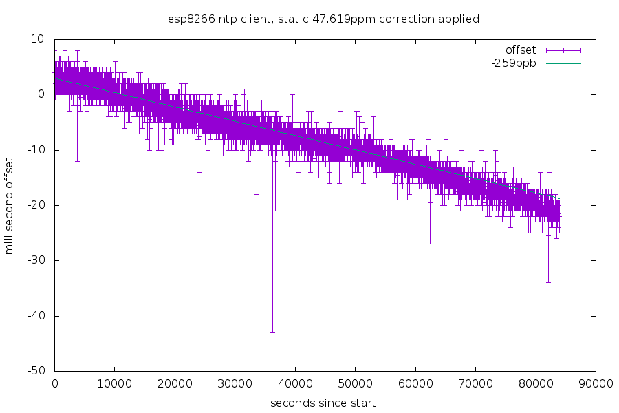
Second run, against my NTP server on the internet: 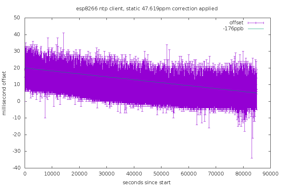
The height of the purple bar is the uncertainty in each measurement (the time it took from the NTP request to the response). The cyan line is my rough estimate of the drift rate of the clock. Each run was done on different nights, so the temperature difference is probably why they ended up at different rates.
Still many things left to be done!

