https://www.youtube.com/watch?v=l2rgkSTRw_s
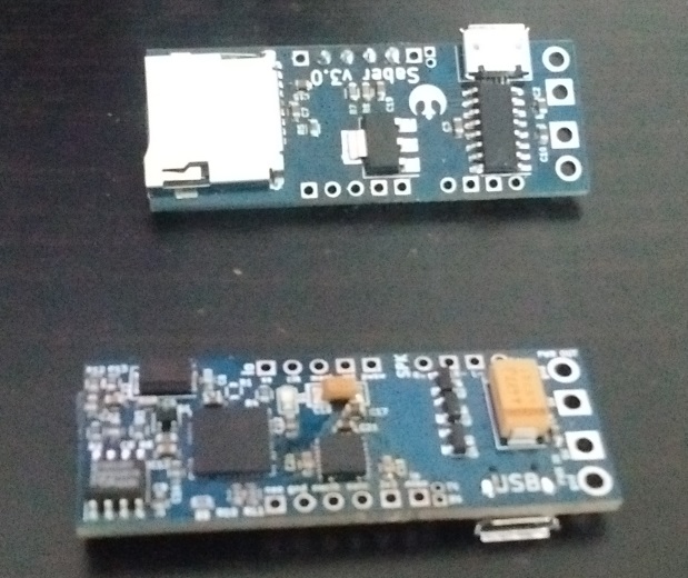
a maple mini controlling it all (and loving it for the extra flash memory that allowed me to store the 8 bit sound samples on it ![]() )
)
it uses ws2812b ledstrips for the lights (and i diffused them with some white foil, so irl you see the leds a bit, but it still looks very well)
and put a tda2003 amp and an 8bit dac in there to get some sound ![]() .
.
Glad i got it working well enough as the 7th movie is released ![]() .
.
on my todolist:
-replace the tda2003 with a small class D amp, will save me a lot of room, and it’s not as if i’ve got room to spare (the heat is okay, it’s only putting out about 2W, and has got a small heatsink on it, but still, in that small place…). and also put a better dac on it, 12 or 16 bit, i’ll see what i can find that looks good enough ![]() .
.
-add a motion sensor, and program it to detect swings & clashes ![]() (and maybe also a button so you can decide to play reflecting weapon fire sounds).
(and maybe also a button so you can decide to play reflecting weapon fire sounds).
-see if i can add an sd card for the sound samples, 120k really isn’t much space to play around with ![]() . certainly not if i want to add swing & clash sounds
. certainly not if i want to add swing & clash sounds ![]() .
.
It will act as a small amp and play the stored sounds. I don’t know how fast you can switch between sounds but it seems a cheep thing to use.
maybe add nrf24’s and mini somethings, send settings from wrist unit or do it with micro and buttons inside the grip?
on small spaces and heat
decades back i had honda cd175 with 6v battery
well it got modified with a halogen 12v headlight running off an inverter, diode bridge block was chunky
and as it rattled about a bit, a bit of rag got chucked in the space with it.
70mls down the M6 whilst in the outside lane, i had a rather spectacular 12″ square plume of smoke pouring out the side panel.
now in order to get to that space requires removal of the seat, held by 2 severely rounded 13mm head bolts,
removal of tank as in petrol and i had to take all my luggage off to start.
then i just grabbed the flames and heaved; ruined my gloves.
it ended with the bike 3/4 in and the rest hanging out the boot of a very big booted car, driving round Birmingham looking for a complete wiring harness. (there used to be a large industry supplying all sorts of ‘patent’ bits for motorcycles, name?????)
stephen
It will act as a small amp and play the stored sounds. I don’t know how fast you can switch between sounds but it seems a cheep thing to use.
It will act as a small amp and play the stored sounds. I don’t know how fast you can switch between sounds but it seems a cheep thing to use.
srp
srp
srp
srp
Re:Amplifer
I have been converting an old good quality hifi speaker to bluetooth and I’m using a cheap class D samplifer from ebay (TDA7297), and it does not get very hot at all.
However to get loud sounds you will need a good battery and a bigger battery.
Take a look at @ahull’s thread on low cost power supplies using various lipo cells.
I recommend using 3 lipos in series to run the amplifier.
Re:Motion sensor
The MPU9150 is a good sensor, (I2C) I tested it with the Maple Mini a long time ago, but never got around to using it in a project ![]()
i have some MPU-6050 boards, which apparantly are a predecessor of the MPU-9150. All it lacks is a magnetometer, which i don’t really need. The weakness of the mpu-6050 is that you can’t detect drift (which you could use the magnetometer for to compensate), but i don’t think i’ll need such detailed motion sensing.
i have some MPU-6050 boards, which apparantly are a predecessor of the MPU-9150. All it lacks is a magnetometer, which i don’t really need. The weakness of the mpu-6050 is that you can’t detect drift (which you could use the magnetometer for to compensate), but i don’t think i’ll need such detailed motion sensing.
As you may have read in my other threads (http://www.stm32duino.com/viewtopic.php?f=27&t=862), i’ve been hard at work at making dma libs for improved IO performance, so i can take my saber a few steps further ![]() .
.
After tons of work, my code has finally surpassed the abilities of the first saber i made ![]() . It’s too early to build it into a saber, but i’ve got a proof of concept running that is finally bringing it all together
. It’s too early to build it into a saber, but i’ve got a proof of concept running that is finally bringing it all together ![]() .
.
Current progress:
– I can load soundsamples from an SD card onto a flash chip, with a little ‘filesystem’ i made so i can easily read those samples from the chip.
– I can send data to the neopixels via the SPI port, which i address via DMA ![]() .
.
– I can send 12bit soundsamples to an i2c dac, at a max sampling rate of 60khz (when overclocking the port to 1.2Mhz), but the samplingrate is variable (so the sound can react to motion ![]() ) (more info here: http://www.stm32duino.com/viewtopic.php?f=19&t=1048)
) (more info here: http://www.stm32duino.com/viewtopic.php?f=19&t=1048)
– I can read an I2C motion sensor via DMA calls, and extract useful data from it (well, i think it’ll be useful XD).
My current proof of concept is the first 3 combined and working perfectly ![]() .
.
the soundsamples are going out steadily (at about 16khz atm). the sound is coming from the flash memorychip, which is streaming it in blocks of 128 bytes, and at the same time the 144leds neopixel string is updating about 200 times per second ![]() . Both the I2C port for the dac and the SPI port of the neopixel string are sending data pretty much continuously, and when required the next block is requested from the flash chip
. Both the I2C port for the dac and the SPI port of the neopixel string are sending data pretty much continuously, and when required the next block is requested from the flash chip ![]() .
.
-> my first saber couldn’t come close to that refreshrate of the neopixels, had to read the sound from its internal flash memory (so very limited in how much sounds i could have), had an 8bit parallel dac so i didn’t have overhead of the serial protocols ( i just connected it to one of the ports of the maple and set the samples on this port), and when doing all this was completely swamped since it was doing all the timing manually ![]() , and driving the neopixels via bitbanged code
, and driving the neopixels via bitbanged code ![]() .
.
TODO this weekend (maybe), try and also add the motion sensor so i’ve got my 4 devices running at the same time and doing what they should be doing ![]() .
.
I think it’s great how much IO you can get from this little maple mini ![]() . When i started it seemed like a near impossible project, but i’m slowly getting there
. When i started it seemed like a near impossible project, but i’m slowly getting there ![]() .
.
(and for those wondering, the SD card is only used for filling the flash memory, streaming from an sd card felt slow & hard to work with).
lightsaber test
quite pleased with how it now reacts to motion ![]() . Gives it a really natural sound XD. I still have to implement collisions, add some way of selecting sounds/colors, do some hardware improvements, …. but it’s getting better with every iteration
. Gives it a really natural sound XD. I still have to implement collisions, add some way of selecting sounds/colors, do some hardware improvements, …. but it’s getting better with every iteration ![]() .
.
Are projects ever truly done? ![]()
it’s a little custom pcb with an stm32f411, a motion sensor, an I2s DAC, a micro sd card holder, and some usefull pins broken out (the SWD header, one of the usarts, some pins for whatever else i need).
I’m wondering how this will turn out ![]()
And for now, i’m really liking KiCad. When first looking into pcb’s i gave eaglecad a try, but didn’t quite like it. with the recent thing with their licenses my motivation for learning eaglecad shrunk even further >_<. so i decided to give KiCad a try, and i’m really liking it ![]() . already made my own footprints and everything, and i really like working with it
. already made my own footprints and everything, and i really like working with it ![]() .
.
What sort of cost & turnaround time were the prototype boards?
What sort of cost & turnaround time were the prototype boards?
My last board was done in KiCad, which felt a bit strange after using Eagle for several years.
The main difference is symbols dont have automatic linkage between schematic representation and PCB footprint, and to start with, I thought this was a retrograde step.
But after a while it started to make sense to only link the footprint when in the PCB design program
I don’t know if they added it in the last couple of months, since I last used KiCad, curved tracks were not possible, but that was the only feature I used in Eagle that was not in KiCad
KiCad is no worse. But perhaps some of the expensive packages like Altium are better and thats what they could be comparing it with (though it seems unlikely)
submitted the files yesterday, today got an update that the pcb is in production ^^
RogerClark wrote:I never found the UI on Eagle that good
KiCad is no worse. But perhaps some of the expensive packages like Altium are better and thats what they could be comparing it with (though it seems unlikely)
I suppose Eagle has an Autorouter, but I found it was only useful, if I first did some of the tricky routing myself, and it still ends up spraying the board with vias etc
So manually routing my last board ( a home project) using KiCad was not a problem, as it would have been impossible to use the Aurorouter in Eagle! as I had 5mm wide mains power tracks that needed to be routed on the too and the bottom of the board in parallel, as it needed to carry a lot of current, and I also had to ensure the mains isolation spacing between the tracks as well etc etc
One of the other reasons I moved to KiCad was the limited board size on Eagle, on the Free and the basic Commercial version.
I paid for the basic commercial version ( around $100), but you are still limited to the same board size as the free version.
If you want to make a board bigger than 100mm in width or length, you need to shell out $1000 or more for the next level up.
This is still the case even now Eagle has been bought by Autodesk ( I checked a few weeks ago)
So I cant make a long thing board with Eagle.
Hence I jumped ship, so I can make boards 110mm by 50mm etc in KiCad if I want to ![]()
After a lot of struggling (and having made the stupid mistake assuming the tab on the ams1117 is connected to ground, it’s not :p), i’ve got one of the boards blinking its led using the stm32f411 that’s on it XD.
i’ll still have a lot of work getting this little thing completely up and running, but it’s a good start XD. i’m already amazed that besides the stupid voltage regulator error (which was easily solved using some heatshrink around the tab, and we’ll see how it does with heat, it’s a low power board, so maybe it’ll manage like that :p ), i haven’t encountered any other mistakes so far
on to the next adventures with this little board XD.
i’ve got the impression it’s currently running a bit too fast, so that’s the first thing i’ve got to investigate (it’s using a 24Mhz crystal)
*edit* fixed ![]()
found where in the cubemx code where it was still thinking i had an 8 mhz crystal ![]()
now the led is blinking as expected, and this little board is slowly becoming usable ![]()
– everything seems to be working on the board (sound is ok, microcontroller is ok, motion sensor acknowledges on its i2c address, sd card works on its 4 datalines, and the led works
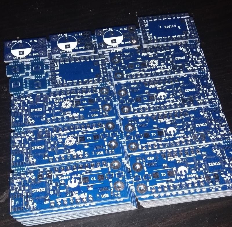
so i’ve designed some new boards to test with:
– the same board with the error & some annoyances fixed
– a board with slightly increased functionality (a mosfet to switch of powerhungry (=sd card & DAC) parts of the board & a micro usb port iso just a plain usart port), and smaller formfactor (33 x 18 mm)
– a board about equally large (48×18 mm) as the original one, also containing the above improvements, and additionally a high power part where the pam8403 amplifier is also on the board, +3 mosfets that should be able to switch on/off the ledstring (on the same channel as the mosfet for switching of the other parts).
And sent these of to china yesterday to have produced ![]() .
.
I’m wondering how those boards will turn out
besides that, i’m now returning to writing code for the current board to get a working lightsaber system on this board. So far i’ve already adapted the HAL I2S driver to work how i need it (it fetches samples under interrupt), so i’ve got a working sound layer (supports 8 a 16 bit sound at 8, 16, 24 & 48khz. The DAC is a 16 bit DAC running at 48 Khz). Now starting writing code to read FAT32 under DMA, similar to my streaming system i had on my previous saber that was streaming data from an SPI flash chip. and then i’ll port my mpu6050 code to this project, and slowly come to a working saber again ![]() .
.
srp
srp
– the same board with the error & some annoyances fixed
– a board with slightly increased functionality (a mosfet to switch of powerhungry (=sd card & DAC) parts of the board & a micro usb port iso just a plain usart port), and smaller formfactor (33 x 18 mm)
– a board about equally large (48×18 mm) as the original one, also containing the above improvements, and additionally a high power part where the pam8403 amplifier is also on the board, +3 mosfets that should be able to switch on/off the ledstring (on the same channel as the mosfet for switching of the other parts).
And sent these of to china yesterday to have produced
the streaming from SD is done via DMA in blocks of 2kb, sending to the I2S is via interrupts
*small edit*
continued a bit on it (it was still a bit noisy), fixed all the errors in the code, and i’ve now got very good playback ![]() .
.
this thing is working XD.
just ported the mpu code to HAL, and got that now working too
the pieces are slowly coming together
that’s a good basic program to start from for developing a nice lightsaber program
and that also means everything on the first pcb i made is working XD
wheeee
Or know of any neopixels code that works OK?
I’ve been trying to use a port ( https://github.com/ANDnXOR/Adafruit_NeoPixel-ANDnXOR ) , but it seems to have a lot of problems, with the pixel data generation, where it ends up just turning every LED to 255,255,255 or 0,0,0 rather than the value I requested.
I guess perhaps it could also be a problem with the LED strip, as I bought it from a local supplier on eBay, who probably imported it from China as cheaply as possible.
I’ve modified the maple port of the Adafruit lib,and it now works OK.
I have also now tried to use SPI, but I’m having problems with the first pixel ![]()
I’ve modified the maple port of the Adafruit lib,and it now works OK.
I have also now tried to use SPI, but I’m having problems with the first pixel ![]()
I think I’m doing the same thing you did
Set SPI for DIV 32
then write 100 for a 0 and 110 for a high
So you end up with a buffer which is 9 x larger than the number of pixels, as it takes 3 bits per colour bit.
Strangely its just the Red channel that has problems (i.e the middle channel)
I originally tried a port of the Adafruit lib, which bit bangs the data, but it kept doing very strange things, and when I looked with my logic analyser I found the timing was beyond or at the limit of the spec.
So I re-wrote some of it to use asm “nop”s as delays and improved the code that used BSSR port.
This now works OK, but using SPI and DMA looked like a better solution, so I’ve written an SPI implementation, and it almost works, but not quite.
The red channel of the first pixel, seems to be shifted so that if I write 0x01 into red I get 0x80 in Green
But only in the first pixel.
I do have a Saleae analyser clone, so I’m now trying to compare the bit banged version, which works with the SPI one that doesn’t
In this code, i’ve encoded 1 neopixel bit to 4 bits in the spi (3 bits is also possible, but requires a bit more work to convert, and on an stm32f4 i’ve got enough RAM to not bother).
It means i made a lookup table that converts a byte to an int32 which contains the neopixel signal for that byte
And in this code you can also see i add an extra 4 bytes containing zeros to flush and to not have the first pixel issue.
I hope this helps you a bit further ![]()
I’m slightly confused about the protocol
Reading the data sheet https://cdn-shop.adafruit.com/datasheets/WS2812B.pdf
The the MS bit is sent first (bit 24 ) then and the bit colour order is Green, Red, Blue so the first bit is the MS it of green
The strange thing is that it looks like each pixel reads in its own data and does not pass that data out, but waits until its data has been locked and then passes all subsequent data to the next pixel (and so on)
So the first pixel that is sent, is the data for the end of the strip where the data is initially input.
The other odd thing that I’m seeing using SPI.dmaSend() is some garbage at the beginning, which doesnt look like my data at all, so I don’t know where its coming from.
This one is the Bit Banged version which works, and the first LED is off
- bit_banged.png (7.5 KiB) Viewed 416 times
Fixed it.
Made the whole DMA buffer 1 byte longer, and made sure the first byte is zero.
Then adjusted the code so that everything offsets 1 byte after the start of the buffer apart from the dmaSend
Edit.
I’m not sure its completely fixed, as it looks a bit different from the bit banged version, so I’ll need to run some more tests, but at least I don’t get the huge problem with the first pixel
it very well explains how they work and which timings are needed
I think something is still wrong with the green channel, but Hopefully I can fix it.
BTW.
Did you use SPI DMA for your version?
I think something is still wrong with the green channel, but Hopefully I can fix it.
BTW.
Did you use SPI DMA for your version?
In theory the timing should be within spec, as each bit sent via SPI is 444nS long, and the shortest bit duration can be 250nS to 550nS
On the 100MHz logic analyser, I’m seeing variation of pulse width of 10nS, but that is just going to be the sample resolution of the analyser.
But the very first “bit” of data sent by SPI always seems longer, at around 490uS, which was the cause of the Green LED turning on.
Sending a first byte containing 0x00 fixed this.
BTW. Thanks for the link. Very interesting.
Basically, its only the length of the High pulse that is critical, and determines whether the “pixel bit” is 1 or 0.
i.e the LEDs are not comparing the mark/space ratio to determine if its a mark or a space.
This explains why the bit banged implementation seems to work ok, even though the length of the Low part of the bits is not super accurate.
Also the reason only the first pixel seems to be problematic, is according to the article , that the first pixel is cleaning the data and resending it.
BTW.
I see the Teensy can DMA 8 strings of LEDs at once, so I wonder how this is being achieved. I presume its using a similar principal, but DMAing to GPIO, 1 byte wide. But the Teens code seems to be part of the Teensy installed suite and mot available elsewhere eg. github.
I may look for an ESP8266 or Arduino Due etc implementation and see how they do it
http://www.martinhubacek.cz/arm/improve … 2b-library
It seems to be able to DMA multiple strips via DMA.
It may be compatible with one of the HAL based cores.
But for a single string I think that the size of the data would be unnessecarily large
I think I may start a new thread for this subject on its own
I’ve also been messing around with doing asynchronous dmaTransfers to improve the speed, and I’ve added a new function to SPI called dmaSendAsync
This function is not used in the library, but what it does is start the dmaTransfer then exit the function, so that the main code can carry on and do other things.
Then when you call dmaSendAsync, it checks if the transfer is still in process, in which case it waits for it to finish before setting up a new transfer
However I’d need to use double buffering in the library to support this, – which I’ve not written yet.
and the other link you sent with the timers & multiple dma’s is insane XD. i’ve yet to learn how to use such features (although i’ve recently for the first time done dma triggered by a timer for adc sampling, but it was a frustrating exercise).
And as you can see in my code, i’m using the fact that the low signal can be a bit longer to use 4 bits per signal in my SPI generator, and i can then simply convert a byte i want to send to the string to an 32bit int via a small lookup table (1kb in size), and then you can very quickly convert a framebuffer containing rgb values to a buffer containing the neopixel signal
I use LUTs to work out the values needed for my 3 bits per bit system
I could make the LUTs smaller, and I left the small LUTs in the code, but it would run slower as I’d need to do masking and shifting, and it would take longer to send, so 3 bits works OK for me
I’ve recently received some great solder paste (loctite GC-10), and it’s working really well ![]() . Been improving the stencils for soldering SMD i make a bit (for the MPU6050 it gave me too much paste, giving shorts when soldering), and i’m now getting pretty decent results when populating & reflowing the pcb’s (atm still reflowing the pcb’s in a skillet. looking into building an own oven, but the skillet method is also working pretty well
. Been improving the stencils for soldering SMD i make a bit (for the MPU6050 it gave me too much paste, giving shorts when soldering), and i’m now getting pretty decent results when populating & reflowing the pcb’s (atm still reflowing the pcb’s in a skillet. looking into building an own oven, but the skillet method is also working pretty well ![]() )
)
- pcbs.jpg (112.3 KiB) Viewed 516 times
Was struggling with the sd cards a bit, but it ended up actually being an sd card that was broken ^^’. (i’ll have to keep an eye on it if i break any more sd cards while using these board ![]() ).
).
but pretty happy these little guys are working XD.
[racemaniac – Thu Aug 17, 2017 6:05 am] –
Another small update: tested everything except the USB so far on the above boards, and it’s all good XDWas struggling with the sd cards a bit, but it ended up actually being an sd card that was broken ^^’. (i’ll have to keep an eye on it if i break any more sd cards while using these board
).
but pretty happy these little guys are working XD.
I would love to build one of these. do you plan on releasing the source code/schematics?
any chance of a video ?
set of nice photo’s ?
stephen
the current source code is just setting up everything and doing basic tests (playing some music, using the motion sensor to light the led when the board moves, doing a test pattern on a few leds). This is enough to know it all works, but not much of a program yet.
and the only video i have is thus the board playing the starwars soundtrack
v4 of the boards just shipped, i hope that will be the final revision, i think it’s compatible with the v3’s, and once they arrive, i’ll assemble a few, and start building a real lightsaber and some proper software to drive these boards XD.
and atm this project is more about learning how to make pcb’s & how to solder them than it is about lightsabers XD. but the end of that tunnel is finally approaching, and then i can put all my attention again on making it a nice lightsaber XD.
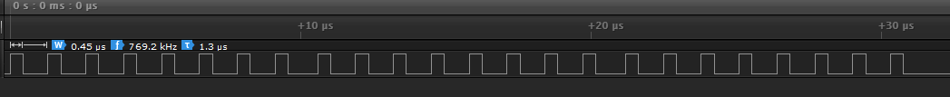
I was just testing and I can go up to 1.3Mhz. Over that either it slows down, or directly stops working.
[victor_pv – Tue Sep 12, 2017 4:49 am] –
Slightly offtopic, what’s the max speed at which you overclocked the i2c interface?
I was just testing and I can go up to 1.3Mhz. Over that either it slows down, or directly stops working.
i got up to 1.2Mhz, and then it stopped working for me (not sure if the stm32 or the DAC was the issue)
I suspect the limit is the MCU since we both hit it at around the same speed.
looking forward to assembling a few of these, and have a look at how well they work
besides the lightsaber boards, the panel also contains 2 small boards which are very minimal stm32f103c8t6 boards (just the stm32, with decoupling caps, a resistor to pull boot0 down, and a button on the pcb, and the pins that i was interested in broken out). It’s made so that it can be connected to the main lightsaber boards, and have them communicate via SPI. not sure if i’ll need it, but it’s not much work to make.
and besides that some small boards for putting decoupling caps on the neopixel power supply cables, and some adapters for ams1117 -> ap2112k. i like the maple mini, but the ams has to go :p. so i made some adapter boards, now i should be able to replace it by an ap2112k, which seems to be much better up to the task ![]() .
.
- pcbv4.jpg (179.09 KiB) Viewed 407 times
looking pretty good
besides that, everything seems to be working (i still have to test usb, but sd card, sound, motion sensor, … are all ok).
still really happy with the ability to cut my own stencils using a silhouette portrait cutter ![]() . and the loctite solder paste is great
. and the loctite solder paste is great ![]() .
.
applying the solder past stencils is still a delicate job, but when i carefully do it, and i get a really clean result, it’s awesome to see (ans also nice to see even the QFN chips solder nicely without shorts then ) ).
[zoomx – Mon Nov 06, 2017 2:41 pm] – Well done!
thanks ![]()
now back to improving my software for the board ![]()
did some test in mixing multiple soundchannels, and it was a bit slow. So now rewriting that part (now working with the i2s in a circular dma loop, and using the xfer half complete & xfer complete interrupts to fill in parts of the buffer, so i can do it in larger (and hopefully more efficient chunks), not sample per sample as i was doing now ![]() .
.
i was already able to mix 2 48khz channels together, a 3rd channel was too much ^^’.
i’m also considering making a “dev” board of this: a larger version, with all interesting points to measure easily reachable. then when working on it, i can hook up a logic analyzer to the digital signals i want to investigate, hook up a oscilloscope to check the analog parts, etc… ![]() . it’s sometimes annoying when working on it that i can’t easily measure all those things ^^’. on such a small board, nothing is easily reachable >_<.
. it’s sometimes annoying when working on it that i can’t easily measure all those things ^^’. on such a small board, nothing is easily reachable >_<.
Took me Waaaay too long yesterday to get the filestreaming from fat32 completely working (was wise enough to write a proper test so i could find any and all errors, and boy, i found them all XD). Somewhere in the future i want to come back to this as i finally have a good view on what’s required to stream multiple audio channels from a sd card and be able to mix them
For those interested, my current system (let me know if you know of better ways):
Memory arrangement:
Per file i stream, i’ve got the following buffers:
– FileStart
– Buffer1
– Buffer2
– Buffer1StartRepeated
the reasons for these buffers:
– buffer 1 & 2 are just standard double buffering, nothing special
– the filestart buffer, is for supporting looping the audio. The last buffer i fill can literally contain 1 sample, so if i don’t have the start data ready, i’m screwed.
-Buffer1StartRepeated: The only way i can get good performance, is if i can just take a pointer to a block of samples, and can just use them, not having to switch to another buffer midway or so. Since i sometimes get offsets (file header, file not repeating in exact multiples of the blocksize i’m streaming in, …), i can want the data at the start of buffer 1 to be behind buffer2 so i can just give a pointer near the end of buffer2 and know the start of buffer 1 is also after it in memory.
Currently the above buffers are all 4K in size (this is how much data i request per call to the sd card), except for the repeated part which is as large as the blocks i request from this streaming system(this is half the size of the I2S buffer, currently 256bytes).
How it works:
Upon loading a file, you load the startbuffer & buffer 1 (and technically should fill buffer1start repeat to, but i won’t have such short files and i’m being lazy :p ).
The I2S port is in looping dma with half transfer & tranfer complete interrupts on.
On each of the above interrupts, you read a block from the files, and can then know it is contiguous sound data, no catches, so just add the data together according to volume of each channel, and copy it to the I2S buffer.
As you move from one sd card block to the next, as in standard double buffering, the other buffer gets loaded. If buffer 1 gets loaded, after its load it also triggers a memory 2 memory dma to fill in the repeated buffer part.
As the last block of a file is loaded, after its end a part of the startbuffer is copied behind it, so you can loop the file seamlessly (if you don’t want to loop the file, and empty buffer could also be copied after it to make sure it only returns 0).
That’s the basic operation.
Everything is running on DMA (I2S is in a DMA loop, for SDIO i created a queue of DMA calls so whenever a new chunk if data is needed, the system adds a call to be done to the queue, the memory copies for the repeat of buffer 1 & the copying of start data is a memory2memory dma call (should also make a queue for that)).
besides the above high level stuff, there are also nasty things such as offsets compared to the buffer you develop and have to take into account, which really gave me some frustrations to get it completely running without errors ^^’.
Currently the code is a bit atrocious ^^’, but at least it’s working XD. It evolved trough a lot of getting stuck at points, noticing what tanks the performance (basically anything you have to do per sample. If i work in blocks of 128 samples, any extra instruction there is just killing the performance. I now went for a solution where i could just take the data, know it’s consecutive audio data, and not have to check anything at all, just read the buffer and be done with it XD.)
I can now successfully stream four 16 bit stereo 48khz audio files simultenously without issues ![]() . goal accomplished ^^.
. goal accomplished ^^.
![[Pending Enhancement] RTC values resetting](https://sparklogic.ru/wp-content/uploads/2019/11/nucleo-l476rg-zestaw-startowy-z-mikrokontrolerem-z-rodziny-stm32-stm32l476-90x90.jpg)