Tell me, how do I make the most correct configuration for my task?
I want to learn how to program the USB port on the low level, so I can not use it to load programs.
As far as I understand, I have several options, and I want to choose the most convenient.
- Obviously, I can load the program through internal bootloader of BP. Most likely, this will require some kind of a hardware add-on, for supplying the reset and switching boot0.
- It’s also certain that I can use swd. But how suitable adapters are supported by Arduino-IDE, and will they work in automatic mode?
- Probably, it is still possible to install in the BP a bootloader from Arduino, designed for a serial port.
Still it would be desirable to observe some conditions.
- I want the serial port to retain the ability to be a debug-monitor console. The Arduino boards on Mega series processors do not have this problems.
- I do not want to move from my favorite Mac to another platform.
I apologize if I want indecently a lot.
Ogogon.
http://wiki.stm32duino.com/index.php?title=Blue_Pill
Years sgo, I found lots of low-level USB info on: https://www.obdev.at/products/vusb/links.html
However, one of our members has done a HID lib implementation… check that out:
http://stm32duino.com/viewtopic.php?t=2926
USB is not impossibly hard, but it is somewhat difficult. If you become frustrated with conflicting info or enen lack of information, then USB may be something to put off until you are more comfortable with STM32Fxxx.
Ray
[mrburnette – Mon Aug 27, 2018 2:35 am] –
The WiKi should be your 1st go-to place:
http://wiki.stm32duino.com/index.php?title=Blue_Pill
Thank you!
I looked at this resource, but only the third option from my question is described there. Installing the bootloader from Arduino.
Maybe I’m wrong in that I want to choose the first method, but it seems to me more elegant. Nevertheless, a ready-made processor loader is used, its own.
Is there something wrong with him? Arduino-IDE can not be adapted to it?
Honestly, I did not search answer of this question. But still, is it possible to configure the IDE so that for a particular board, or a subset of the board, it changes the mode of opening the serial port? On another exposed on it hardware signals (RTS, DТR)? Perform the specified delay?
A one Chinese guy published an article with a simple and clear name – 关于CH340在STM32实现一键下载电路的研究.
In it, he gives his version of a close-by-logic operation of the electronic circuit.
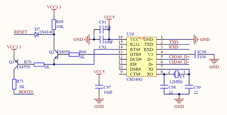
I did not quite understand why the emitter of the Q2 transistor is not connected to the ground.
But the rest of the principle is clear – RTS turns the processor into a programming mode, DTR – some strange reset, without them both – just a com port.
I believe that instead of Q3 you can put a digital transistor. Obviously, instead of Q2 can apply classical arduino’s solution with a capacitor.
And then it remains to configure IDE.
Ogogon.
With the housecleaning out of the way, I think these two posts will provide some background from past discussions;
The various upload methodologies generally available are explained here:
http://wiki.stm32duino.com/index.php?ti … g_a_sketch
Please do not make uploading sound difficult – it is not. Select what works for you, stay with what works.
Ray
[mrburnette – Mon Aug 27, 2018 8:07 pm] –
Please do not make uploading sound difficult – it is not. Select what works for you, stay with what works.
I ask to forgive me, but in school, technical school and institute I learn traditional English. As you speak – English English. And in any case, I can not fully understand.
Therefore, unfortunately, I did not understand the meaning of this remark.
If because of me your system can not upload audio files – please report why this is happening. I will immediately make every effort to eliminate this.
If this is some kind of аmericanism, a figure of speech, then please explain its meaning, so that I understand.
Ogogon.
[ogogon – Mon Aug 27, 2018 10:35 pm] –[mrburnette – Mon Aug 27, 2018 8:07 pm] –
Please do not make uploading sound difficult – it is not. Select what works for you, stay with what works.I ask to forgive me, but in school, technical school and institute I learn traditional English. As you speak – English English. And in any case, I can not fully understand.
Therefore, unfortunately, I did not understand the meaning of this remark.If because of me your system can not upload audio files – please report why this is happening. I will immediately make every effort to eliminate this.
If this is some kind of аmericanism, a figure of speech, then please explain its meaning, so that I understand.Ogogon.
No problem. ..
“Please do not make uploading sound difficult – it is not.” Translate to “… it is difficult if you make it so…”
“Select what works for you, stay with what works. Translate to “… multiple upload options exist, but not all options may work in your situation. When one discovers an upload method that works all the time, it is good to use that method all the time and not to become frustrated with further searching.
Your English is very good, I should be as fortunate. We Americans are taught English, but few really ever learn the language.
Good luck,
Ray
you want to upload your program via not USB ???
You can upload your via UART serail on pins PA9 and PA10 but you will need the external serial to USB converter something like this https://www.aliexpress.com/wholesale?ca … ial+to+usb
here is a youtube video on setting up ardunio IDE https://www.youtube.com/watch?v=MLEQk73zJoU&t=244s
You can also upload programs via SWD but ardunio doesn’t make use of this option and is only possible by using different IDE other than ardunio.
“I did not quite understand why the emitter of the Q2 transistor is not connected to the ground.”
This is to ensure the reset is triggered only when BOOT0 is pulled high.
[hobbya – Tue Aug 28, 2018 8:05 am] –
@ogogon
“I did not quite understand why the emitter of the Q2 transistor is not connected to the ground.”This is to ensure the reset is triggered only when BOOT0 is pulled high.
I apologize, but in that case I do not understand the depth and grandeur of this idea.
From my practice, it follows that the BP does not immediately respond to switching the jumpers bootX. To do this, you need to give a Reset signal and then the current installation of jumpers will be accepted.
If the reset will only take place in one of the jumper boot0 positions, then the BP will never be able to get out of this state?
Or I do not understand something, or this is not a solution to the problem.
Obviously, you need to reset after any change state of the signal that controls the boot0 switch.
Ogogon.
[flyboy74 – Tue Aug 28, 2018 6:22 am] –
I think I understand what your asking.you want to upload your program via not USB ???
You can upload your via UART serail on pins PA9 and PA10 but you will need the external serial to USB converter something like this https://www.aliexpress.com/wholesale?ca … ial+to+usb
here is a youtube video on setting up ardunio IDE https://www.youtube.com/watch?v=MLEQk73zJoU&t=244s
You can also upload programs via SWD but ardunio doesn’t make use of this option and is only possible by using different IDE other than ardunio.
Thank you!
This is the serial-TTL adapter I use.
The link to the video was useful to me. It demonstrates exactly the scheme I wanted to implement – using own bootloader of BP.
But still, there is one imperfection in it – switching is performed not automatically, but manually.
I believe that it is necessary to make a certain univibrator, which will be triggered from the front and the decay of the signal, which switch boot0.
The output of the univibrator will pull to the ground the signal RESET (or strictly speaking NOT-RESET). The end of univibrator impulse will process the start with the new parameters.
Ogogon.
The output of the univibrator will pull to the ground the signal RESET (or strictly speaking NOT-RESET). The end of univibrator impulse will process the start with the new parameters.
yes quite possible. I do not know the circuit used for blue pill but ESP uses this circuit to auto select boot
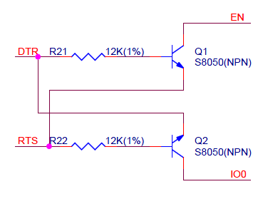
- esp32.png (11.78 KiB) Viewed 205 times
I put the jumper in boot mode then write my code and compile and download, once the download is finished it will execute with out needing to move the jumpers. When I make a change to my code I just press the reset button and it goes back into boot mode ready to accept the flash of code. Once development is finished then I remove the boot jumper so on power up of the blue pill it will execute the code in flash rather than go into boot mode.
The other option that is even better is to use the SWD pin for upload as it can reset and select boot as well as run a OCD (on chip debugger) but Ardunio IDE doesn’t support this and you will need to change to a different IDE (this is what I did), I am now using system workbench.
[flyboy74 – Wed Aug 29, 2018 9:52 pm] –
<•••>
The other option that is even better is to use the SWD pin for upload as it can reset and select boot as well as run a OCD (on chip debugger) but Ardunio IDE doesn’t support this and you will need to change to a different IDE (this is what I did), I am now using system workbench.
… which is all fine & well except you are now unsupported in the forum for IDE issues, reset issues, IDE install and usage,metc.. For those, like yourself, who are self-sufficient then your path may make good sense. For other members, it could spell trouble. It is not improber to suggest such an environment, but I and other moderators would appreciate a caveat explaining the “downside” as well as the upside.
Ray
[mrburnette – Wed Aug 29, 2018 10:03 pm] –[flyboy74 – Wed Aug 29, 2018 9:52 pm] –
<•••>
The other option that is even better is to use the SWD pin for upload as it can reset and select boot as well as run a OCD (on chip debugger) but Ardunio IDE doesn’t support this and you will need to change to a different IDE (this is what I did), I am now using system workbench.… which is all fine & well except you are now unsupported in the forum for IDE issues, reset issues, IDE install and usage,metc.. For those, like yourself, who are self-sufficient then your path may make good sense. For other members, it could spell trouble. It is not improber to suggest such an environment, but I and other moderators would appreciate a caveat explaining the “downside” as well as the upside.
Ray
ok I should maybe word it different
The other option that is even better is to use the SWD pin
maybe
A other option is to use the SWD pin
and of course this means that you can’t use any of the arduino higher level libraries just standard low level C
I believe that I already have an understanding of this aspect to a large extent.
Ogogon.
