I cleaned it with iudustrial alcohol and resoldered pins of stm32f103c8t6, it remains.
I set PC13 to output, high in the sketch, and it has no effect.
UART1, USB are normal
PA1~PA5, PB3~PB7, PA13~PA15 OUTPUT are tested, their output are normal.
Any clue to find the shorted cause?
Could I continue use the board?
PC14 is connected to the 32kHz resonator (and via 22pF to Gnd).
from an eon ago, apply 5v 40A psu in appropriate manner. it worked then, 74ls157 istr on tangerine 6502 eurocard. the trace it blew led me to a short across two pins of a dip package.
stephen
from an eon ago, apply 5v 40A psu in appropriate manner. it worked then, 74ls157 istr on tangerine 6502 eurocard. the trace it blew led me to a short across two pins of a dip package.
stephen
from an eon ago, apply 5v 40A psu in appropriate manner. it worked then, 74ls157 istr on tangerine 6502 eurocard. the trace it blew led me to a short across two pins of a dip package.
stephen
stephen
stephen
you could list it to the screen, nothing is quite like paper though
i think i offered it to microtan, but they (were doing) or did their own version, but then again i didn’t need to buy it!
stephen
PC14 is connected to the 32kHz resonator (and via 22pF to Gnd), that is checked right.
Suppose my PC13 AND PC14 INPUT MOSFET are broken, hope they won’t affect other IO pins.
Pito wrote:PC13 is connected to the D2 LED (blue) via 510ohm resistor.
PC14 is connected to the 32kHz resonator (and via 22pF to Gnd).
You may try to look at the track shorts on the pcb with a strong LED flashlight lamp. Just Xray the pcb from bottom why watching from top via magnifying glass.
Do not watch directly into the lamp via magnifying glass
PS: I purchased the cheapest usb microscope ($11) available and it works great for such shorts control..
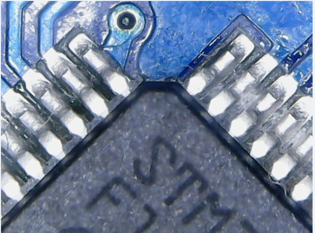
- stm32.JPG (67.01 KiB) Viewed 1033 times
PS: I purchased the cheapest usb microscope ($11) available and it works great for such shorts control..
srp
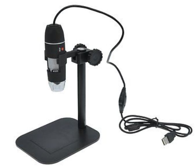
- usbmicro.JPG (30.75 KiB) Viewed 600 times
To hold the stuff in one hand and to keep it focused requires a long time training, indeed
So the mount is needed, sure.
PS: to shot the above picture require to have the microscope’s bottom hovering about 1cm over the pcb – so watching while soldering would not be easy with that stuff.
It has only 640×480.
There is not any zoom, it moves only the plate with LED and CMOS sensor to get focus, you can see it easily removing the transparent cover that seems a weak lens. My scope works better without the plastic lens but the focus distance change a lot.
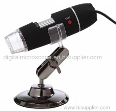
which brand and model number?
Pito wrote:Always buy 2-3 from these cheapo bards..
You may try to look at the track shorts on the pcb with a strong LED flashlight lamp. Just Xray the pcb from bottom why watching from top via magnifying glass.
Do not watch directly into the lamp via magnifying glass ![]() , however.
, however.
PS: I purchased the cheapest usb microscope ($11) available and it works great for such shorts control..
stm32.JPG
There are tons of the same type, with different mounts, from $10 up.
