I got this code from another post on this forum. Im having trouble make it work. I dont know which pin to use. I use Uart pin PA2 & PA3, PA6 (miso1) & PA7(mosi1), PA14 (miso1) & PA15(mosi1) and i can’t get it to working. i will like to use 2 Usart port to control each motor with 1 Usart port its 2 motors in total. I got it working on arduino pro mini but pro mini only have 1 usart port and i get problem when using 2 pro mini on ic2 to control each motor. im using the mini STM32. thank you for any help
i want to do the hoverboard hack.
http://drewspewsmuse.blogspot.co.uk/201 … ooter.html
#include <libmaple/usart.h>

#include "HardwareSerial.h"

void setup() {

// put your setup code here, to run once:

Serial.begin(115200);

Serial1.begin(26300);

Serial2.begin(26300);

USART1->regs->CR1 |=  USART_CR1_M_9N1 ;

USART2->regs->CR1 |=  USART_CR1_M_9N1 ;

GPIOA->regs->BSRR = 1;

}
char c = ' ';
signed int sp = 0;
void loop() {
Serial.println(c);
if (c == ' ') {
sp = 0;
} else if (c == 'q') {
sp -= 10;
} else if (c == 'w') {
sp += 10;
} else if (c == '2') {
sp += 100;
} else if (c == '1') {
sp -= 100;
}
Serial.print("speed ");
Serial.println(sp);
Serial.print(" low byte ");
Serial.print((sp & 0xFF), HEX);
Serial.print(" high byte ");
Serial.println((sp >> 8) & 0xFF, HEX);
do {
Serial1.write(256);
Serial1.write(sp & 0xFF);
Serial1.write((sp >> 8) & 0xFF);
Serial1.write(sp & 0xFF);
Serial1.write((sp >> 8) & 0xFF);
Serial1.write(85);
delayMicroseconds(300);
} while (!Serial.available());
c = Serial.read();
}
You mentioned 3 sets of pins, and also used the SPI terms mosi and miso
Are you using UARTS and SPI?
Assuming you are using the bootloader, Serial is USB-Serial.
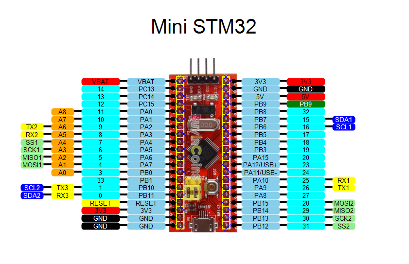
Serial1 is UART1 on PA9 and PA10
Serial2 is on UART2 ( Im not sure but this could be PA2 and PA3 – but you should double check)
If you need serial on other pins, all of the UARTs can be remapped to Alternative pins, but its not totally flexible. its just a choice of 2 sets of pins for each UART
i tested all 3 set of pins to see if i get it to work and i didnt get no responds. this is the code i used on pro mini and it uses the spi pins. do i have to use the spi pins in mini STM32? im using PA9 & PA10 for USB
#include <SoftwareSerial9.h>
#define MOSI 11
#define MISO 12
#define TX MOSI
#define RX MISO
#define LEDPIN 13
SoftwareSerial9 mySerial(RX,TX);
void setup() {
mySerial.begin(26315);
Serial.begin(115200);
}
char c = ' ';
signed int sp=0;
void loop() {
Serial.println(c);
if(c == ' ') {
sp=0;
} else if(c == '-') {
sp -= 10;
} else if(c == '+') {
sp += 10;
} else if(c == '2') {
sp += 100;
} else if(c == '1') {
sp -= 100;
}
Serial.print("speed ");
Serial.println(sp);
Serial.print(" low byte ");
Serial.print((sp & 0xFF), HEX);
Serial.print(" high byte ");
Serial.println((sp >> 8) & 0xFF, HEX);
do {
mySerial.write9(256);
mySerial.write9(sp & 0xFF);
mySerial.write9((sp >> 8) & 0xFF);
mySerial.write9(sp & 0xFF);
mySerial.write9((sp >> 8) & 0xFF);
mySerial.write9(85);
delayMicroseconds(300);
} while(!Serial.available());
c=Serial.read();
}
Precisely which board are you using (link please)
Do know if you are using the bootloader and USB Serial ?
yes im using the bootloader and USB serial.
So.. What do you have connected to what (STM32 <–> Hover board)
BTW.
I’m not entirely sure why you are using software serial, as there are 3 hardware serial channels available
I connected PA2 & PA3 to hoverboard.
this the code
#include <libmaple/usart.h>

#include <libmaple/gpio.h>

#include "HardwareSerial.h"
void setup() {
// put your setup code here, to run once:
Serial.begin(115200);
Serial1.begin(26300);
Serial2.begin(26300);
//Serial3.begin(26300);
USART1->regs->CR1 |= USART_CR1_M_9N1 ;
USART2->regs->CR1 |= USART_CR1_M_9N1 ;
USART3->regs->CR1 |= USART_CR1_M_9N1 ;
GPIOA->regs->BSRR = 1;
}
char c = ' ';
signed int sp = 0;
void loop() {
Serial.println(c);
if (c == ' ') {
sp = 0;
} else if (c == 'q') {
sp -= 10;
} else if (c == 'w') {
sp += 10;
} else if (c == '2') {
sp += 100;
} else if (c == '1') {
sp -= 100;
}
Serial.print("speed ");
Serial.println(sp);
Serial.print(" low byte ");
Serial.print((sp & 0xFF), HEX);
Serial.print(" high byte ");
Serial.println((sp >> 8) & 0xFF, HEX);
do {
Serial1.write(256);
Serial1.write(sp & 0xFF);
Serial1.write((sp >> 8) & 0xFF);
Serial1.write(sp & 0xFF);
Serial1.write((sp >> 8) & 0xFF);
Serial1.write(85);
//
Serial2.write(256);
Serial2.write(sp & 0xFF);
Serial2.write((sp >> 8) & 0xFF);
Serial2.write(sp & 0xFF);
Serial2.write((sp >> 8) & 0xFF);
Serial2.write(85);
delayMicroseconds(300);
} while (!Serial.available());
c = Serial.read();
}
I suggest you hook up a logic analyser to those pins and check the data being sent is what is required.
Serial1.begin(26300, SERIAL_9N1);
steve this is the right way to simplify the code?
#include <libmaple/usart.h>

#include <libmaple/gpio.h>

#include "HardwareSerial.h"

//

//disableDebugPorts();

//enableDebugPorts();
void setup() {
// put your setup code here, to run once:
Serial.begin(115200);
Serial1.begin(26300, SERIAL_9N1);
Serial2.begin(26300, SERIAL_9N1);
}
char c = ' ';
signed int sp = 0;
void loop() {
Serial.println(c);
if (c == ' ') {
sp = 0;
} else if (c == 'q') {
sp -= 10;
} else if (c == 'w') {
sp += 10;
} else if (c == '2') {
sp += 100;
} else if (c == '1') {
sp -= 100;
}
Serial.print("speed ");
Serial.println(sp);
Serial.print(" low byte ");
Serial.print((sp & 0xFF), HEX);
Serial.print(" high byte ");
Serial.println((sp >> 8) & 0xFF, HEX);
do {
Serial1.write(256);
Serial1.write(sp & 0xFF);
Serial1.write((sp >> 8) & 0xFF);
Serial1.write(sp & 0xFF);
Serial1.write((sp >> 8) & 0xFF);
Serial1.write(85);
//
Serial2.write(256);
Serial2.write(sp & 0xFF);
Serial2.write((sp >> 8) & 0xFF);
Serial2.write(sp & 0xFF);
Serial2.write((sp >> 8) & 0xFF);
Serial2.write(85);
delayMicroseconds(300);
} while (!Serial.available());
c = Serial.read();
}
But I think you have an unexpected behavior when you write
Serial1.write(256);
In the longer term, if you are interested in doing other microcontroller projects, It would be worth spending $10 on one of those USB logic analysers that can be found on eBay and AliExpress etc.
e.g something like this
http://www.ebay.com.au/itm/USB-24MHz-8C … Sw3YJZOjoW
Or if you have more money to spend, you can get a 16 Channel ( and more importantly, 100Mhz) usb logic analyser for around $50.
I also have a digital storage scope (100MHz) which has a 16 channel logic analyser, but I now never use the logic analyser part of the scope as the USB analysers are much better as they are much easier to use.
I connect a serial adaptor to RX & TX pin and the Serial.begin(115200) working and respond when i Println but the Serial1.begin(26300) or Serial2.begin(26300) is not respond or working
I connect a serial adaptor to RX & TX pin and the Serial.begin(115200) working and respond when i Println but the Serial1.begin(26300) or Serial2.begin(26300) is not respond or working