The Square Inch Project contest on Hackday.io made me focused on this project which I have been thinking on for a while (previously shared my opinions under an old topic).
I decided to enter the contest with a STM32duino compatible boards kit. It will be including one core board with many features. I am also planning to build some shields compatible with the core board. You must have seen such tiny board kits.
I had previously designed Arduino compatible tiny boards kit named Pointduino. The details are on my webpage if you are interested in: http://www.furkancetin.com/pointduino-boards.html
Pointduino v2.0 is about to come soon!
I will share new designs, photos and other stuffs related.
Hope you’ll like it
Furkan
Again, a nice project, where do let produce your PCB’s? (I see you did a panelizing pcb job and not every (cheap chinese) provider accept it)
I have seen previously Microduino set however I just saw the latest core board on which STM32F103 is used
I’ll STILL continue to design my board with RTC and LiPo charging and monitoring stuff on it and make it open source. I think it will be also a little cheaper. It will be definitely compatible with stm32duino.
They’re using a resonator on the micro board?? Little low budget, huh?
I have been working on PCB designs of new Pointduino, Mentol the smart watch and some other boards.
It’s a long process with continuous updates on design. I will share when they are ready to publish.
They’re using a resonator on the micro board?? Little low budget, huh?
Yes, but…!! For STM32 Core of Microduino, I have reached the image below. It has no 8mhz crystal or similar! It only includes a 32.768k resonator for RTC obviously! As far as I know, they use a clone of Maple Mini bootloader. Do they use internal oscillator or what? Can anyone explain?

i.e as far as I know, people are using the libmaple core with this board, and only supports boards with external oscillators.
So they must have a crystal somewhere.
Anyway, microduino team know what they are doing. I appreciate their work. Absolutely the best(I think) board set with a number of extension boards. So I assume, Stm works well with those compact resonators (that was an issue we talked here last month) I will definitely use 8mhz one on my compact boards.
https://www.microduino.cc/module/view?i … 00004fb0c3
perpetual back-order, suggesting they are in no rush to build more.
For $20, one can get the Particle.io Photon board which is WiFi + a substantial ARM processor and a good IDE. (I have one).
Let me tell you what I think about their being-in-no-rush; Creating a core board with STM32 chip is a great idea but they are probably thinking about problems with bootloader. MiniMaple bootloader (and our stm32duino) has issue of pressing reset button, drivers and not-recognised-error… etc. It’s not so straight forward to upload code for beginners.
Photon is revolutionary useful and compact. On the other side, boards of Microduino allows you to build prototypes faster and progress on coding quickly if you are using many peripheral modules.
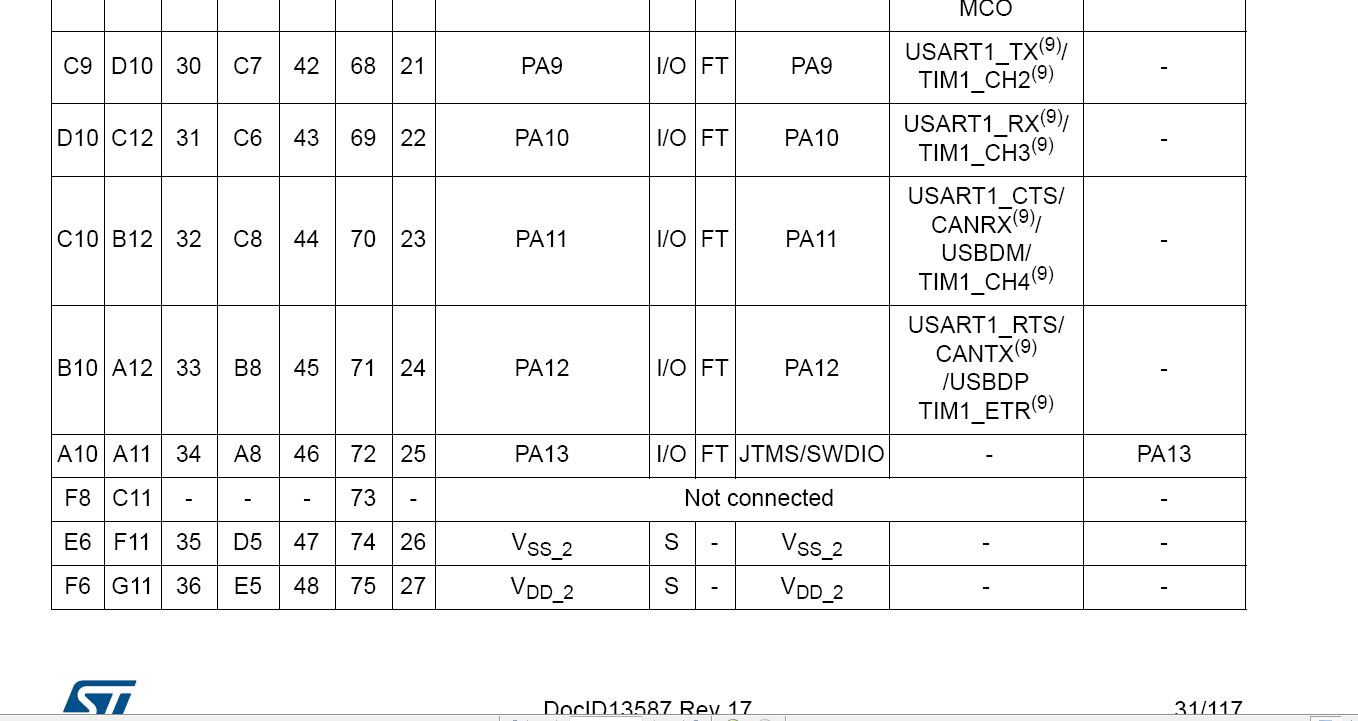
There must be four of them at least between VDD and VSS pins, right? Or they are not essential for minimal system?
Also we see too many resistors around. Two must be for BOOT1 and BOOT2, two for USB, one for LED, one for reset. Others?
It’s beneficial for us to analyze such development boards and see different hardware layouts.

of the facing side
stephen
One of the resistors is named R19 but I can see only 10 resistors.
One of the resistors is named R19 but I can see only 10 resistors.
Thats good point @zoomx. But then, why using at least 19 resistors? ![]() My bluepill has 8 resistors(2 for usb, 2 for BOOTpins, 2 for LEDs, other 2 for reset and SWD I think) and 13 caps. Ok If they are taking Maple Mini as a source and convert it, even MapleMini doesn’t have this much resistors.
My bluepill has 8 resistors(2 for usb, 2 for BOOTpins, 2 for LEDs, other 2 for reset and SWD I think) and 13 caps. Ok If they are taking Maple Mini as a source and convert it, even MapleMini doesn’t have this much resistors.
I am also curious about the mini black chip with 6 legs on Microduino STM Core. Anyone knows it or I am the only noob here?
I really appreciate open source projects!
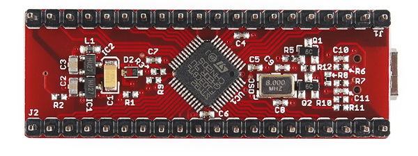
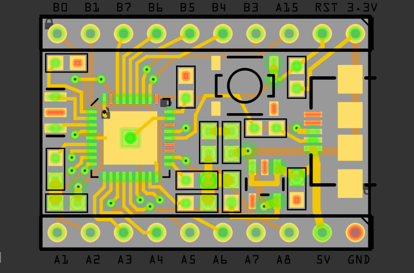
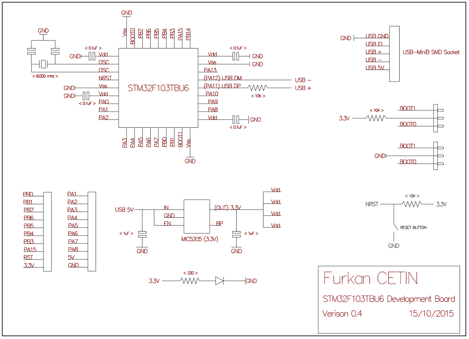
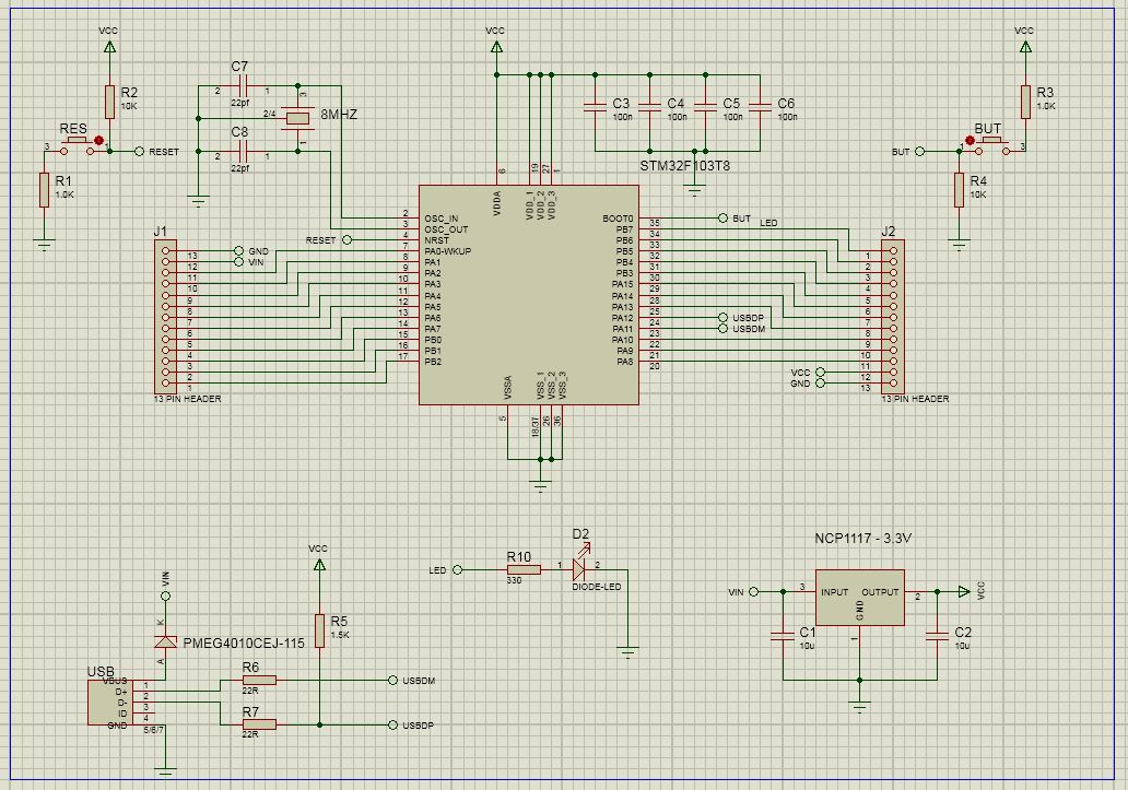
Here is fresh news from my new development board. I post here the current PCB view and the schematics. They are not the final versions!
I appreciate your comments and suggestions. This is my first STM32 based board experience. I am not sure about the USB connection, can anyone confirm whether is it correct or not? By the way, for BOOT pins, I have soldering pads on the back side of the pcb to configure as HIGH or LOW.
(Sorry for huge images. No options to put as thumbnail)
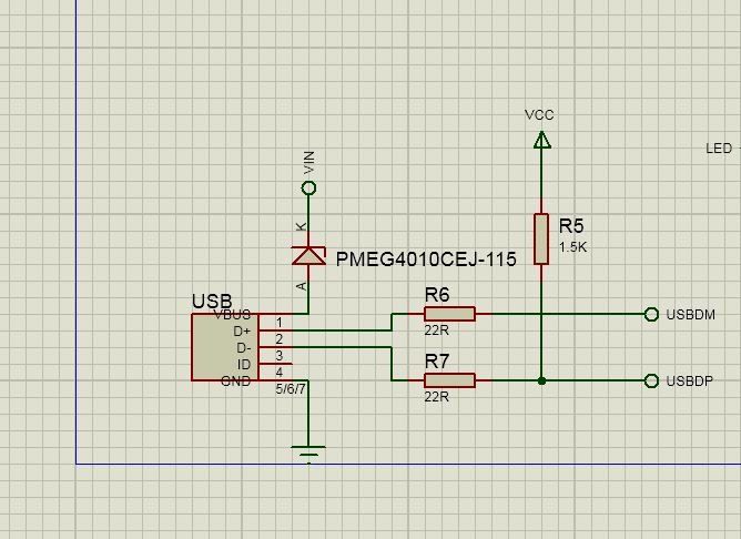
Normally I see 22 ohms in series with both usb lines
Also if you want the generic bootloader to work, you will need to pull up the appropriate USB line using a 1.5k resistor.
My boards should be here very soon. ![]()
EDIT:Here’s my completed schematic for the development board. I’m only using this for prototyping for my next project, but it’s been fun learning about the STM32f1xx so far.
Normally I see 22 ohms in series with both usb lines
Also if you want the generic bootloader to work, you will need to pull up the appropriate USB line using a 1.5k resistor.
I tried to do USB connections by analyzing my bluepill by a multimeter. I traced the connections and found such way. One of the line is directly connected to usb socket(It turned out to be PA12 pin). However, you are probably right about 1.5k resistor to pull-up. I will check everything on this weekend.
Thanks everyone for suggestions…
Furkan
I thought someone had posted a link to the BluePill schematic in another thread, but unfortunately I can remember where.
But there are plenty of other generic STM32 schematics online, so it may be worth looking at one or two of them to inform your design
I thought someone had posted a link to the BluePill schematic in another thread, but unfortunately I can remember where.
But there are plenty of other generic STM32 schematics online, so it may be worth looking at one or two of them to inform your design
I should probably put them all in a dedicated repo, and link via a wiki on that repo
How did I missed it? That’s a shiny piece of work to save in wiki and repo.
I will work on an update for my boards soon.
…
That info is also in the data sheet. Don’t forget about those data lines being switched.
EDIT:Not noticing something right away is OK to me. Noticing it after I send the design off to the fab house is when it’s a bit frustrating.
DirtyPCBs let you upload revised files while your board is still waiting to be manufactured, which can be handy.
I had to do this on one board I designed, as i forgot some clamping/limiting zener diodes on one board and had to reupload.
However as I was in a rush, I didn’t realise that I had removed a track while adding the 2 new diodes.
So when the boards arrived, there was no connections to the MCU from one of the main inputs ![]()
Fortunately I only got 10 boards made, and the missing track was from through hole to through hole, so i was able to put a strap ( small wire) on the back of the 10 PCBs
Cutting and Strapping is not unheard of, on production boards… at least for Version 1 boards.
I have taken apart VCRs etc which have obvious additional wires on them, and when I worked for a company that manufacturer electronics, there was a dedicated section in the factor to perform these changes.
However perhaps with better CAD etc nowadays, and the ease of changing designs and putting fixes into later batches, it much less likely to see this in most consumer Electonics in mass production.
DirtyPCBs let you upload revised files while your board is still waiting to be manufactured, which can be handy.
A little warning! The backside silk mask is mirrored in the dirtypcb preview but normal on the PCB itself. (I got confused about that the first time I ordered there)
On PCB production, there is no local producer here (for small amount of production), so I use Seeedstudio, Itead Studio or Elecfreaks. Therefore, I should have finished all of my board designs to make it more efficient. ![]() Anyway, working on them.
Anyway, working on them.
For bluepill, we have an issue. My bluepill has direct connection (without any component) between PA12 and USBDP + . Could you check yours please? I think I should verify the schematics and the board connections one by one.
My schematics had a small problem of swapping PA12 and PA11, I noticed, thanks. I will update it.
I built 3 of my boards that are very similar to what you’re working on. I can confirm 100% that the schematic I posted is good. Just run a 22r resistor in series with USB_DM and USB_DP and pullup USB_DP with a 1.5k resistor to 3.3v(VCC).
Furkan
Updates:
– PA11 and PA12 are swapped to correctly connect with USB lines. (Thanks to STM32Noob)
– 22R resistors are addded for both PA11 and PA12 serially. (Thanks to RogerClark, MarkM, ahull)
– 1.5K resistor is added to pull-up USB DP line (Thanks to RogerClark, MarkM, ahull)
– Pad is added to deactivate power led for power saving applications. (Thanks to ahull)
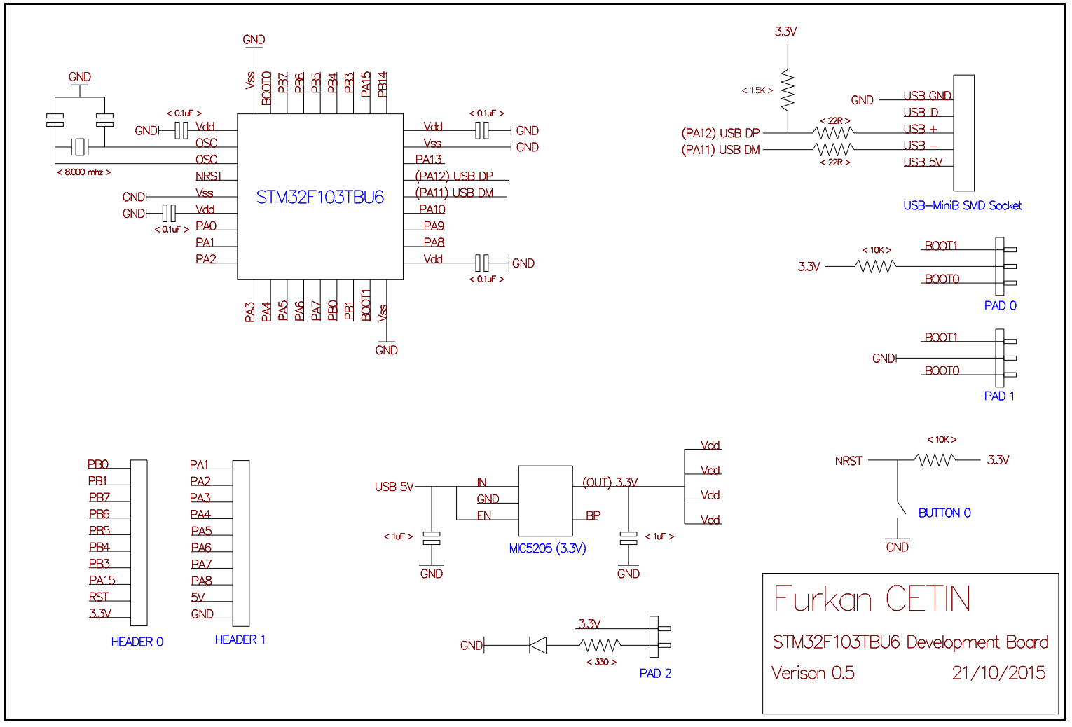
even if you’re not planning to use the adc, would it not be better to use the low noise circuit from the mic5205 data sheet?
as it’s a development board it’s about capabilities and the adc might be used at some point, it seems to be a false economy not to add an extra cap and a change of value for a second.
stephen