I did a quick search on this forum but I didn’t find any simple DAC example. So, I created two
The DAC examples are not compatible with the Arduino due DAC library but I think is the first step for us to make them have the same syntax as Arduino Due has.
Any comment is appreciated.
[Example 1] Sawtooth waveform on both DAC channels
/**

*  Example of using  the two DAC channels of the STM32F103VET micro-controller.

*  The STM32F103VET creates a Sawtooth waveform on pin PA4 (DAC Channel 1) and PA5 (DAC Channel 2)

*

*  (c) 17 August 2015 by Vassilis Serasidis

*

*/
#include "libmaple/dac.h"
int i;
void setup() {
dac_init(DAC, DAC_CH1 | DAC_CH2); // Enable both DAC channels (Channel 1 and Channel 2).
pinMode(PA4, OUTPUT); // DAC_CH1 shares the same pin with SPI1_NSS pin (PA4). So it has to be initialized again, as output.
}
void loop() {
//Create a sawtooth waveform on pins PA4 (DAC Channel 1) and PA5 (DAC Channel 2)
for(i=0;i<4096;i++){
dac_write_channel(DAC, DAC_CH1, i); //DAC, Channel, value
dac_write_channel(DAC, DAC_CH2, i); //DAC, Channel, value
}
}
The only issue I spotted is that you have used…
#include "libmaple\dac.h"
@Andy I did your backslash recommendation.
Vassilis: You don’t have any clue how to port a working I2S code to our STM32F103xxx boards (like the RCT6 or VET6)?
Vassilis: You don’t have any clue how to port a working I2S code to our STM32F103xxx boards (like the RCT6 or VET6)?
internal I2S feature of the VET6 mcu’s
Interesting thing, didn’t heard about such a feature
I will try the VET6 internal (hardware) I2S tomorrow.
I mean F103 devices with the hardware I2S as an build in option. (I first thought, that the VET6 has I2S DAC’s onboard…)
So in particular boards like the VET6, RCT6 and so on (I assume that all boards with the 12bit-2-channel-DAC’s also have the I2S possibility)
The problem is, that only in the spi.h (lower caps!) file/s there are some register entries for I2S but no functions in spi.c or further details. I think leaflabs planned it, but never realized it so the last “real maple” (with RET6) wasn’t supported even by leaflabs themselves .
A starting point could be https://github.com/mubase/STM32F4-Ardui … m32f4codec
But the files are different from the STMF1 ones and maybe (or sure) outdated.
An important point should be to enable an interrupt if the TX buffer (maybe also RX, but i dont need that) is empty, this is a little bit different to “normal” SPI
Ok, I tried to combine all the stuff mubase made for the F4 https://github.com/mubase/STM32F4-Arduino-core
Result: I give up (not even a blink sketch runs anymore after doing changes in rcc.h/c, spi.h/c). Spend more than 8 hours fooling around. It’s totally to high to me to implement I2S from level zero into this API. Here I really miss my PIC32MX: I got I2S on those MCU’s running only with the help of the datasheet….
BTW there are too much files with same or – nearly the same – names and too much crossings like rcc.h, rcc_f1.h, rcc_private.h and so on. This makes it too much difficult to reverse engineer anything. Example: There are 4 files with the name “spi.h” (ok, one is SPI.h as the library wrapper) with different behaviors.
(Sorry for my bad mood, I’m suffering from a bad illness for about one week that I got in my holidays…)
Sorry to hear you are ill ![]()
Perhaps we need to start to push to get @Sheepdoll’s core fully operational.
( That core may also helo with the GD32 boards, but I don’t think GD use HAL, I think they just use CMSIS etc)
I may have some time at the weekend to look at the sheepdoll core.
cubemx, hal, cmsis: Am I right, that it would be really easier for all of us switching between the lines (F1-F7) and porting code? So it would be a lot of work the next months/weeks but much less work in the coming future.
<…>
cubemx, hal, cmsis: Am I right, that it would be really easier for all of us switching between the lines (F1-F7) and porting code? So it would be a lot of work the next months/weeks but much less work in the coming future.
I will publish it soon
EDIT: Did you really mean STM32F103C8? This MCU has no hardware I2S implemented.
About the 6bit: are you sure you own the “standard I2S” TDA1543? There are many faulty ones on aliexpress or ebay. So sometimes they sold the TDA1543A – these only understood the “japanese audio format”. Mines are totally faulty: Only 8bit possible…
This is the reason I completely switched to the PT8211 DAC’s. Easy to setup with nearly less additional hardware and totally cheap. Best of all: they only use 3 pins: BCK,WS, DIN so no master clock is needed.
Edit: Do you own one of those saleae logic analyzer clones? In the software the I2S protocol is implemented. Helped me a lot on PIC32
>>Do you own an I2S capable device?
No, I don’t
>>Do you own one of those saleae logic analyzer clones?
Yes I have one
>>Do you own an I2S capable device?
No, I don’t
Ok, I meant the MCU, but I totally forgot you have the VET board (so with hardware I2S). I would send you some PT8211’s for free if you are interesting in doing a HW I2S support
Honestly: The missing of HW I2S implementation is the last part of the puzzle that I lack to build up a complete synthesizer (with at least 4 independent outputs/voices) with the STM32… but building a core library on my own is beyond my knowledges.
Screenshots are included.
http://www.stm32duino.com/viewtopic.php?f=18&t=519
Please help, why does the ADC on STM32F103VCT6 work properly, and on STM32F100 (STM32VLDISCOVERY) does not work ??
In the board manager, I select the required microcontroller.
code pieces like that are helpful in testing a concept but not that useful in real life, as the loop timing is generally not consistent from run to run.
a much better approach is DDS:
1) create waveform in tables;
2) index the tables via a phase accumulator;
3) in a timer isr, increase the phase accumulator and then output the waveform;
by changing the increments to phase accumulator, or the waveform tables, you can change the output frequency, or output waveform, easily.
DDS chips are essentially that, but implemented via hardware.
I think the setup would be similar to what @stsvstrong has written to use DMA to read from an 8 bit parallel GPIO device ( the OV7670 camera).
You would just need to change the direction of the DMA and the port address
I’ve been trying to make a blue pill works with a TDA1543, using the code from vassilis (viewtopic.php?f=18&t=519)
I’m wiring it in conjunction with a NE5532 , as the image below suggests:
Well, I got nothing but noise on the TDA1543 outputs. Looking the output on PA5 (clock) on oscilloscope, I got this:
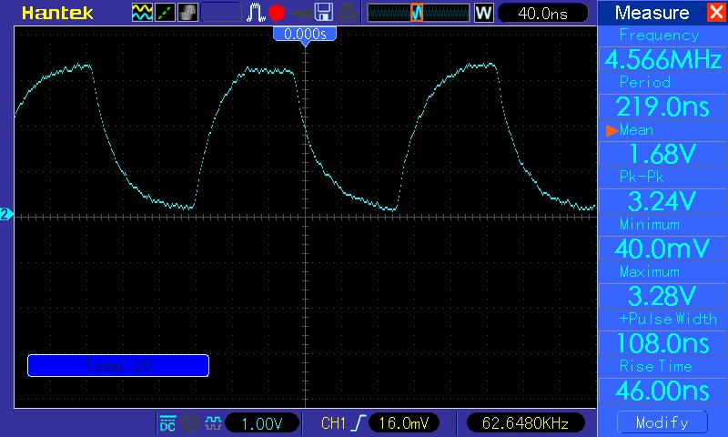
- pic_18_1.jpg (100.7 KiB) Viewed 1382 times
[escarneiro – Fri Oct 20, 2017 1:11 am] –
I’ve been trying to make a blue pill works with a TDA1543, using the code from vassilis (viewtopic.php?f=18&t=519)
I cannot find any specific code under the given link.
What is the scope of the presented circuit and how should it work?
What kind of signals are input to BCK, WS and DATA? Do you have any scope plots for those?
[stevestrong – Fri Oct 20, 2017 9:41 am] –
I cannot find any specific code under the given link.What is the scope of the presented circuit and how should it work?
What kind of signals are input to BCK, WS and DATA? Do you have any scope plots for those?
Well, this is the code. https://pastebin.com/tSBUc42b
And that plot I’ve posted is from the BCK signal. Anyway, besides of it’s strange shape, I took a look at it again and saw something even stranger (running now at half frequency / setting SPI divider at 32).
The BCK clock, alone (it is not contiguous!)
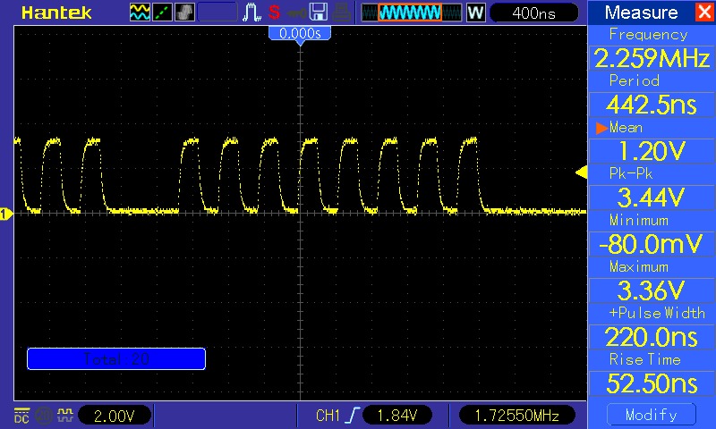
- pic_24_1.jpg (111.06 KiB) Viewed 1350 times
[ChrisMicro – Fri Oct 20, 2017 4:40 am] –
Do you really need a DAC or might be PWM or sigma delta pin toggling sufficient?
Yes, I want a DAC, but your project seems interesting too. But perhaps I couldn’t understand the scheme you made. ![]()
It would be nice to have it designed in a EDA software
1. your opamps may require +5V and -5V supplies (or higher as it is not an rail-rail opamp),
2. TDA is 5V and its input signals are 0-3.3V only,
3. the protocol is I2S, BP does not have that, afaik.
For TDA1543, you have to :
– exchange the high and low bytes order (it requires LSB then MSB, while your code is sending MSB then LSB)
– the TDA is fed with 5V, the STM32F1 is working with 3.3V – level adaptation may be necessary
EDIT
– the signal values may need adaptation, because the lowest code word -32768 = 8000h yields the largest, the highest code word 32767 = 7FFFh the smallest voltage.
(Beachte: Das niedrigste Kodewort -32768 = 8000h ergibt die größte, das höchste Kodewort 32767 = 7FFFh die kleinste Spannung)
german link: https://www-user.tu-chemnitz.de/~heha/M … DA1543.htm
[stevestrong – Sat Oct 21, 2017 9:18 am] –
The code you are using is for PT8211.
For TDA1543, you have to :
– exchange the high and low bytes order (it requires LSB then MSB, while your code is sending MSB then LSB)
– the TDA is fed with 5V, the STM32F1 is working with 3.3V – level adaptation may be necessaryEDIT
– the signal values may need adaptation, because the lowest code word -32768 = 8000h yields the largest, the highest code word 32767 = 7FFFh the smallest voltage.
(Beachte: Das niedrigste Kodewort -32768 = 8000h ergibt die größte, das höchste Kodewort 32767 = 7FFFh die kleinste Spannung)
german link: https://www-user.tu-chemnitz.de/~heha/M … DA1543.htm
Danke! Ich werde es mal gucken.
