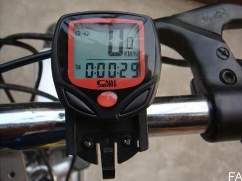
I’m thinking of building something that will do a conversion on a bicycle speedometer from km/h to miles per hour.
The device will have a reed switch or hall effect sensor input, which gets a pulse once per revolution of the bike wheel, this in turn needs to generate pulses at a ratio of 1.6 times the input pulse spacing.
The output actually needs to drive a small electromaget, as I want to build a non-invasive system rather than cutting the existing wires that go to the display (though I suppose I could do this if absolutely necessary)
This thing needs to take as little power as possible, and I could almost do it with a CMOS flip flop, if the ratio was 2 to 1, but its 1.6 to 1 so I need something with a bit of processing power.
As I have got loads of STM32 and GD32 (I’ll probably use a GD32 as I have loads of them due to a screw up in an order), so I thought I may as well use one of them
But power consumption is a problem. The GD32 boards have a 12Mhz crystal, (and the STM32 have 8Mhz), so I could change the PLL to have them run at 8mhz or 12Mhz, but thats still probably too fast for what I need to do.
I’ve looked in the STM32 Cube, but there doesnt seem to be a way to use the RTC clock as the main HSE, the slowest seems to be to use the 8Mhz HSE then the div 2 prescaler and then the times 2 multiplier to give a master clock speed of 8mhz
I suppose I may be able to use some of the low power sleep modes, but there could be an input pulse every 150ms and an output pulse every 240ms, so on average, the STM32 would need to be doing something around every 100ms.
Though I guess it doesnt need to do too much before its put back to sleep, so perhaps thats the best option, and rely on external hardware interrupt to wake it up as well as internal timers using the RTC
Though for testing its going to be far simpler just to run it on a low clock speed.
(and search the site for low power
I have done a few experiments with this, and you can get the power down to uA levels. Wake from sleep even at 72MHz, to do very little work, and then sleep again has little effect on overall power consumption, you should be able to build something that will run on a couple of AA cells for months.
but that would take all the fun out of the project :p
Re: just change the wheel size etc
The speedo doesn’t have an option to change wheel size to be large enough, The wheel size is already 700c and it doesn’t allow any larger sizes to be selected ![]()
Re: adding extra magnets
I need to do the reverse, I need less pulses rather than more pulses.
Andy
Thanks.
I’ll take a look through that thread, as I’m sure there will be things in there I can use.
stephen (ICE Trice QNT owner)
max speed 56.2mph so far, last aerobatic 540deg roll; last & so far only crash, @18.6mph walked away with 2 bruises, a kinked fairing and a seriously bent trike.
I’m thinking of building something that will do a conversion on a bicycle speedometer from km/h to miles per hour.
The device will have a reed switch or hall effect sensor input, which gets a pulse once per revolution of the bike wheel, this in turn needs to generate pulses at a ratio of 1.6 times the input pulse spacing.
<…>
As I have got loads of STM32 and GD32 (I’ll probably use a GD32 as I have loads of them due to a screw up in an order), so I thought I may as well use one of them
But power consumption is a problem. <…>
Re: adding extra magnets
I need to do the reverse, I need less pulses rather than more pulses.
Re: adding extra magnets
I need to do the reverse, I need less pulses rather than more pulses.
This looks OK for the money…
http://www.ebay.co.uk/itm/Cycling-Bike- … SwXeJXe1ZU
If you can stand the slow boat wait and the risk that it is not as described… however you don’t get the fun of hacking your own. ![]()
A few $$$ more gets you bluetooth..
http://www.ebay.co.uk/itm/Oregon-Scient … SwstxVfADE
.. or you could roll your own completely of course.
Thats a clever idea, to use 5 magnets, but I would need to find another 4 spoke magnets, and It would still need a chip to do the division and also something else to do the pulse generation. Without perhaps a 555 to generate the dummy pulse the electomagnet would be powered for 1/5 wheel rotation, rather than perhaps 1ms, so the battery consumption would be a lot higher.
Andy
Thanks. Yes, using a different speedo is definitely an option.
But I will PM you why I’m still interested in doing this ![]()
probably a long, long time ago
stephen
I still prefer to use a MCU and as I have lots of STM32’s kicking around they are a zero additional cost option. I suspect the MCU is not going to be the thing that draws the most power, its likely to be the electromagnet that takes most of the power, unless I built some fancy inductive power recovery system.
I had a few ideas of what to use for the electromagnet.
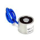
I have ordered a small electromagnet from ebay
But I also considered using one of these current detection transformers
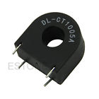
Though I think the field direction of the current transformer may be the wrong way to be useful.
I have a larger current transformer which I salved ages ago from a PCB, but it doesnt seem to produce much magnetic flux at all.
Which is why I think the small electromagnet may be the best bet, Its rated at 12V 250mA, but I was hoping that is I ran it from a 3.7V Lipo, That would would take 77mA in steady state, but much lower if I just give it a short pulse, because of the inductance of the coil.
I was intending to drive it via a small transistor, but I suspect that if I kept the pulse suitably small, I could limit the current to the amount I can get from a single GPIO pin, as I suspect the amount of current I’d need to fool the existing sensor is very low.
Edit
Just so as I can test some things today, I’ve pulled a 5V relay apart ![]()
Thanks guys
Re: just change the wheel size etc
The speedo doesn’t have an option to change wheel size to be large enough, The wheel size is already 700c and it doesn’t allow any larger sizes to be selected ![]()
Re: adding extra magnets
I need to do the reverse, I need less pulses rather than more pulses.
Why couldn’t you combine the two ideas above?
I.e. add just one second magnet, which would make your 28″/700C look like 14″ wheel, and then increase increase the wheel diameter in the speedometer to something like 1.6*14″ =22.4″ – hoping that the device gives you a choice somewhere in that neighborhood…
Unfortunately, the speedo does not allow for much variation of wheel size, I think it only allows for variation of tyre thickness.
The reason is because the speedo comes with the bike as part of a package.
Yes. I know its cheaper to just buy a new speedo, but where is the fun in that ![]()
Yes. I know its cheaper to just buy a new speedo, but where is the fun in that
The bobbin of my 5V relay was unable to do it, until I ran the 5V relay from 7V
The good news is that I only need to turn the bobbin on for 2 milliseconds, so the duty cycle on the bobbin is very low, and will be an average current drain of less than 1mA.
I have considered doing inductive energy recovery, as at the moment when the bobbin ( electromagnet) is turned off again, the reverse voltage protection diode, dumps the majority of the energy that went into the electomagnet.
I think to start with, I may just try changing the PLL and bring the clock speed down to 8Mhz, and turn off all unnecessary peripherals etc, as I think I may be able to get the operating current down to 1 or 2mA.
And only sleep completely, if there is no input from the wheel sensor after 15 seconds.
This would mean that the system would not need to have a physical power switch ( but I will prooabiy still fit one.)
At this level of power consumption, it should run for hundreds of hours on a single small LiPo cell ( i am thinking of using a small quad copter battery)
So my next challenge is the power consumption.. Watch this space ![]()
I’ve been doing some tests to see how much power can be saved simply by slowing the clock rate
I’m using a GD32 as I have a lot of them, and I don’t mind too much if I accidentally break it, and the results may not directly translate to the STM32 but…
At 120Mhz main clock the GD32 takes about 39mA
At 12Mhz it takes around 11mA
(Note. I have removed the power LED and I’m feeding power into the Vdd pin from a USB to serial converter that has 3.3V output.
Its possible that the regulator is taking some power being fed voltage on its output, but I doubt it is taking much current if any at all)
I found I can get down to running the main clock at the same frequency as the external osc (HSE) by using the 2 x Prescaler and then select the minimum PLL multiplier of x 2
I’ve had to do a bit of a hack to do this because there is an enum for the PLL multipler and I can’t simply OR in the additional bit (17) being Set into the code as there is a type violation as the PLL multipler value passed into the function that sets it up is no longer an enum.
So I’ve done a small hack in my local code and defined a PLL multiplier that doesnt really exist ( RCC_PLLMUL_1 )
typedef enum rcc_pll_multiplier {

RCC_PLLMUL_1 = (0x0 << 18)+(0x1<<17),

RCC_PLLMUL_2 = (0x0 << 18),
