long received = 0;

const unsigned long buffer_size = 128;

uint8_t buffer[buffer_size];
void setup() {
Serial1.begin(9600);
}
[...] while(Serial1.available()){
buffer[received++ % buffer_size] = Serial1.read();
}
}
Have you tried two blue pills transferring data to each other?
Or between PC and BP via an USB to serial adapter?
Have you checked with a scope the incoming data? Maybe the HC module is not outputting the data as you expect.
1. Problem with this particular device (i doubt it because of behavior is the same on all three uart ports)
2. Problem with my code (I don’t see what exactly could be wrong, moreover, i’ve tried lot of different combinations)
3. Problem with HardwareSerial implementation in Arduino_STM32 library (it also doesn’t look real because I don’t see anybody else experience the same bug)
The variable “received” should sometimes be reset, where do you do it?
Please post a simple sketch which allows us to reproduce your problem.
void loop() {

[...]
if(Serial1.available()){

buffer[received++ % buffer_size] = Serial1.read();

}

}Also, serial device to device transfer can confound anyone. Years ago, I built a QBF Arduino unit to both send and receive 4800/9600 serial streams. Maybe I should update the design to use BT.
https://www.hackster.io/rayburne/the-qb … tor-ae7015
Anyway, if you have an old mini/micro AVR board around, you might build yourself a QBF.
One possibility that comes to mind is that interrupts are being disabled (or a long (relative to the serial character rate) period of time spent in an interrupt service routine) in some other section of the code for a long enough period to cause Serial to misbehave. A test would be to cut out everything except for the minimum necessary to receive the character string.
This brings up the question of how you are looking at the received data to see that is in error. That is, is it echoed back to Serial1/Bluetooth, a different port, or shown on a local display?
[RogerClark – Wed Dec 06, 2017 8:46 am] –
Voltage levels ??
HC-05 module is feeding from STM32F103’s +5V and RX/TX are connected to the 5V tollerant PA9/PA10 pins. This is what you meant? Sorry, I’m not a HW guy, i.e. these are my first steps ![]()
[stevestrong – Wed Dec 06, 2017 9:47 am] –
Beside what Roger pointed out (voltage levels), how do you interpret the received bytes? I cannot see it in your code.
The variable “received” should sometimes be reset, where do you do it?Please post a simple sketch which allows us to reproduce your problem.
I’m writing all received bytes into a buffer and then output them to ssd1306 display:
display.print("Received: ");

display.print(received);

display.println(" byte(s)");

for (int xx=0; xx<received; ++xx) {

display.print(buffer[xx]);

display.print(", ");

}
[Pito – Wed Dec 06, 2017 1:01 pm] –
\PS: Afaik the HC-05 goes into sleep when not active for 5 secs.. You have to send a char to the module in order to wake the HC-05 up.
Thank you for the tip – I didn’t know that. But I don’t think it relates to the issue, but I will definitely modify my code to avoid it.
[mrburnette – Wed Dec 06, 2017 1:24 pm] –
You can always use your PC if equipped with BT (for testing.)Also, serial device to device transfer can confound anyone. Years ago, I built a QBF Arduino unit to both send and receive 4800/9600 serial streams. Maybe I should update the design to use BT.
https://www.hackster.io/rayburne/the-qb … tor-ae7015
Anyway, if you have an old mini/micro AVR board around, you might build yourself a QBF.
Thank you, I’m sure I have to make one.
[MarkB – Wed Dec 06, 2017 1:47 pm] –
What’s going on in the rest of your code?One possibility that comes to mind is that interrupts are being disabled (or a long (relative to the serial character rate) period of time spent in an interrupt service routine) in some other section of the code for a long enough period to cause Serial to misbehave. A test would be to cut out everything except for the minimum necessary to receive the character string.
This brings up the question of how you are looking at the received data to see that is in error. That is, is it echoed back to Serial1/Bluetooth, a different port, or shown on a local display?
Actually, I’m working with minimum configuration right now, as I mention, I connected Arduino Nano to STM32 uart, which sends 10 bytes every 5 seconds and problem is still there. The only thing I have connected to stm32 is ssd1306 oled display which I’m using for debugging. Also, I’m driving WS2812B led strip, so, probably it could be the reason. I will try to make a minimal sketch for the investigation.
https://github.com/FastLED/FastLED/issues/488
This is very reasonable for driving LEDs, but it ruins everything else ![]() So, now I can drive LEDs smoothly, but I can’t receive via UART interface (and not only UART) or, if I enable interrupts, animation will not be that smooth.
So, now I can drive LEDs smoothly, but I can’t receive via UART interface (and not only UART) or, if I enable interrupts, animation will not be that smooth.
So, now I have another problem – how to receive data on stm32f103 with disabled interrupt? As I know, there are some custom implementations for arduino which don’t use interrupts, is there something like this for stm32_arduino library?
Thank you!
Are you sending IR data ?
There are 2 or 3 libs which use DMA in one form or another, you would need to use one of those or write your own
Try googling the forum for WS2812b , as you chance of finding the libs is a much as mine (apart from I have the one I wrote in my github account), and one was written my Rick Kimball, I can’t remember who wrote the 3rd one
The lib you are using is probably the one I started with and is just a slightly modified version of the Adafruit lib and breaks USB and timeing and everything else as it disables the interrupts (which you should not do)
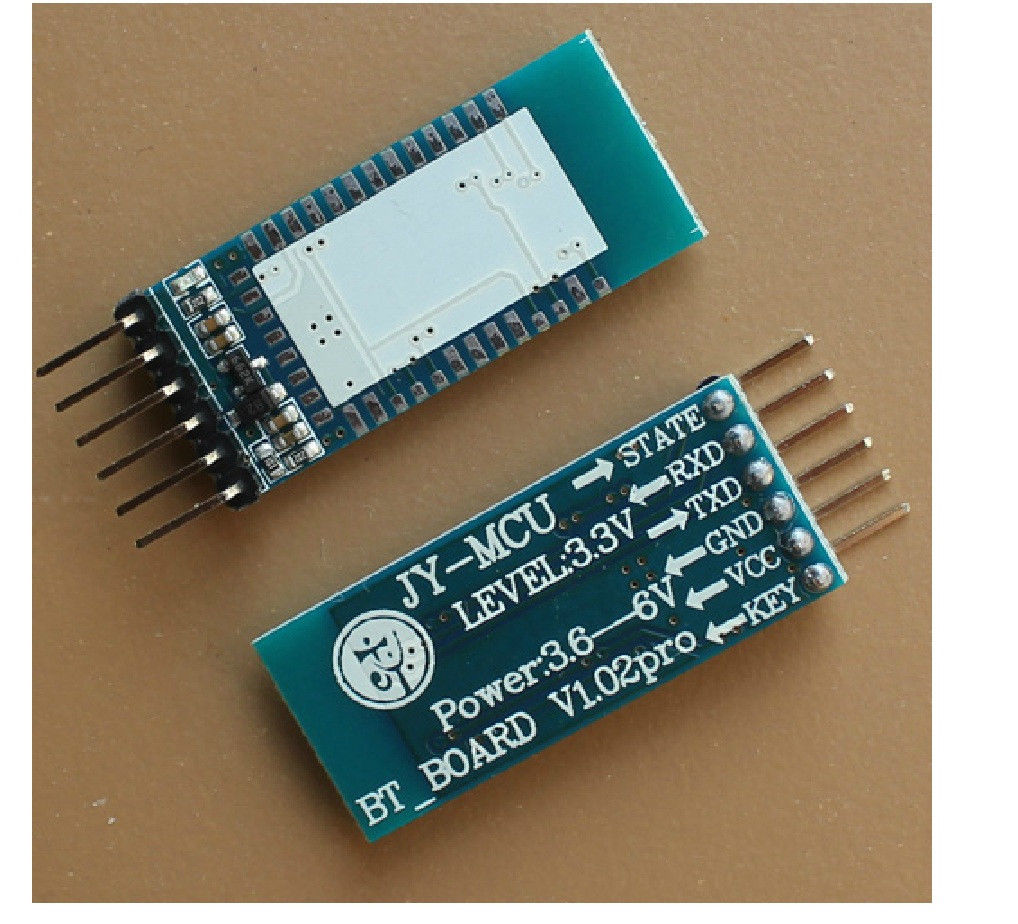
The vanilla HC-05 module is 3.3V Vcc, unless it is a module with a 5V->3.3V voltage regulator (HC-05 mounted on a breakout board).
[Pito – Fri Dec 08, 2017 12:29 am] –
HC-05 module is feeding from STM32F103’s +5V and RX/TX are connected to the 5V tollerant PA9/PA10 pins. This is what you meant? Sorry, I’m not a HW guy,
The vanilla HC-05 module is 3.3V Vcc, unless it is a module with a 5V->3.3V voltage regulator (HC-05 mounted on a breakout board).
I feed it with 5 volts, but it has voltage regulator. I have this interface board: