Now, for doing so I need to add a number of defines, and those defines are going to be different depending on the series (things like the SPI1 DMA controller and channel to use, IRQ line, same for SPI2, SPI3…SPI6).
Should I put all those defines in the SPI.h file, or rather add another .h file and include it from SPI.h?
EDIT:
I got dmaTransfer running fine in polling (blocking) mode, similar to the libmaple F1 core, at least for SPI1.
Tested with SPI1 and SPI2.
Tested by Pito with sdFat for F1 (F1 file needs modification of an #ifdef to compile for this core.)
It needs work to make it compatible with more MCUs and add non-blocking mode with callbacks.
EDIT2:
I have added defines for almost all the series, and tested compilation, but have not had the chance to test functionality except for the F4.
I have F1s, so I can test that. If anyone has L0, L1, L4 or F3 series and test it, please let me know if it works.
EDIT3:
New corrections for L0 and L4 series, which needed some extra settings.
Latest working version in this branch:
https://github.com/victorpv/STM32GENERIC/tree/SPI-DMA
- SPI no DMA rdwr speed.JPG (18.55 KiB) Viewed 1723 times
https://github.com/victorpv/STM32GENERIC/tree/SPI-DMA
Sent a PR to Daniel in case he wants to add it so more people can start testing/using it.
I tested it very basically, just sending and receiving data in the same port and comparing that I get whet I sent. So far testing only spi1. I need to find the pins for SPI2 and SPI3 and repeat the tests.
Would appreciate any feedback.
The main changes are:
Adding hdma structures for the TX and RX channels.
Enabling DMA1 and 2 peripheral clocks during .begin
A number of defines in the .h file listing what DMA Controller/Stream combination applies to each port.
If the F4 series there are multiple possible streams for each peripheral, I just picked the same the HAL MX chooses by default.
Needed:
Support for other series in the defines
In the dmaSend and Transfer functions FIFO and other settings need to be optional since they dont apply to F1 and F3 for example. Not sure of the best way to implement, I really dont like having a bunch of defines thrown in the middle of the code, so may just take the hdma settings to a separate function, and have all the conditional compiling in that single function perhaps.
Callback support. I need to add ISRs first that can manage any peripheral and figure out which one needs servicing (spi1 to 6 in some series).
Decide whether all DMA defines should be in a separate file or keep them in SPI.h
SPI no DMA rdwr speed.JPG
Double-checked the SPI clocks with LA.
PS: I think this in SPI.cpp
	if (settings.clock > apb_freq / 2) {

spiHandle.Init.BaudRatePrescaler = SPI_BAUDRATEPRESCALER_2;

} else if (settings.clock > apb_freq / 4) {

spiHandle.Init.BaudRatePrescaler = SPI_BAUDRATEPRESCALER_4;
HAL_DMA_IRQHandler() is meant to be called from IRQ handler, check cube generated stm32f4xx_it.c: `extern “C” void DMA2_Stream3_IRQHandler(void)() {HAL_DMA_IRQHandler(&hdma_spi1_tx);}` (This will also call the hdma_spi_rx->XferCpltCallback (which is set to the weak SPI_DMATransmitReceiveCplt() by HAL_SPI_TransmitReceive_DMA (which is not ideal BTW, I want custom callbacks)))
I was wondering how you tackle the requests – streams – channels for every chip problem ![]()
I only run the tests on both with a big buffer of 8KB.
8KB buffer
Speed / No DMA / DMA
21Mb / 8977.136uS / 3127.777uS
5.25Mb / 17560.336uS / 12490.117uS
EDIT: The table feature in phpBB is awful…
Used the code Pito posted in another thread for the uS measure:
	elapsed = CpuGetTicks();      // Measure the 1ms delay

spi2.dmaTransfer(array_out, array_in, 8192);

//spi2.transfer(array_out, 8192);

elapsed = CpuGetTicks()- elapsed;      // How many CPUTicks?

nanos = 5.9524 * elapsed;        // Convert to nanoseconds
FYI your code works on my F7.
I think that F2/F4/F7 is the same (stream+channel), F0/F1/F3/L1 is the same (channel), L0/L4 is the same (channel+request).
Also if the STM32 engineers were good we might get lucky, and they are always on the same (SPI1_TX is always on DMA2_Stream3 or DMA3_Stream5 on F2/F4/F7…)
Glad to know if works on the F7. I have one I got last year for free getting dust in a shelf, now can put it to some use
The theoretical DMA transfer time for an 8192 bytes large buffer at 21MHz SPI speed is 3120.762uS
Hmm, I want as a test, to replace the receive in SdFat’s SdSPiDriver.h with dmaTransfer
uint8_t receive(uint8_t* buf, size_t n) {
    SPI.dmaTransfer( buf, buf, n);

//  SPI.dmaTransfer( 0, buf, n);
// for (size_t i = 0; i < n; i++) {
// buf[i] = SPI.transfer(0XFF);
// }
return 0;
}
Is there any sense in creating a small test set for SPI and SPI DMA between SPI1 and SPI2 to verify how it works ?
SPI.dmaTransfer( buf, buf, n);
// SPI.dmaTransfer( 0, buf, n);
Yes, we need the NULL buffer
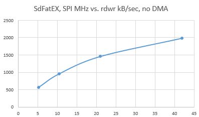
This is a F407 SDbench measurement (168MHz, BlackZE) for record – SPI1 freq vs. rdwr speed (Sammy EVO 8GB, CL10), SdFatEX, buffer size 512bytes:
- SPI vs rdwr speed.JPG (26.6 KiB) Viewed 469 times
Is there any sense in creating a small test set for SPI and SPI DMA between SPI1 and SPI2 to verify how it works ?
BTW what is the MINC=1 in
SPI.dmaSend(const_cast<uint8_t*>(buf), n, 1);
Memory Increment??
Do you need to test SDBench on F1? I can do..
BTW what is the MINC=1 in
SPI.dmaSend(const_cast<uint8_t*>(buf), n, 1);
Memory Increment??
Write latencies with SDcards are huge, 5-250ms, typically 3-50ms all the time, random occurrence..
With my above experiments I did not touch the SdFat’s SdSpiSTM32F1 driver file (even I’ve spent few hours with it..).
I simply replaced the receive and send functions (see above) in the SdSpiDriver.
That is the big Q whether we actually need the F1 driver file or not. When you set EX mode and DMA mode hardwired, then you do not need that SdSpiSTM32F1 stuff, I think.
So simply in the SpiSdDriver make from line 231+ 73+ ifdefs around the receive() and send()..
For compatibility reasons I tried to rename the SdSpiSTM32F1 to SdSpiSTM32F4, set __STM2F4__ inside (we need that flag in flags), and messed with internals, but it did not work and I elaborated that (..because the NULL pointer issue above), so I stopped and better went directly into the SdSpiDriver driver.
When there will be the SdSpiSTM32F4 with __STM32F4__ inside, it may work now. You have also to play with __STM32F4__ in the SdFatConfig.h too (maybe 2-3x). There is a lot of mess inside because of the AVR and various modi.
But there is only 1 mode which works with F1/4 – it is the EXTENDED mode with DMA.
Write latencies with SDcards are huge, 5-250ms, typically 3-50ms all the time, random occurrence..
Write latencies with SDcards are huge, 5-250ms, typically 3-50ms all the time, random occurrence..
What fat library are you using with the f411?
I did some for I2S without DMA.
The Write latencies are huge, as the Sdcard does its housekeeping (ie wearleveling, etc) almost randomly. Read latencies are minimal, about 1.5ms usually. So critical is writing – ie for 1MB/s sustained write you woud need typically ~100kB large fifo buffer (100ms outage covered). There is the “SDCard Logger with FiFO’ topic which elaborates that in detail.
Here for example:
write speed and latency

speed,max,min,avg

KB/Sec,usec,usec,usec

4381.84,16924,108,115

4508.28,8079,108,112
Starting read test, please wait.
read speed and latency

speed,max,min,avg

KB/Sec,usec,usec,usec

3816.55,2083,133,133

3819.47,1322,133,133
Is there a reason to default to that rather than the other set of pins? If there is no reason or benefit, I would suggest changing it so SWO can be used at the same time as SPI1. Not a big deal for most people, but a big annoyance for my 407 board.
I’ll just work around it then.
What fat library are you using with the f411?
What fat library are you using with the f411?
SPI\src\SPI.cpp:15:2: error: 'DMA_Stream_TypeDef' was not declared in this scope

DMA_Stream_TypeDef *_StreamTX;SPI\src\SPI.cpp:15:2: error: 'DMA_Stream_TypeDef' was not declared in this scope
DMA_Stream_TypeDef *_StreamTX;FYI your code works on my F7.
I think that F2/F4/F7 is the same (stream+channel), F0/F1/F3/L1 is the same (channel), L0/L4 is the same (channel+request).
Also if the STM32 engineers were good we might get lucky, and they are always on the same (SPI1_TX is always on DMA2_Stream3 or DMA3_Stream5 on F2/F4/F7…)
That way it will be easier to see what SPI/SDIO/I2S use, and check for conflicts.
That way it will be easier to see what SPI/SDIO/I2S use, and check for conflicts.
This is with STM32F1 (SdFatEX, DMA, 36MHz SPI) libmaple core
File size 6 MB

Buffer size 512 bytes

Starting write test, please wait.
write speed and latency

speed,max,min,avg

KB/Sec,usec,usec,usec

3533.34,25083,136,143

3594.74,15522,136,141
Starting read test, please wait.
read speed and latency

speed,max,min,avg

KB/Sec,usec,usec,usec

3257.12,1548,155,156

3258.89,1359,155,156
Done

Type any character to start
write speed and latency

speed,max,min,avg

KB/Sec,usec,usec,usec

1946.03,26753,252,261

1976.16,12442,252,257
Starting read test, please wait.
read speed and latency

speed,max,min,avg

KB/Sec,usec,usec,usec

774.14,2547,658,659

774.04,2546,658,659
Done
write speed and latency

speed,max,min,avg

KB/Sec,usec,usec,usec

1946.03,26753,252,261

1976.16,12442,252,257
Starting read test, please wait.
read speed and latency

speed,max,min,avg

KB/Sec,usec,usec,usec

774.14,2547,658,659

774.04,2546,658,659
Done
The read values above were with
buf[i] = SPI.transfer(0XFF);The read values above were with
buf[i] = SPI.transfer(0XFF);Read does not work here with F1..
With F4 it works.
http://www.stm32duino.com/viewtopic.php … 420#p27420
Read does not work here with F1..
With F4 it works.
I’ll have to wire a board to an sdcard and the jlink and see what I can find.
This is the SdBench with F1 DMA libmaple:
write speed and latency

speed,max,min,avg

KB/Sec,usec,usec,usec

1972.26,21385,251,258

1996.68,8447,251,255

1987.15,11002,251,256
Starting read test, please wait.
read speed and latency

speed,max,min,avg

KB/Sec,usec,usec,usec

2044.86,1767,248,249

2046.53,1766,248,249

2046.53,1765,248,249
write speed and latency

speed,max,min,avg

KB/Sec,usec,usec,usec

368.38,90734,1302,1365

375.24,90747,1302,1352

377.19,366597,1302,1354
Starting read test, please wait.
read speed and latency

speed,max,min,avg

KB/Sec,usec,usec,usec

error: data check
This does not have a return: `uint8_t SdSpiAltDriver::receive() {`
And change this:
SPI.transfer(const_cast<uint8_t*>(buf), n);
write speed and latency

speed,max,min,avg

KB/Sec,usec,usec,usec

781.69,22685,640,651

790.46,12851,640,645

792.59,11424,640,643
Starting read test, please wait.
read speed and latency

speed,max,min,avg

KB/Sec,usec,usec,usec

774.18,1916,658,659

774.18,1917,658,659

774.18,1917,658,659
Strange.
HAL_SPI_TransmitReceive_DMA
In all the other series, there is this comment followed by two lines which do what the comment says, but in the F1 there is the comment, but not the code to actually do it:
    /* Set the SPI Tx DMA transfer complete callback as NULL because the communication closing

is performed in DMA reception complete callback  */

hspi->hdmatx->XferHalfCpltCallback = NULL;

hspi->hdmatx->XferCpltCallback = NULL;
Tested on maple mini. Connect SPI1 pins to SPI2 (They are set as master and slave). It sends using SPI.transfer, SPI.dmaTransfer (with without NULL sendbuffer), SPI.dmaSend. Then it writes the sent and received bytes on master/slave SPI to Serial.
Observations: communication until dmaSend works fine. than it is corrupted.
If dmaSend is commented out, but dmaTransfer is used, everying works fine (almost…).
Actually implementing dma irq (with low priority!!! else spi salve gets borked up) seems to fix the problem. But then HAL_DMA_PollForTransfer does not work and you need to set custom flags.
At 36MHz SPI and SdFatEX and DMA you should get ~3.5MB/s rd/wr..
File size 5 MB

Buffer size 512 bytes

Starting write test, please wait.
write speed and latency

speed,max,min,avg

KB/Sec,usec,usec,usec

3576.31,7794,139,141

3566.11,8057,139,141

3563.56,8054,139,141
Starting read test, please wait.
read speed and latency

speed,max,min,avg

KB/Sec,usec,usec,usec

3162.35,930,159,160

3164.35,903,159,160

3162.35,903,159,160
Done
1. F1 DMA on – the bug in F1 DMA found and fixed,
2. F1 none DMA – needs debug/fix by Daniel?
3. F4 DMA is ok (?),
4. F4 none DMA – needs debug/fix by Daniel?
Is that correct?
1. F1 DMA on – the bug in F1 DMA found and fixed,
2. F1 none DMA – needs debug/fix by Daniel?
3. F4 DMA is ok (?),
4. F4 none DMA – needs debug/fix by Daniel?
Is that correct?
UPDATE:
Seems like I finally fond the problem. The DMA ch .CCR register was not taking the value because the DMA channel was still enabled.
I thought the channel was going to disabled state by itself when the transfer is completed, but it doesn’t, and as far as it’s enabled the CCR won’t take a change to the MINC bit. If I first clear the CCREN bit in the CCR, then it will take changes.Not sure if it works in the F4 because the HAL takes care of disabling the channel when DMA_Init is called, or because the peripheral takes changes even if enabled, will have to check more on that.
Every other series I checked has these 2 lines in HAL_DMA_Init to disable the channel before making changes to CCR, except the F1 HAL:
/* Disable the peripheral */

__HAL_DMA_DISABLE(hdma);C:\Users\pito\MyCode\Arduino\hardware\Arduino_STM32SerBuff\STM32DE\libraries\SPI\src\SPI.cpp:234:25: error: 'struct DMA_Stream_TypeDef' has no member named 'CCR'
hdma_spi_tx.Instance->CCR &= ~DMA_CCR_EN;C:\Users\pito\MyCode\Arduino\hardware\Arduino_STM32SerBuff\STM32DE\libraries\SPI\src\SPI.cpp:234:25: error: 'struct DMA_Stream_TypeDef' has no member named 'CCR'
hdma_spi_tx.Instance->CCR &= ~DMA_CCR_EN;I have not tried with F1 none DMA yet, I have to buy new cards tomorrow
I have not tried with F1 none DMA yet, I have to buy new cards tomorrow
At 16KB buffer libmaple seems to have a slight edge on reads, and this core seems to have it in writes, but nothing really significant.
Also flash and ram utilization is very similar, with smaller flash used in libmaple and smaller RAM used in this core.
This is all with the same class 6 sd card.
Memory usage:
libmaple:

section             size        addr

.text              28048   134217728

.ARM.exidx             8   134245776

.data               2632   536870912

.rodata             3056   134248416

.bss               18952   536873544
And you used the “standard” SdFat lib, not the SdFatEX, right? Can you also test with the EX version?
Btw, the FLASH/RAM ratio for libmaple F1/F4 could be improved if you would place the PIN_MAP into FLASH, as I did it in my black F4 branch.
I have not tried with F1 none DMA yet, I have to buy new cards tomorrow
https://www.sdcard.org/downloads/formatter_4/
instead to format them with “standard OS” formatters..
& for the adventurous it may be possible to brute force it in linux
https://forum.xda-developers.com/showth … p?t=502095
some other fun stuff about sd card, sd cards are mcus
https://www.bunniestudios.com/blog/?p=3554
The crux is that a firmware loading and update mechanism is virtually mandatory, especially for third-party controllers. End users are rarely exposed to this process, since it all happens in the factory, but this doesn’t make the mechanism any less real. In my explorations of the electronics markets in China, I’ve seen shop keepers burning firmware on cards that “expand” the capacity of the card — in other words, they load a firmware that reports the capacity of a card is much larger than the actual available storage. The fact that this is possible at the point of sale means that most likely, the update mechanism is not secured.
In our talk at 30C3, we report our findings exploring a particular microcontroller brand, namely, Appotech and its AX211 and AX215 offerings. We discover a simple “knock” sequence transmitted over manufacturer-reserved commands (namely, CMD63 followed by ‘A’,’P’,’P’,’O’) that drop the controller into a firmware loading mode. At this point, the card will accept the next 512 bytes and run it as code.
http://s2.q4cdn.com/000096926/files/doc … ENERAL.pdf
11.3. CSD REGISTER
The Card-Specific Data register provides information regarding access to the card contents.data format, error correction type, maximum data access time, whether the DSR register can be used, etc.
C_SIZE
This field is expanded to 22 bits and can indicate up to 2 T Bytes (It is the same as the maximum memory space specified by a 32-bit block address.)
This parameter is used to calculate the user data area capacity in the SD memory card (not included the protected area). The user data area capacity is calculated from C_SIZE as follows Memory capacity = (C_SIZE+1) * 512K byte. As the maximum capacity of the Physical Layer Specification Version 2.00 is 32 GB, the upper 6 bits of this field shall be set to 0.
C_SIZE seem to imply that the super secret “protected area” is a *hidden partition* i.e. not visible even through normal register hardware access.
if true we could possibly just *format* that card (with any tools) and try again, since it won’t touch that “protected area” anyway
![]()
Don’t Format SD cards with OS utilities – on arduino forum:
https://forum.arduino.cc/index.php?topic=228201.0
And you used the “standard” SdFat lib, not the SdFatEX, right? Can you also test with the EX version?
Btw, the FLASH/RAM ratio for libmaple F1/F4 could be improved if you would place the PIN_MAP into FLASH, as I did it in my black F4 branch.
You are most probably using either the “PIN_MAP_in_flash” or the “PIN_MAP_in_flash_take_2” branch.
Yeah, as you probably noticed, I am not giving up the libmaple core, my “first love” ![]()
I have already adapted the DMA channels from F1 to streams for F4, it was not very difficult, 2 hours of work.
The DMA is not yet properly working with SPI, I have to debug it. But I am confident that it will work.
Meanwhile I am optimizing the multiple (non-DMA) read routine for SPI to get a (mostly) continuous clock while reading the bytes, similar to the write routine. I had a similar try couple of month before, it was not working, but now I found a way to make it work correctly.
The WR performance of the non-DMA version, what I checked, seems to be very-very close to the DMA version of generic core @21 MHz, according to Pito’s measurements.
The most critical part is to read the Rx(n) data before Tx(n+1) is written.
And the solution is indeed to disable the interrupts between writing byte(n) and reading byte(n-1). Then interrupts can again be enabled.
The maximum reserved time is up to 8 SPI clock periods.
Here is how it looks in C code:
void SPIClass::read(uint8 *buf, uint32 len)

{

if ( len == 0 ) return;

spi_rx_reg(_currentSetting->spi_d);		// clear the RX buffer in case a byte is waiting on it.

spi_reg_map * regs = _currentSetting->spi_d->regs;

// start sequence: write byte 0

regs->DR = 0x00FF;					// write the first byte

// main loop

while ( (--len) ) {

while( !(regs->SR & SPI_SR_TXE) );	// wait for TXE flag

noInterrupts();			// go atomic level - avoid interrupts to surely get the previously received data

regs->DR = 0x00FF;		// write the next data item to be transmitted into the SPI_DR register. This clears the TXE flag.

while ( !(regs->SR & SPI_SR_RXNE) );	// wait till data is available in the DR register

*buf++ = (uint8)(regs->DR);		// read and store the received byte. This clears the RXNE flag.

interrupts();					// let systick do its job

}

// read remaining last byte

while ( !(regs->SR & SPI_SR_RXNE) );	// wait till data is available in the Rx register

*buf = (uint8)(regs->DR);			// read and store the last received byte

}You are most probably using either the “PIN_MAP_in_flash” or the “PIN_MAP_in_flash_take_2” branch.
Anyway, I added the same feature to my black F4 branch, too.
But I suspect it may not be enough like that.
What happens if an interrupt is triggered between this line
regs->DR = 0x00FF; // write the first byt
and
noInterrupts(); // go atomic level – avoid interrupts to surely get the previously received data
the ISR will get called, count 13 cycles min, first byte is completely shifted out, byte incoming goes to DR. Then ISR returns, interrupts disable, you write a new byte to DR that start shifting out quick since the previous one is completed (I think it takes 1 cycle to move from the DR fifo to the spi shift register), then you have to execute all this before it finishes shifting out that second byte:
while ( !(regs->SR & SPI_SR_RXNE) ); // wait till data is available in the DR register
*buf++ = (uint8)(regs->DR);
If those 2 lines can’t complete in under 8 cycles, we lost a byte. (but wouldn’t rather be closer to 16 cycles max since the SPI runs at 36Mhz max?).
If it’s 16 cycles, then may be enough, if I’m wrong and it’s 8, then you may need to check the generated code to make sure that doesn’t turn in too many instructions, and that may even be out of our control if people changes the optimization flags…
BTW I am talking cpu cycles, not SPI cycles.
EDIT: I see you were talking 8 spi cycles, so we are talking the same time at max speed. 8 spi or 16 cpu cycles in an F1. With that I can’t see any problem unless the compiler does something crazy with those 2 lines.
The F1 should benefit from the same changes, was your test above in F1 or F4?
In the transfer function you should be able to do the same to optimize speed, as long as we are sending more than 1 byte. did you test optimizing that one?
But here I assumed that the CPU is able to execute those couple of instructions, being that CPU clock is always a multiple of SPI clock.
I am investigating the number of needed instructions with the debugger, will come back soon to this.
But here I assumed that the CPU is able to execute those couple of instructions, being that CPU clock is always a multiple of SPI clock.
I am investigating the number of needed instructions with the debugger, will come back soon to this.
BTW the best check on SPI with Sdfat will be under FreeRtos
                     SPIClass::read(unsigned char*, unsigned int):

080068be: 0x000030b5   push    {r4, r5, lr}

336                  	if ( len == 0 ) return;

080068c0: 0x0000f2b1   cbz     r2, 0x8006900 <SPIClass::read(unsigned char*, unsigned int)+66>

337                  	spi_rx_reg(_currentSetting->spi_d);		// clear the RX buffer in case a byte is waiting on it.

080068c2: 0x0000036e   ldr     r3, [r0, #96]   ; 0x60

080068c4: 0x0000db68   ldr     r3, [r3, #12]
080068c6: 0x00001b68   ldr     r3, [r3, #0]
080068c8: 0x0000d868   ldr     r0, [r3, #12]
341                  	regs->DR = 0x00FF;						// write the first byte

080068ca: 0x0000ff20   movs    r0, #255        ; 0xff

080068cc: 0x0000d860   str     r0, [r3, #12]
080068ce: 0x00008c18   adds    r4, r1, r2

080068d0: 0x0000481c   adds    r0, r1, #1

343                  	while ( (--len) ) {

080068d2: 0x0000a042   cmp     r0, r4

080068d4: 0x00000ed0   beq.n   0x80068f4 <SPIClass::read(unsigned char*, unsigned int)+54>

344                  		while( !(regs->SR & SPI_SR_TXE) );		// wait for TXE flag

080068d6: 0x00009d68   ldr     r5, [r3, #8]
080068d8: 0x0000ad07   lsls    r5, r5, #30

080068da: 0x0000fcd5   bpl.n   0x80068d6 <SPIClass::read(unsigned char*, unsigned int)+24>

080068dc: 0x000072b6   cpsid   i

346                  		regs->DR = 0x00FF;						// write the next data item to be transmitted into the SPI_DR register. This clears the TXE flag.

080068de: 0x0000ff25   movs    r5, #255        ; 0xff

080068e0: 0x0000dd60   str     r5, [r3, #12]
347                  		while ( !(regs->SR & SPI_SR_RXNE) );	// wait till data is available in the DR register

080068e2: 0x00009d68   ldr     r5, [r3, #8]
080068e4: 0x0000ed07   lsls    r5, r5, #31

080068e6: 0x0000fcd5   bpl.n   0x80068e2 <SPIClass::read(unsigned char*, unsigned int)+36>

348                  		*buf++ = (uint8)(regs->DR);				// read and store the received byte. This clears the RXNE flag.

080068e8: 0x0000dd68   ldr     r5, [r3, #12]
080068ea: 0x00f8015c   strb.w  r5, [r0, #-1]
080068ee: 0x000062b6   cpsie   i

080068f0: 0x00000130   adds    r0, #1

080068f2: 0x0000eee7   b.n     0x80068d2 <SPIClass::read(unsigned char*, unsigned int)+20>

080068f4: 0x0000013a   subs    r2, #1

352                  	while ( !(regs->SR & SPI_SR_RXNE) );	// wait till data is available in the Rx register

080068f6: 0x00009868   ldr     r0, [r3, #8]
080068f8: 0x0000c007   lsls    r0, r0, #31

080068fa: 0x0000fcd5   bpl.n   0x80068f6 <SPIClass::read(unsigned char*, unsigned int)+56>

353                  	*buf++ = (uint8)(regs->DR);				// read and store the received byte

080068fc: 0x0000db68   ldr     r3, [r3, #12]
080068fe: 0x00008b54   strb    r3, [r1, r2]
08006900: 0x000030bd   pop     {r4, r5, pc}
i’d guess it isn’t quite possible to ‘have the cake & eat it’, but it shows meddling with bare metal isn’t easy with lots of compromises, e.g. the cpu is busy, keystrokes, usb serial nusances won’t be attended to until it is done ![]()
either way 4MB (32 mbps) per secs is excellent for SPI transfers on a single pin, multi tasking can still be achieved at a higher level by yielding say every 4k bytes so that other tasks have a chance to run, at these speeds read/write 4k bytes take a mere 1ms! ether way on f1, it would need to yield at 512 bytes due to lack of ram ![]()
it would seem to me that to work with no interrupts suppression, the protocol above this spi hardware layer would need to have some error correction mechanisms, e.g. if a byte is missed during reads due to an interrupt, a checksum need to catch that so that the master/host can request for the same packet to be re-transmitted, if that being the case it may be possible to do without masking interrupts, but won’t be easy to figure those complicated interactions out as well
i’d guess it isn’t quite possible to ‘have the cake & eat it’, but it shows meddling with bare metal isn’t easy with lots of compromises, e.g. the cpu is busy, keystrokes, usb serial nusances won’t be attended to until it is done ![]()
either way 4MB (32 mbps) per secs is excellent for SPI transfers on a single pin, multi tasking can still be achieved at a higher level by yielding say every 4k bytes so that other tasks have a chance to run, at these speeds read/write 4k bytes take a mere 1ms! ether way on f1, it would need to yield at 512 bytes due to lack of ram ![]()
Same class 6 card, with 512 buffer gets 3MB/s, and using a 16KB buffer barely improves it anymore, so it looks like that’s the limit for that card.
STM32Generic core, F103RFT mcu, 72Mhz, DMA, DIV/2, SdFatEX, 512 bytes buffer:
FreeStack: 92664

Type is FAT32

Card size: 4.08 GB (GB = 1E9 bytes)
Manufacturer ID: 0X3

OEM ID: SD

Product: SD04G

Version: 8.0

Serial number: 0X5700E101

Manufacturing date: 8/2008
File size 5 MB

Buffer size 512 bytes

Starting write test, please wait.
write speed and latency

speed,max,min,avg

KB/Sec,usec,usec,usec

3071.06,154124,141,164

3391.91,24856,141,148

3056.04,153749,141,165
Starting read test, please wait.
read speed and latency

speed,max,min,avg

KB/Sec,usec,usec,usec

3054.17,1200,165,166

3054.17,1201,165,166

3054.17,1202,165,166
Done

Type any character to start
Besides a bunch of overhead starting the transfer, the rest of the loop is exactly the same send 2 bytes, then read and send 1 by one, and read a last one.
But with 1 major difference. It doesn’t disable interrupts at any time! At least not in the F1 and F4 HALs.
I think that may explain the corruption Pito was getting when running tests without DMA. Since interrupts are enabled and ongoing for systick, usb…
EDIT
For comparison, the libmaple core SD bench on blue pill for my Sandisk ultra CL10 (red/grey) card, F103 @ 72MHz, SPI1 @ 36MHz, with DMA:
File size 5 MB

Buffer size 512 bytes

Starting write test, please wait.
write speed and latency
speed,max,min,avg
KB/Sec,usec,usec,usec
3700.73,9752,131,136
3703.47,16335,131,136
Starting read test, please wait.
read speed and latency
speed,max,min,avg
KB/Sec,usec,usec,usec
3382.73,989,149,150
3385.02,847,149,150
Here is a compilation of implementations in various cores: https://gist.github.com/danieleff/64e51 … 6ab1167ad7
(The current discussion on Arduino dev forums: https://groups.google.com/a/bcmi-labs.c … 12I7sB_Elk )
The libmaple looks just… weird?
Here is a compilation of implementations in various cores: https://gist.github.com/danieleff/64e51 … 6ab1167ad7
(The current discussion on Arduino dev forums: https://groups.google.com/a/bcmi-labs.c … 12I7sB_Elk )
The libmaple looks just… weird?
didn’t figure out there is quite a bit of SPI ‘history’ with various interfaces
I will double check with the same SPI lib (latest) with F1 now..
Blue F103ZET, new Samsung EVO 16GB CL10, 36MHz SPI speed, SdFatEX, DMA:
File size 5 MB

Buffer size 512 bytes

Starting write test, please wait.

write speed and latency

speed,max,min,avg

KB/Sec,usec,usec,usec

3431.49,16295,140,146

3472.00,8603,140,145

3438.57,20800,140,147

Starting read test, please wait.

read speed and latency

speed,max,min,avg

KB/Sec,usec,usec,usec

3176.42,1878,158,159

3180.46,1414,158,159

3180.46,1417,158,159I have several times caught it witht the debugger haging on waiting for TXE to the set, and stays at 0. I still don’t have an explanation for that. And I have seen that in the F1 only as far as I remember.
As long as the SPI peripheral is enabled, after a few cycles TXE has to become 1 when the current data is completely shifted out, but a few times that doesn’t happen. It may have to do with having the debugger connected and poking around data and registers though, not sure, but just can’t understand why would that happen.
Other than that, the 20cm wires may be just at the limit of it working or not, you get a bit more noise in the line at 42Mhz and the spi port or the sdcard miss the edges…
I have done a few cosmetic corrections, but nothing major, and just pushed those updates to my repo. I haven’t sent a new PR to Daniel until we confirm the library itself is reliable. I have to wire an sdcard socket to the F4 board and run a few tests.
I think it would be good to test the library with displays too as they will make it very apparent if something is corrupted in the screen. Probably more so that the bench test, since I think it doesn’t check every byte on reads, but only the last 2 from each block.
Anyhow, we need more testers for SPI and SDIO stuff to be involved
Here is a compilation of implementations in various cores: https://gist.github.com/danieleff/64e51 … 6ab1167ad7
(The current discussion on Arduino dev forums: https://groups.google.com/a/bcmi-labs.c … 12I7sB_Elk )
The libmaple looks just… weird?
Added an example video+audio player. Plays at 27 FPS on F407, ILI9341, SPI+I2S nonblocking DMA, SDIO blocking DMA. Example output without sound cause my crappy phone cant record sound: http://danieleff.com/stm32/test/output_no_sound.mp4
(Victor I integrated most of your changes, but DMA is now centralized, please use master for further development)
This library was modified to support DMA in Maple Mini by Victor in 2015.
Would this lib work with Generic? (Not tested yet).


