I am looking for a arduino library for the 1-channel 10bit SPI DAC AD5310
–> http://www.analog.com/media/en/technica … AD5310.pdf
currently I am using the STM32F103VET6 on a given hardware, where 2 of this DAC are connected to SPI2:
PB12 – NSS (“chip-select”)
PB13 – SCK
PB14 – MISO
PB15 – MOSI
maybe some of you did something like that in the past,
or someone knows that this kind of DAC is SW-compatible with a more common SPI DAC from e.g. TI or so …
There is really no need for a library.
Just write 16bit to SPI port (example: count from 0 to 65535), start with low clock frequencies and test out the limit.
via datasheet:
See Figure 2. 3 Maximum SCLK frequency is 30 MHz at VDD = 3.6 V to 5.5 V and 20 MHz at VDD = 2.7 V to 3.6 V.
Something like this:
SPI.beginTransaction(SPISettings(18000000, MSBFIRST, SPI_MODE0, DATA_SIZE_16BIT));you can try to rise the clock frequency (30000000)
#include <SPI.h>

#define CS PB13  // your Sync pin
void setup() {

//SPI.begin(); // not needed, done in beginTransaction() - edit by stevestrong

pinMode(CS,OUTPUT);

SPI.beginTransaction(SPISettings(18000000, MSBFIRST, SPI_MODE0, DATA_SIZE_16BIT));

}

void loop() {

for (uint16_t counter=0;counter<65535;counter++)

{

digitalWrite (CS, LOW);        // assert Slave Select

SPI.write (counter);  // do a transfer

digitalWrite (CS, HIGH);       // de-assert Slave Select

//SPI.endTransaction ();         // transaction over

}

}
I’ll try that,
but why writing a 16-bit word on a 10bit DAC ?
if you look at page 11 of 16 of the data-sheet you can read the following:
The input shift register is 16 bits wide (see Figure 25). The first
two bits are don’t cares. The next two bits are control bits that
control which mode of operation the part is in (normal mode or
one of the three power-down modes). There is a more complete
description of the various modes in the Power-Down Modes
section. The next 10 bits are the data bits. These are transferred
to the DAC register on the 16th falling edge of SCLK. Finally,
the last two bits are don’t cares.
So I think I have to do some kind of additionally bit-shifting and as well set the 2 control bits right (?)
that the 2 SPI-DACs are connected in the following way to the STM32 SPI2 (my given board):
.
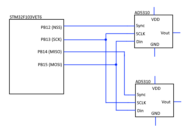
- Schema.png (10.13 KiB) Viewed 368 times
#include <SPI.h>

#define CS1 PB12  // your Sync pin of the first AD5310 DAC

#define CS2 PB14  // your Sync pin of the second AD5310 DAC
SPIClass SPI_2(2);
void setup() {
pinMode(CS1,OUTPUT);
SPI_2.beginTransaction(SPISettings(18000000, MSBFIRST, SPI_MODE0, DATA_SIZE_16BIT));
pinMode(CS2, OUTPUT); //Initiallize the MISO pin as output. This line must be after SPI initiallization.
}
void loop() {
for (uint16_t counter=0;counter<65535;counter++)
{
digitalWrite (CS1, LOW); // assert Slave Select
SPI_2.write (counter); // do a transfer
digitalWrite (CS1, HIGH); // de-assert Slave Select
digitalWrite (CS2, LOW);
SPI_2.write (65535 - counter); // do a transfer
digitalWrite (CS2, HIGH);
}
}
The board layout is very weird, using the standard SPI port and using CS(2) on the MOSI pin…. I would resolder that quirks.
For sure you can rewrite any soft_SPI library from AVR-Arduino for it and change the AVR low-level pin toggle routines for STM32 (leaflab core) ones or use the suggestion Vassilis made.
Maybe it would help us, if you can explain something more:
What kind of board is it?
What you are going to do with it? (So do you need speed in driving the DAC’s….and so on)
https://barth-elektronik.com/en/mini-plc.html
I’m right?
Matthias
[madias – Fri Mar 30, 2018 7:46 pm] –
Ok, I think you are using one of this:
https://barth-elektronik.com/en/mini-plc.html
nope …
I am using russian PLC OWEN PR-200 (Овен ПР200)
—-
since there is no need for bidirectional SPI, and no need for highest speed,
I will try a simple shiftOut() function like these:
– in the core: https://github.com/rogerclarkmelbourne/ … ft.cpp#L29
– slow: viewtopic.php?p=17090#p17090
– fast: viewtopic.php?p=17131#p17131
but I will try @Vassilis solution as well…
About the two control bits: I think you can let the first two MSB to “0” for “normal operation”
