I want to use an external DAC in Stm32f103c8.
How can I get a value of 0-255 as 8 logic output.
thax ![]()
[Pito – Mon Jan 15, 2018 1:02 pm] –
Which external DAC, give us the link..
I do not have any schematics.
For example PA0 PA1 PA2 PA3 PA4 PA5 PA6 I can get 8 outputs with for 0-255 data.
or if the outputs are different
PA0, PA1, PB2, PB5 etc.
analogWrite(pin, value); // value 0 - 255
analogWrite(PA7, 189);
or
pwmWrite(pin value); // value 0 - 65535
How can I get a value of 0-255 as 8 logic output.
generally you write a piece of code, as per the datasheet of your external DAC, to communicate with it.
that works 100% of the time with 100% of the devices, DAC or not.
There are R2R DACs, 1-2-4-8..R DACs, I2C DACs, SPI DACs, parallel DACs, PWM DACs, etc..
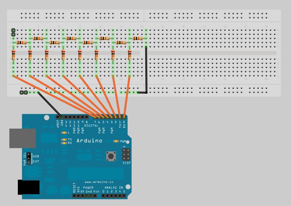
can we do it like the picture?
Yes you can do it, sure. You may wire it to a port, ie. PortA or PortB, PA0-PA7 or PB0-PB7, and then send the DAC value to the PortA or PortB in a single write.
Mind the stm32 is a 3.3Volt device, thus the R2R output will be 0..3.28V max.
PA0, PA1, PA2, PB12, PB13, PB14, PA3, etc.
There is a method
pinMode(PA0, OUTPUT);

..

pinMode(PB12, OUTPUT);

..

// write the DACvalue 0-255, 8bit

digitalWrite(PA4, (DACvalue & 0x80));  // the highest DACvalue bit7

digitalWrite(PA3, (DACvalue & 0x40));

digitalWrite(PB14, (DACvalue & 0x20));

digitalWrite(PB13, (DACvalue & 0x10));

digitalWrite(PB12, (DACvalue & 0x08));

digitalWrite(PA2, (DACvalue & 0x04));

digitalWrite(PA1, (DACvalue & 0x02));

digitalWrite(PA0, (DACvalue & 0x01));  // the lowest DACvalue bit0

..
If I were you, I would use an SPI DAC such as MCP4921 (single DAC) or MCP4922 (double DAC) that can provide 25mA output as-is ![]()
Just think about the values the DAC outputs while those pins are being set / reset.
you will need a mechanism to latch the output.
Can’t be solved by using a filtered PWM output?
I don’t know how that can be addressed via software. a latch, including a latch-equipped shift register, would be my way to go for glitch-free output. Otherwise, a capacitor can help reduce the glitches, with performance issues of its own however.
uint8_t DPINS[] = {PA0, PB0, PA1, PB0, PB12, PB13, PB14, PB15};   // random pin
void setup(){
for (uint8_t i = 0; i <= sizeof(DPINS) - 1; i++)

pinMode(DPINS[i], OUTPUT);

}
num = sine[i];  // sine table value
for (byte i=0; i<= sizeof(DPINS) - 1; i++) {

byte state = bitRead(num, i);

digitalWrite(DPINS[i], state);

}
uint8_t DPINS[] = {PA0, PB0, PA1, PB1, PB12, PB13, PB14, PB15};   // random pin

uint8_t num;
uint8_t sine[256] = {
0x80, 0x83, 0x86, 0x89, 0x8C, 0x90, 0x93, 0x96,
0x99, 0x9C, 0x9F, 0xA2, 0xA5, 0xA8, 0xAB, 0xAE,
0xB1, 0xB3, 0xB6, 0xB9, 0xBC, 0xBF, 0xC1, 0xC4,
0xC7, 0xC9, 0xCC, 0xCE, 0xD1, 0xD3, 0xD5, 0xD8,
0xDA, 0xDC, 0xDE, 0xE0, 0xE2, 0xE4, 0xE6, 0xE8,
0xEA, 0xEB, 0xED, 0xEF, 0xF0, 0xF1, 0xF3, 0xF4,
0xF5, 0xF6, 0xF8, 0xF9, 0xFA, 0xFA, 0xFB, 0xFC,
0xFD, 0xFD, 0xFE, 0xFE, 0xFE, 0xFF, 0xFF, 0xFF,
0xFF, 0xFF, 0xFF, 0xFF, 0xFE, 0xFE, 0xFE, 0xFD,
0xFD, 0xFC, 0xFB, 0xFA, 0xFA, 0xF9, 0xF8, 0xF6,
0xF5, 0xF4, 0xF3, 0xF1, 0xF0, 0xEF, 0xED, 0xEB,
0xEA, 0xE8, 0xE6, 0xE4, 0xE2, 0xE0, 0xDE, 0xDC,
0xDA, 0xD8, 0xD5, 0xD3, 0xD1, 0xCE, 0xCC, 0xC9,
0xC7, 0xC4, 0xC1, 0xBF, 0xBC, 0xB9, 0xB6, 0xB3,
0xB1, 0xAE, 0xAB, 0xA8, 0xA5, 0xA2, 0x9F, 0x9C,
0x99, 0x96, 0x93, 0x90, 0x8C, 0x89, 0x86, 0x83,
0x80, 0x7D, 0x7A, 0x77, 0x74, 0x70, 0x6D, 0x6A,
0x67, 0x64, 0x61, 0x5E, 0x5B, 0x58, 0x55, 0x52,
0x4F, 0x4D, 0x4A, 0x47, 0x44, 0x41, 0x3F, 0x3C,
0x39, 0x37, 0x34, 0x32, 0x2F, 0x2D, 0x2B, 0x28,
0x26, 0x24, 0x22, 0x20, 0x1E, 0x1C, 0x1A, 0x18,
0x16, 0x15, 0x13, 0x11, 0x10, 0x0F, 0x0D, 0x0C,
0x0B, 0x0A, 0x08, 0x07, 0x06, 0x06, 0x05, 0x04,
0x03, 0x03, 0x02, 0x02, 0x02, 0x01, 0x01, 0x01,
0x01, 0x01, 0x01, 0x01, 0x02, 0x02, 0x02, 0x03,
0x03, 0x04, 0x05, 0x06, 0x06, 0x07, 0x08, 0x0A,
0x0B, 0x0C, 0x0D, 0x0F, 0x10, 0x11, 0x13, 0x15,
0x16, 0x18, 0x1A, 0x1C, 0x1E, 0x20, 0x22, 0x24,
0x26, 0x28, 0x2B, 0x2D, 0x2F, 0x32, 0x34, 0x37,
0x39, 0x3C, 0x3F, 0x41, 0x44, 0x47, 0x4A, 0x4D,
0x4F, 0x52, 0x55, 0x58, 0x5B, 0x5E, 0x61, 0x64,
0x67, 0x6A, 0x6D, 0x70, 0x74, 0x77, 0x7A, 0x7D
};
void setup(){
for (uint8_t i = 0; i <= sizeof(DPINS) - 1; i++)
pinMode(DPINS[i], OUTPUT);
}
void loop() {
for(int m=0;m<255;m++){
num = sine[m]; // sine table value
for (byte i=0; i <= sizeof(DPINS)-1; i++) {
byte state = bitRead(num, i);
digitalWrite(DPINS[i], state);
}
}
}
Like in your code:
    for (byte i=7; i >=0; i--) {

byte state = bitRead(num, i);

digitalWrite(DPINS[i], state);

}..
sample_delay();
// *********************** Output the Sample N. 345 ************************
//Set A2, A12, A13 (HIGH)
GPIOA->regs->BSRR = 0b0011000000000100;
//Clear A3, A11, A15 (LOW)
GPIOA->regs->BRR = 0b1000100000001000;
//Set B1, B12, B15 (HIGH)
GPIOB->regs->BSRR = 0b1001000000000010;
//Clear B3, B11, B13 (LOW)
GPIOB->regs->BRR = 0b0010100000001000;
// *************************************************************************
sample_delay();
..
Rather than actually building my own R2R ladder, i used an IC that basically consists of such a ladder, and then 2 amps behind it to get sound from it all
It requires to write a sketch for generating the DAC sample’s “source code” sequence (writing the sketch is left as an exercise to the OP)..
viewtopic.php?f=18&t=3187&p=40871#p40871


