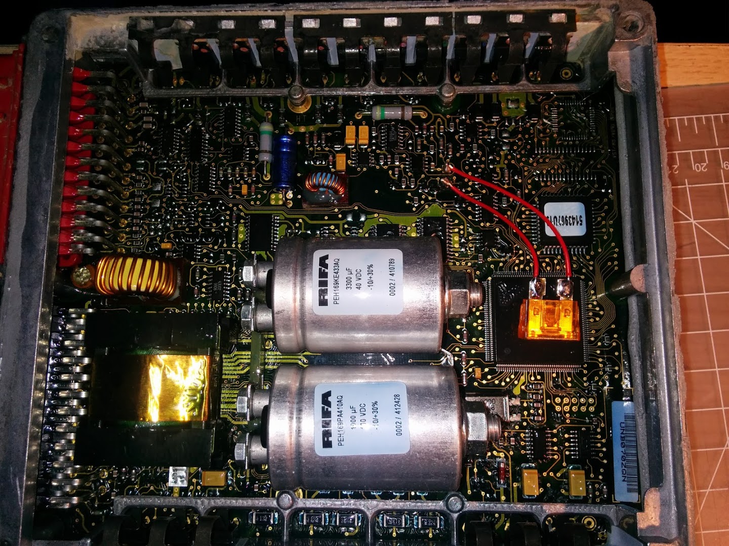
Sure enough popping the lid this link is blown:

Here’s a good one elsewhere on the board:
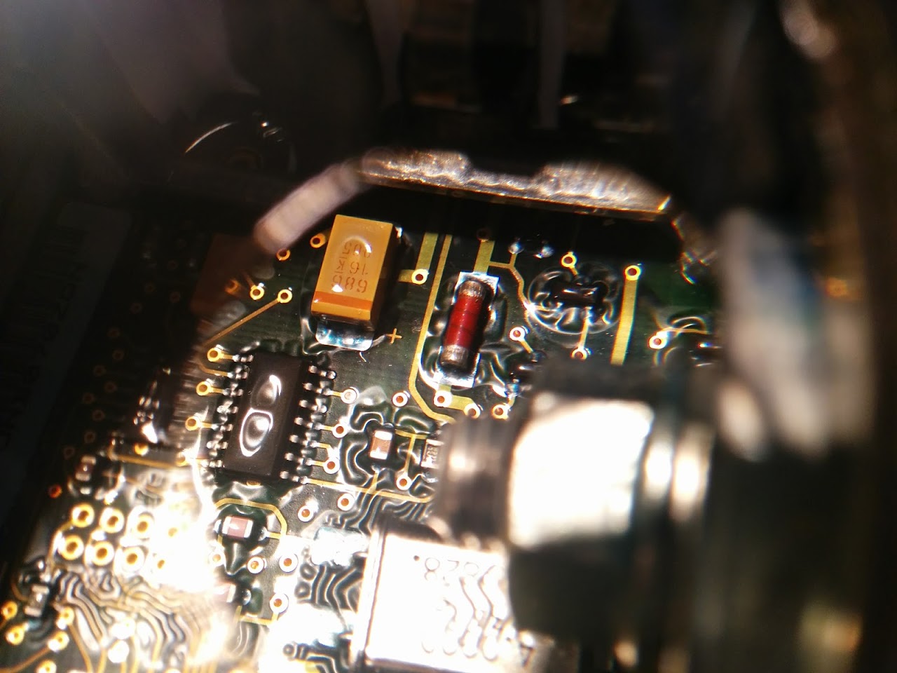
I’m not that up on SMD components, could anyone help with identifying this one or suggesting a suitable replacement other than a direct wire short ![]()
Before you start, ensure you have some spare fuses for your multimeter and know how to replace them.
Tack two wires to the ends of the dead fuse, on the board, or in the fuse holder.
Hook the wires up to the probes on your multimeter, set it in current mode. Multimeters generally have a 10A or thereabouts fuse in line, don’t do this with a cheap arsed Chinese meter, they often have a “fuseable” PCB track rather than a real fuse.
Power on the offending device and measure the current going through the multimeter. Observe the board and the meter carefully for magic smoke, and at the first sign (or smell) of trouble, switch off.
If the multimeter fuse pops, you have a problem with the board, or it draws more than your multimeter can cope with.
If on the other hand, the device operates normally, take the value from the meter, add on a working margin (usually I just double it ‘cos I’m lazy), and fit that size of fuse.
EDIT: From the pictures, my metric calibrated eye would suggest that is a 4A fuse. Let me know if I am correct ![]()
EDIT2: One other clue. The ECU must be powered from the main wiring loom, via a fuse. The value of that fuse is the maximum possible value that your mystery fuse could be, otherwise the main fuse would have blown, rather than the one in the ECU. Your mystery fuse is therefore bound to be smaller than the fuse in the main fuse box that powers the ECU.
In reality I have no idea if it’s a fuse or a resistor, but happy to go with field service experience.
I tried to measure the resistance of the non blown one in circuit, but that didn’t work out too well, tbh it was only ~ 10ohm more than the resistance of the test leads. If it’s a fuse I’d imagine there would not be an alternate path for current to flow and mess up the reading, but if it’s just a resistor I guess there could. My multi-meter is also an automotive one so I doubt it’s particularly sensitive to resistance.
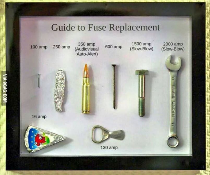
When all is said and done, a fuse is effectively just a bit of wire, designed to melt before the PCB tracks or anything more important blows up.
When all is said and done, a fuse is effectively just a bit of wire, designed to melt before the PCB tracks or anything more important blows up.
When all is said and done, a fuse is effectively just a bit of wire, designed to melt before the PCB tracks or anything more important blows up.
- fuse.JPG (71.53 KiB) Viewed 738 times
That worked fine, however when he came to remove it again… it had welded itself in place..
Enjoy.
Put it in its highest range, (mine has a 5A, on a separate terminal).
Momentarily touch the meter onto the thing you want to measure. You can see straight away by the way the needle kicks, whether its drawing a lot of current.
Wish I had access to all the equipment from when I was at 6th form/Uni, all a bit dated now but quality stuff.
Both pads are lifting from the component overheat ![]()
If it works I’ll hotglue everything in place.
Will it work… course it will ![]()
One other suggestion. Go easy on the hot snot holding down the fuse, you don’t want to pull the chip off the board if you have to replace the new fuse.
If, while testing, the module makes a habit of blowing fuses, swap the automotive fuse for a 20mm fuse holder, perhaps even put it on the outside of the module, and try a bigger fuse. (See Pito’s previous suggestions for a suitable replacement ![]() ) Once you are happy, don’t forget to wrap/coat/seal everything in something to keep the elements out, you don’t want the damp causing difficult to pinpoint issues later.
) Once you are happy, don’t forget to wrap/coat/seal everything in something to keep the elements out, you don’t want the damp causing difficult to pinpoint issues later.
Next job is to swap the PROM chip top right for a socket and an EEPROM.


