Moreover, you can pop up a list of on-screen buttons that send commands back to the MCU.
The API may still change and the Android app isn’t very friendly yet and no doubt there are lots of bugs.
The Android device doesn’t have to be very powerful. It works fine with my $30 Kindle Fire. I’ve been testing both a black pill F103C and a Franken blue pill F303C as the MCU.
Android app: http://github.com/arpruss/vectordisplay
Arduino library: https://github.com/arpruss/vectordisplayarduino
#include <VectorDisplay.h>
VectorDisplayMessage msg;
SerialDisplayClass Display;
void setup() {
Display.begin();
Display.addButton('c', "Circle");
Display.addButton('o', "Color");
}
void loop() {
if (Display.readMessage(&msg) && msg.what == MESSAGE_BUTTON) {
if (msg.data.button == 'c') {
Display.fillCircle(random(240),random(320),random(50));
}
else if (msg.data.button == 'o') {
Display.foreColor(0xFF000000 | (random(256)<<16) | (random(256)<<8) | random(256));
}
}
}
I used it a lot with PIC32 (duino) and it has also a serial display feature within the IDE itselfs.
But a great idea to bring it onto a android based system; most of us are using such phones and even the cheapest one has a better display than our <15 EUR aliexpress/ebay display modules.
Further thinking: ESP8266 WLAN display for STM32duino….
[zoomx – Sun May 27, 2018 8:09 am] –
More further thinking on the Android app: input from bluetooth or WiFi
Brilliant idea. I’ve just abstracted the connection layer, so it should be easy to add now.
WiFiDisplayClass Display;
...
Display.begin("hostIP");
An old Samsung S7500 with cyanogenmod 11 and an ESP-01
The app shows an ip of 87.1.168.192 instead the System information report 192.168.1.97 and so my router
The circle_esp8266 example has a little error
Display.begin(); instead of Display.begin(host);
I have used 192.168.1.97 as host.
After the print “connected” nothin happens, the App report that no devices is connected.
I added some prints after Display.begin() and Display.addButton in setup() and they were printed.
But I found that the S7500 doesn’t reply at ping nor at telnet on port 7788
Then Sony Xperia Z2. The app shows the same ip 87.1.168.192 instead of 192.168.1.87
First time got no connection as before but this time Telnet worked.
Then I disconnected and tested ESP8266 again and this time gon the screen and the two buttons.
I fixed the reversed IP address in the app.
I fixed the begin() line in the example.
I added a few more things to the vector display library for better Adafruit GFX compatibility.
I tested by quickly porting the sketch for my ESP8266 weather warning device, and it correctly displays on my phone rather than on its built in screen. I did have to make sure the WiFi init happened before the screen init, of course.
If you have python examples put them on github, think to a RaspberryPi!
I have to understand why old Samsung S7500 doesn’t work, it seems that the wifi connection is not reliable.
I updated the Android app on the Sony Xperia Z2 (Android 6.0.1) and now the IP is correct.
#include <VectorDisplay.h>
SerialDisplayClass BTScreen(BTSerial);
...
BTSerial.begin();

BTScreen.begin();
I tried the pigscope.ino with it on a ‘bluepill’. I had to change:
define TFT SerialDisplay
to
SerialDisplayClass TFT;
in order for it to compile.
The screen on my Samsung Galaxy S5 does not update though. There is no ‘continuous’ graph. I only see a change when i repeatedly press ‘Hold”. Is there something wrong still with the sketch or the app?
[earl – Thu May 31, 2018 7:31 pm] –
define TFT SerialDisplay
to
SerialDisplayClass TFT;
Nice catch. I changed the API a bit and forgot this.
The screen on my Samsung Galaxy S5 does not update though. There is no ‘continuous’ graph. I only see a change when i repeatedly press ‘Hold”. Is there something wrong still with the sketch or the app?
I don’t know. I just tried it on my HTC A9 with the latest sketch and library and the latest app and it works fine. Are you using the current VectorDisplay library from github (I made changes this morning) and the current app (0.30)?
If you have adb on your PC, I can send you a debug version of the app that records a log and you can send me the log. Email me at [email protected] if interested.
It’s also possible that there is a communication speed issue and the device is sending data too fast and the update calls get missed. You can try two things:
1. Comment out TFT.continuousUpdate(false) and all the TFT.update() calls in the pigscope sketch.
2. Add TFT.setDelay(2) before or after TFT.begin()
Then, I tried these two things:
1. Comment out TFT.continuousUpdate(false) and all the TFT.update() calls in the pigscope sketch.
2. Add TFT.setDelay(2) before or after TFT.begin()
The screen updates (very slow) but only see the dots.. no graph of the signal pulse.
I emailed you to get the debug version. Thanks!
You can get a log with:
adb logcat > log.txt
One comment about the pigscope.ini that I mentioned in the email is this line near the end of the setup() function:
digitalWrite(PB12,1);
shouldn’t that be:
digitalWrite(BOARD_LED,HIGH);
Anyway, I got the debug version and will test it tonight. (Forgot to bring my phone usb cable with me today.)
It does show these lines:
VectorDisplay: Feeding class mobi.omegacentauri.vectordisplay.commands.PolyLine
Probably something incompatible with what I am using. (However I did try, two different bluepills, three different usb/serial adaptors and three different phones.)
Anyway, thanks for looking into this.
I took a look at your pictures of your setup on the play store. I noticed that you are probably using the STM32 bootloader.. and connecting via the USB port. My connection is via a USB/Serial adapter.
So.. I tried it with the bootloader (had to figure that out since I have never used it)..
VectorDisplay works fine when connected via the usb port (with the bootloader)!!!!
However, using a USB/Serial adapter does not work. I tried several different ones. Not sure why.. as other things (loading scripts, comms with other apps) works fine.
Thanks for this useful app!
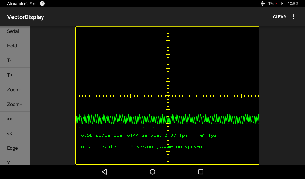
Pigscope works too but only after multiple presses of the “HOLD”. So it probably has to do with so much sent at once continuously. Notice in the trace I sent:
sometimes bad data:
VectorDisplay: bad checksum class mobi.omegacentauri.vectordisplay.commands.PolyLine
and sometimes good data:
VectorDisplay: Feeding class mobi.omegacentauri.vectordisplay.commands.PolyLine
so clearly there is a problem somewhere..
I notice that if you keep the delay(10); and uncomment the blinkLED(); in loop, the display is smoother even using a direct USB connection.
Changing settings in the app does not seem to make much difference.
You will also want to download a new version of the VectorDisplay library for the Arduino side.
This new version works for both USB (bootloader) and USB/Serial adapter. I still need the 100 ms blink delay for the USB/Serial adapter.
Seems to work fine (except for changing the settings).
When i change settings the graph disappears. Have to restart the app to get the screen back.
[earl – Tue Jun 05, 2018 4:26 pm] –
Your app has a menu. Rotate,Clear,Reset,Settings,License… not sure what they all do but i tried ‘Settings’ and changed values which blanked the graph out.
Yeah, after the Settings you probably need to reconnect. I’ll see if I can do something about that. **Update:** I changed Settings into a simple pop-up target FPS chooser.
Right now I am working on bitmap support.


