You just need to supply 5V, and it outputs the “IF” signal, which is be mix product from the transmitter and the incoming received signal.
This is the sum and the difference of the Tx and Rx, but the only usable signal is of course the difference, which is in the audible range, as the sum is 20GHz !
Anyway, looking on the IF output of both the modules I have, it does output a signal, but its very weak and there seems to be a lot of noise.
I did try feeding the IF signal into the input of an audio amplifier but it just seemed to amplify the noise, far more than the signal.
I’m not sure where the noise is coming from, as I’m using a linear PSU, but I will need to try adding some decoupling caps directly to the module
I found this circuit for amplifying the signal from these devices
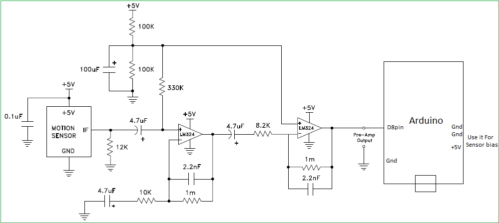
And it looks like I can’t simply use an audio amplifier module for this, as the first opamp stage has a gain of 100 and the second opamp stage seems to be setup to maximum gain, which is probably to create square waves into the Arduino input.
The 2 x 100k resistors and cap in the top left of the circuit, seem to form a voltage divider to produce 2.5V, and I think that voltage is fed into both of the opamps, as a central reference reference voltage.
But I think that possibly that circuit is designed to convert the IF frequency into a voltage as the last opamp is probably configured as an integrator
I found these 2 product data sheets for the HB100
https://www.openimpulse.com/blog/wp-con … asheet.pdf
https://www.openimpulse.com/blog/wp-con … n_Note.pdf
Interestingly the same circuit which is shown as the Arduino interface on www.theorycircuit.com seems to be in the Application Note.
So I’m not convinced whether its the ideal circuit for generating square waves from the output of the module.
I know other people have used this module for doppler speed measurements, so I will need to find the amplifier circuits
Edit.
Direct link to one of those PDF’s
With none signal at the input (disconnect the module but leave the first 12k there) you have to see DC 2.5V (plus minus opamp’s input noise multiplied by amplifier gain, maybe ~hundred(s) of mVpp) at the output of the second opamp. The center (DC) of your signal will always be at 2.5V.
Anything with amplitude bigger than 200uV (inside the band pass freq) will saturate the amplifier (you will get a “square” wave 5V out, or 0.5-2V less) – it depends on the opamp types (ie. rail2rail).
PS: the docs indicates the movement beats around 100-150Hz, so I would decrease the 2.2nF caps to say 1nF in order to get the beat freq inside the bandpass..
Thanks
I don’t have any descrete opamps , but I found this http://www.instructables.com/id/Radar-W … nd-MAX446/ which shows how to convert a MAX446 based microphone sound detector as the amplifier
Its probably not as good as the 2 opamp circuit, but I will try it, as it will be easy to wire up.
With R5=1k you get gain=100, with R5=100ohm you get gain=1000, etc.
Also I would increase the C2 to something like 1uF (ceramic/foil) to move down the input’s highpass freq..
Of course 12000 amplification with a single opamp is usually not to recommend
Yes. I know I need to change the feedback resistor.
I think in that post, the author change the 100k to 1M, so increased the gain by 10 x
I could remove it completely, but I think it would end up being worse as I already have problems with noise
C4=100pF – with that capacitor and 1Meg the upper corner freq will be maybe 2kHz, thus you will get a lot of noise. Your beat signals are up to say 200Hz, so I would increase the C4 to 1nF.
I just looked at the sound detector modules that I have and they are different ![]()
They use a LM393.
I’ll need to see if I can find a schematic for that type, so see if its practical to modify them
Edit. I just looked at the datasheet and the LM393 is a comparitor not an opamp.
PS.
I did try using a class D audio amp module PAM8403 but I had issues with noise ![]()
The useful (your beat) output signal from the module is in range of uV, and only up to couple of hundreds Hertz of frequency. You have to consider that.
Doppler shift output from IF terminal when movement is detected. The magnitude of
the Doppler Shift is proportional to reflection of transmitted energy and is in the range of microvolts (μV). A high gain low frequency amplifier is usually connected to the IF terminal in order to amplify the Doppler shift to a processable level (see Annex 1). Frequency of Doppler shift is proportional to velocity of motion. Typical human walking generates Doppler shift below 100 Hz. Doppler frequency can be calculated by Doppler equation in Annex 4.
The Received Signal Strength (RSS) is the voltage measured of the Doppler shift at the IF output. The RSS figure specified in the technical data sheet is level of a 25 Hz Doppler shift, generate from the modulated microwave signal received at the received antenna, The received microwave signal is attenuated to 93 dB below the transmit microwave signal from the transmit antenna of the same unit. The 93dB loss is the total losses combining two ways free space loss (82.4 dB for 30 meters at 10.525 GHz), reflection less and absorption loss of the target, as well as other losses.
This RSS figure can be view as an approximation of the output signal strength for a human at 15 meters away walking straight to the module at 1.28 km/hour.
The ready to use audio amps are usually 100Hz-20KHz, working with hundreds of mV inputs (low gain). Your signal will be totally lost in the noise (and most probably it will not fit into the amplifier’s bandwidth).
The above schematics with maybe a better opamps (ie. modern low noise) would be definitely my starting point..
My local electronics shop should have the LM324 in stock, so I will drive there at the weekend and buy one (albeit at an inflated price of $2.50 !)
I’ll also take a look in my box of IC’s but I think its mainly old 74xx series
It seems there is only one guy (DaveJ) except you messing with electronics on your continent
Could you use the sections of the BISS0001 PIR detector chip to do your detecting I wonder. After all, it contains a bunch of op amps and comparators.
I see what you mean, but I seem to have damaged 2 of the 3 “Motion sensor” boards, so I don’t know if the opamp chip is still usable.
Though I don’t suppose it would do any harm, to cut the track to the Osc section and try feeding in the IF output from the Doppler module.
I checked through my small stock of ICs and all I had were a few assorted 4000 and 7400 series devices plus a 555 and odds and sods. No OpAmps at all.
Luckily, Australia has a chain of shops called Jaycar which still sell resistors and capacitors and an assortment of ICs, as well as their normal fayre like speaker cable and TV antennas and batteries.
So it’s only a 10 min drive to get common components. ( though at an enflated price)
There is also another smaller chain of stores called Altromics which have a better range of components, but they are around 30 mins drive from where I live, so I only go there if I am desperate to get something in a hurry, as if I am willing to wait a few days where are plenty of EBay vendors in Australia that each seem to see an odd assortment of components
Edit
I just powered up one of the RCWL 9196 based motion detectors which I thought I had fried, but it looks like its still working !
(Despite me applying 5V to its 3V pin!!)
I connected the IF output of the Doppler module into the mic input of my PC, though a 4.7uF cap.
If I record it and then use the Normalise feature in Audacity, I can hear both the noise from my linear PSU and also the dropper audio signal.
So the first problem is to get rid of the supply noise. Because my linear supply was surprisingly noisey when dealing with signals in the millivolt range.
I will need to see how noisey the PC USB or a USB PSU is by comparison, but it looks like getting rid of supply noise many be difficult.
I have a Nucleo F334 board, and the F3 has a built in OpAmp as well as comparitor(s)
http://www.st.com/content/ccc/resource/ … 097745.pdf
So I presume that it would be possible to configure the internal opamp to amplify the signal and possibly to feed its output into a comparator before sampling by a GPIO.
I’ve taken a quick look at the CubeMX to see if its obvious how to configure it, but all I can see is how to enable it, and not how to set the gain or routing
Hopefully @fpstm can shed some light on potentially using the F3 for this.
PS. I will still try using an external opamp, and also the BISxxx chip from the other motion detector.
[ahull – Thu Aug 24, 2017 10:35 pm] –
Sadly I don’t think you would be able to use the 555 as an opamp (unless you are a masochist of course -> http://www.pmonta.com/555-contest/op-amp/op-amp.html ), though it does have two comparators, a flipflop and a buffer.
LOL
Are you sure ![]() They seem to be able to used as virtually any other component
They seem to be able to used as virtually any other component ![]()
I’m not very familiar with opamp.
Have you look inside F3 Cube example:
STM32Cube_FW_F3_V1.8.0\Projects\STM32F334R8-Nucleo\Examples_MIX\OPAMP\OPAMP_CALIBRATION\
you could make a post on https://community.st.com/community/stm32-community
You will have more precise answer.
Anyway I will try to have more information
No worries.
I will see what reference information I can find.
I may also ask Avik De who has the Koduino repo as he is an expert in the F3 series
I’m also trying using an external OpAmp with the F1
I have not had chance to wire up my RCWL 9196 motion detector chip to the Doppler module.
But I tested the 2 RCWL 9196 modules that I had previous been playing with, and only 1 of the 2 is still working
I don’t know if its the RF Osc that has failed or the RCWL 9196, I’m going to unsolder the RF Osc transistor from the defective board and see if the RCWL 9196 is still working.
But if not I can use the other RCWL 9196 that is still working, as I have one more of these boards, which I have not wired up so far.
However, when I tried to connect the IF output from the HB100 into the RCWL 9196, although it amplifies, it seems to have a minimum threshold which means that its only amplifying the signal if it gets quite strong.
I don’t think its worth the hassle of attempting to modify the resistor and capacitor values on this tiny surface mount board
So, I’ll get hold of a LM324 if they have one in stock at the local electronics shop, and build the circuit as recommended in the application data sheet
The output voltage settles at 2.5V when there is no movement, with about 1V of noise.
If I move my hand over the sensor, the output gets driven between 0V and 4V
Ideally when there is no significant movement, I’d rather the output stayed at either 0V or 4V, rather than floating in between
As the LM324 is a quad opamp, I could take the output from the current circuit and feed it into another (3rd) opamp in the same package e.g. feed it into the inverting input, and then bias the non-inverting input to around 1V, which should generally drive the output of a the 3rd opamp to 0V when the output is floating
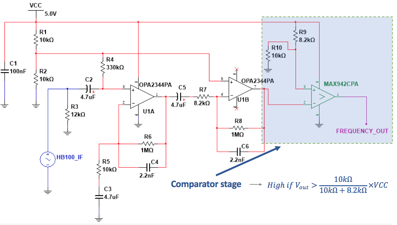
https://medium.com/@benjamindavidfraser … 2d8cacf82e
He used a additional comparator stage
Try to add 100nF-1uF in parallel to first R3=12k (your schematics in previous post).
..you have to see DC 2.5V (plus minus opamp’s input noise multiplied by amplifier gain, maybe ~hundred(s) of mVpp) at the output of the second opamp..
Noise: LM324 could be noisy at such gains (it is rather old general purpose opamp).
Is the noise of higher frequencies?
The best way to limit noise is to decrease the Bandwidth of the amplifier. In case you do not expect fast changes in the movement simply do lower the low-pass corner by increasing the feedback capacitors from 2.2nF to say 10nF or more.
R1/R2 virtual ground must be blocked ie 100uF || 100nF
OK.
I’ll add some extra decoupling to the virtual 2.5V and try adding a cap in parallel with R3
With larger feedback capacities you will see just slow fluctuations around 2.5V (virtual ground) at the output (also the changes due to moving objects will be slower).
The noise will be always there. When you want to mess with speeds measurements or something like that you must DSP the signal somehow..
Or, use “low noise opamp”, there are zillion types out there.
Another option is to use single transistor amplif as the first stage (usually much lower noise).
Another option is to lower the Gain of the opamps (decreasing the 1Meg to 100k-330k for example). Try, maybe the amplification will be enough.
If you want to have signal from zero to 4V you may try to use the third opamp like “opamp peak detector” or “opamp rectifier”.
With using “comparator” at the output you will loose a lot of interesting information in the signal..
Of course the construction style of such high gain amplifier is important too (no ground loops, shielding, etc).
I’ve wired up another of the opamps without any feedback, and have the wiper of a 10k trim pot on the non-inverting input and the output from the previous output (from the 2nd opamp) into the inverting input
(basically the same as that other circuit, except I’m using a 10k pot and an Opamp stage rather than a comparator)
This seems to work quite well, as it cleans up the signal into Highs and Lows (4V and 0V)
I’ll need to add a resistor divider on the output so I can feed it into a Blue pill and attempt some pulse width analysts
I found this interesting article
[RogerClark – Sat Aug 26, 2017 11:37 am] –
Just in case anyone else e.g Andy is interested….I found this interesting article
Thanks. I’ll add that to my to do list. Not sure when I’ll get a chance to build it, as I am in the process of moving house at the moment.
You probably won’t need it if you move to somewhere people are not speeding past ![]()
That device looks like a better quality version of the HB100, and like yiu say…. the HB100 design is probably based on that one.
the key difference is the big reflecting ground plane and the separate antenna PCB
the current status of my HB100 project is that I am getting too much noise from the USB 5V and this is making the system unusable.
i bought the components to rebuild the audio frequency amplifier, but have not had time to build it.
The new circuit uses a low noise, rail to rail, dual opamp, which is run from a separate 3.3V regulator.
To attempt ti remove the supply noise, I was also thinking of using an isolating DC to DC converter, just because I have several of them in my box of spares
But the separate 3.3V regulator may be enough on its own.
http://hforsten.com/third-version-of-ho … radar.html
![[Pending Enhancement] RTC values resetting](https://sparklogic.ru/wp-content/uploads/2019/11/nucleo-l476rg-zestaw-startowy-z-mikrokontrolerem-z-rodziny-stm32-stm32l476-90x90.jpg)