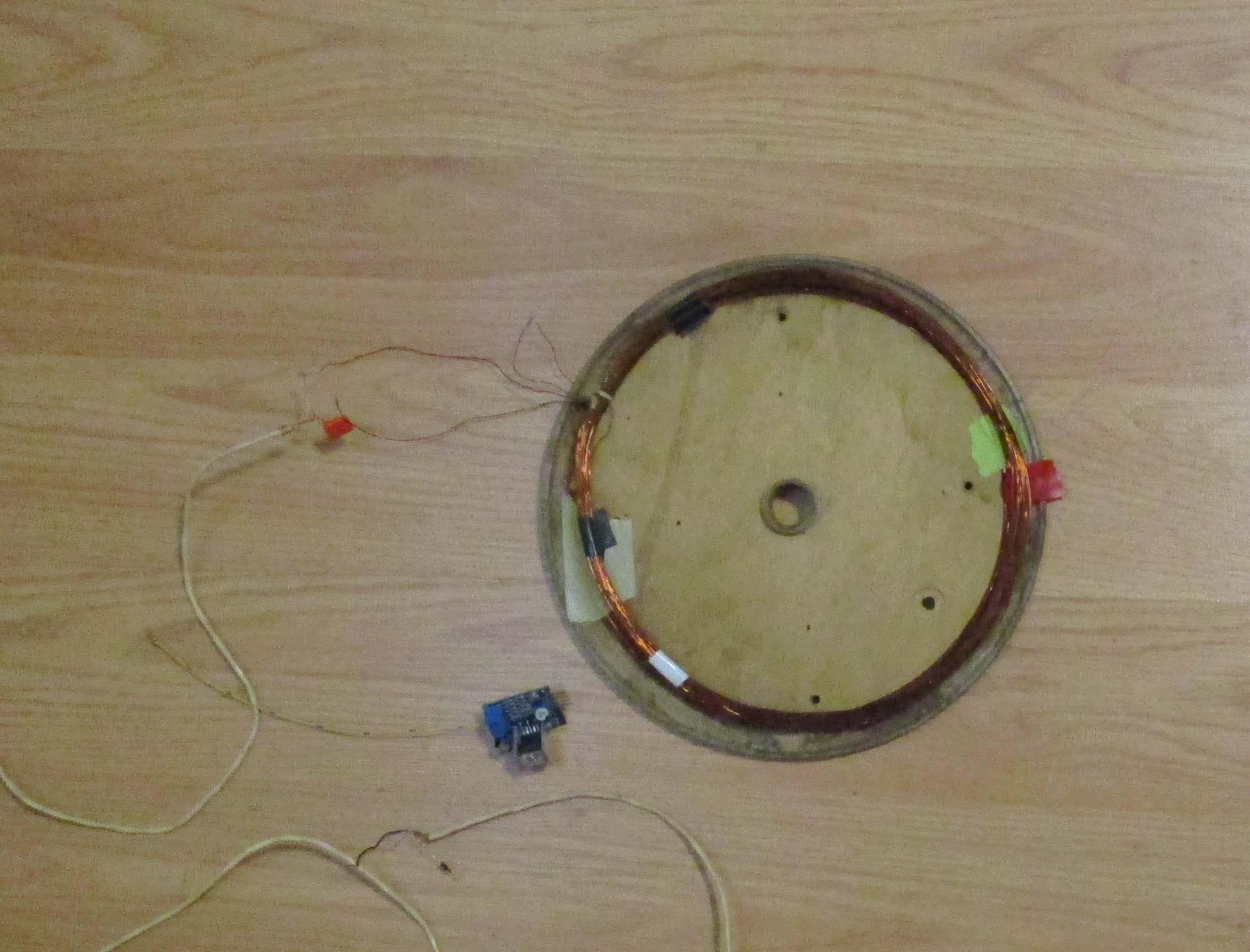
It can be significantly improved by using an audio amplifier to energise Tx coil, the TDA2030 is increasing 20 times the intensity of the electromagnetic field, using serial resonance of Ct and Tx coil.
More improvments can be done by program modifications, I know electronics not programming.
Is there some one interested join me on this improvments ?
https://github.com/dc42/arduino/blob/ma … ematic.jpg
TDA2030; https://m.aliexpress.com/item/32814901629.html
On the subject of audio amplifiers to drive the coil, of an induction balance detector, I did wonder if one of those little class D amplifier boards might do the trick. Class D is theoretically way more efficient, which is a big consideration if operating from batteries. They are also single rail operating devices, which simplifies the power supply.
Search ebay for “DC 5V PAM8403 class D” (also PAM8406, which can drive 5W into 2 ohms at 5V) for the sort of thing I’m talking about.
Designing suitable coils would perhaps be the most problematic part of the process.
There are a couple of other threads about metal detectors on the forum, not sure how far these individuals managed to get.
I will interested to see how your idea pans out. ![]()
I waiting for arrival of arduino board the same as dc42 have used however STM32103 will give better results, it is much faster.
- dc42b.jpg (222.98 KiB) Viewed 1216 times
Assistance with program welcome.
for me, this approach is too complicated: as it relies on the coupling between the two coils for detection. a simpler approach is to use the coil as part of an oscillator, whose frequency changes with the presence of metal (well, most metal) near the coil. thus if you detect the frequency of the coil + metal oscillator, …
that detection can be done by comparing the frequency vs. the internal oscillator, or xtal, …. the most interesting case is to configure the coil + metal as the main oscillator and use other oscillators onboard, like the watchdog timeout to detect frequency shift….
a lowly attiny is more than enough here.
nulling. Mentioned method measuring frequency shift is much les sensitive than Tx-Rx detectors.
you can help yourself by setting realistic design goals and understanding how metal detection works on some metals like aluminum.
On the can it says – Canada. I ordered ATmega328P on Aliexpress with it I am expecting 1m, only 30 cm more. With STM32 would be better but there is need to convert the code from AVR to ARM.
http://hobbycomponents.com/images/forum … 00_600.JPG
#1 code
This is what I an using and Have nathing on LCD.

#include <LiquidCrystal.h>  // recommended by author DC42
// Digital pin definitions
// Digital pin 0 not used, however if we are using the serial port for debugging then it's serial input
const int debugTxPin = 1; // transmit pin reserved for debugging
const int encoderButtonPin = 2; // encoder button, also IN0 for waking up from sleep mode
const int earpiecePin = 3; // earpiece, aka OCR2B for tone generation
const int T0InputPin = 4;
const int coilDrivePin = 5;
const int LcdRsPin = 6;
const int LcdEnPin = 7;
const int LcdRWPin = 0;[b] // added by me for testing
[/b][color=#FF0000][/color]
const int LcdPowerPin = 8; // LCD power and backlight enable
const int T0OutputPin = 9;
const int lcdD0Pin = 10;
const int lcdD1Pin = 11; // pins 11-13 also used for ICSP
const int LcdD2Pin = 12;
const int LcdD3Pin = 13;
To make life simpler, I use an i2c LCD driver, less Pins required, and the library is a drop in replacement, see the LCD Code in this repo -> https://github.com/BennehBoy/TD5EcuEmulator
[ted – Tue Jan 30, 2018 3:37 pm] –
I did that before no success const int LcdRWPin = 0; // added by me for testing
Did what before?
I’m saying DO NOT USE pin 0.
I have a program which has LCD pin description and message which should be displayed. So I add a LiquidCrystal.h library.
I think I should declare the type of used LCD and add the command to run the LCD program.
What I should with R/W and PBS pins ?
See above it’s a SPI device….
So I test my LCD with traditional “hello World” is working ok, this program is using different LCD library and pins.
#2 code
CODE: SELECT ALL
#include “U8glib.h”
//pins used_ E, R/W, RS, PSB.
Read the link I posted…. setup your UNO with ONLY the LCD connected using the pins described in the link. Compile and upload the test sketch that they provide.
#define TIMER1_TOP (249) // can adjust this to fine-tune the frequency to get the coil tuned (see above)
#define USE_3V3_AREF (1) // set to 1 of running on an Arduino with USB power, 0 for an embedded atmega28p with no 3.3V supply available
// Digital pin definitions
// Digital pin 0 not used, however if we are using the serial port for debugging then it's serial input
const int debugTxPin = 1; // transmit pin reserved for debugging
const int encoderButtonPin = 2; // encoder button, also IN0 for waking up from sleep mode
const int earpiecePin = 3; // earpiece, aka OCR2B for tone generation
const int T0InputPin = 4;
const int coilDrivePin = 5;
const int LcdRsPin = 6;
const int LcdEnPin = 7;
const int LcdPowerPin = 8; // LCD power and backlight enable
const int T0OutputPin = 9;
const int lcdD0Pin = 10;
const int lcdD1Pin = 11; // pins 11-13 also used for ICSP
const int LcdD2Pin = 12;
const int LcdD3Pin = 13;
// Analog pin definitions
const int receiverInputPin = 0;
const int encoderAPin = A1;
const int encoderBpin = A2;
// Analog pins 3-5 not used
// Variables used only by the ISR
int16_t bins[4]; // bins used to accumulate ADC readings, one for each of the 4 phases
uint16_t numSamples = 0;
const uint16_t numSamplesToAverage = 1024;
// Variables used by the ISR and outside it
volatile int16_t averages[4]; // when we've accumulated enough readings in the bins, the ISR copies them to here and starts again
volatile uint32_t ticks = 0; // system tick counter for timekeeping
volatile bool sampleReady = false; // indicates that the averages array has been updated
// Variables used only outside the ISR
int16_t calib[4]; // values (set during calibration) that we subtract from the averages
volatile uint8_t lastctr;
volatile uint16_t misses = 0; // this counts how many times the ISR has been executed too late. Should remain at zero if everything is working properly.
const double halfRoot2 = sqrt(0.5);
const double quarterPi = 3.1415927/4.0;
const double radiansToDegrees = 180.0/3.1415927;
// The ADC sample and hold occurs 2 ADC clocks (= 32 system clocks) after the timer 1 overflow flag is set.
// This introduces a slight phase error, which we adjust for in the calculations.
const float phaseAdjust = (45.0 * 32.0)/(float)(TIMER1_TOP + 1);
float threshold = 10.0; // lower = greater sensitivity. 10 is just about usable with a well-balanced coil.
// The user will be able to adjust this via a pot or rotary encoder.
void setup()
{
pinMode(encoderButtonPin, INPUT_PULLUP);
digitalWrite(T0OutputPin, LOW);
pinMode(T0OutputPin, OUTPUT); // pulse pin from timer 1 used to feed timer 0
digitalWrite(coilDrivePin, LOW);
pinMode(coilDrivePin, OUTPUT); // timer 0 output, square wave to drive transmit coil
cli();
// Stop timer 0 which was set up by the Arduino core
TCCR0B = 0; // stop the timer
TIMSK0 = 0; // disable interrupt
TIFR0 = 0x07; // clear any pending interrupt
// Set up ADC to trigger and read channel 0 on timer 1 overflow
#if USE_3V3_AREF
ADMUX = (1 << ADLAR); // use AREF pin (connected to 3.3V) as voltage reference, read pin A0, left-adjust result
#else
ADMUX = (1 << REFS0) | (1 << ADLAR); // use Avcc as voltage reference, read pin A0, left-adjust result
#endif
ADCSRB = (1 << ADTS2) | (1 << ADTS1); // auto-trigger ADC on timer/counter 1 overflow
ADCSRA = (1 << ADEN) | (1 << ADSC) | (1 << ADATE) | (1 << ADPS2); // enable adc, enable auto-trigger, prescaler = 16 (1MHz ADC clock)
DIDR0 = 1;
// Set up timer 1.
// Prescaler = 1, phase correct PWM mode, TOP = ICR1A
TCCR1A = (1 << COM1A1) | (1 << WGM11);
TCCR1B = (1 << WGM12) | (1 << WGM13) | (1 << CS10); // CTC mode, prescaler = 1
TCCR1C = 0;
OCR1AH = (TIMER1_TOP/2 >> 8);
OCR1AL = (TIMER1_TOP/2 & 0xFF);
ICR1H = (TIMER1_TOP >> 8);
ICR1L = (TIMER1_TOP & 0xFF);
TCNT1H = 0;
TCNT1L = 0;
TIFR1 = 0x07; // clear any pending interrupt
TIMSK1 = (1 << TOIE1);
// Set up timer 0
// Clock source = T0, fast PWM mode, TOP (OCR0A) = 7, PWM output on OC0B
TCCR0A = (1 << COM0B1) | (1 << WGM01) | (1 << WGM00);
TCCR0B = (1 << CS00) | (1 << CS01) | (1 << CS02) | (1 << WGM02);
OCR0A = 7;
OCR0B = 3;
TCNT0 = 0;
sei();
while (!sampleReady) {} // discard the first sample
misses = 0;
sampleReady = false;
Serial.begin(19200);
}
// Timer 0 overflow interrupt. This serves 2 purposes:
// 1. It clears the timer 0 overflow flag. If we don't do this, the ADC will not see any more Timer 0 overflows and we will not get any more conversions.
// 2. It increments the tick counter, allowing is to do timekeeping. We get 62500 ticks/second.
// We now read the ADC in the timer interrupt routine instead of having a separate comversion complete interrupt.
ISR(TIMER1_OVF_vect)
{
++ticks;
uint8_t ctr = TCNT0;
int16_t val = (int16_t)(uint16_t)ADCH; // only need to read most significant 8 bits
if (ctr != ((lastctr + 1) & 7))
{
++misses;
}
lastctr = ctr;
int16_t *p = &bins[ctr & 3];
if (ctr < 4)
{
*p += (val);
if (*p > 15000) *p = 15000;
}
else
{
*p -= val;
if (*p < -15000) *p = -15000;
}
if (ctr == 7)
{
++numSamples;
if (numSamples == numSamplesToAverage)
{
numSamples = 0;
if (!sampleReady) // if previous sample has been consumed
{
memcpy((void*)averages, bins, sizeof(averages));
sampleReady = true;
}
memset(bins, 0, sizeof(bins));
}
}
}
void loop()
{
while (!sampleReady) {}
uint32_t oldTicks = ticks;
if (digitalRead(encoderButtonPin) == LOW)
{
// Calibrate button pressed. We save the current phase detector outputs and subtract them from future results.
// This lets us use the detector if the coil is slightly off-balance.
// It would be better to everage several samples instead of taking just one.
for (int i = 0; i < 4; ++i)
{
calib[i] = averages[i];
}
sampleReady = false;
Serial.print("Calibrated: ");
for (int i = 0; i < 4; ++i)
{
Serial.write(' ');
Serial.print(calib[i]);
}
Serial.println();
}
else
{
for (int i = 0; i < 4; ++i)
{
averages[i] -= calib[i];
}
const double f = 200.0;
// Massage the results to eliminate sensitivity to the 3rd harmonic, and divide by 200
double bin0 = (averages[0] + halfRoot2 * (averages[1] - averages[3]))/f;
double bin1 = (averages[1] + halfRoot2 * (averages[0] + averages[2]))/f;
double bin2 = (averages[2] + halfRoot2 * (averages[1] + averages[3]))/f;
double bin3 = (averages[3] + halfRoot2 * (averages[2] - averages[0]))/f;
sampleReady = false; // we've finished reading the averages, so the ISR is free to overwrite them again
double amp1 = sqrt((bin0 * bin0) + (bin2 * bin2));
double amp2 = sqrt((bin1 * bin1) + (bin3 * bin3));
double ampAverage = (amp1 + amp2)/2.0;
// The ADC sample/hold takes place 2 clocks after the timer overflow
double phase1 = atan2(bin0, bin2) * radiansToDegrees + 45.0;
double phase2 = atan2(bin1, bin3) * radiansToDegrees;
if (phase1 > phase2)
{
double temp = phase1;
phase1 = phase2;
phase2 = temp;
}
double phaseAverage = ((phase1 + phase2)/2.0) - phaseAdjust;
if (phase2 - phase1 > 180.0)
{
if (phaseAverage < 0.0)
{
phaseAverage += 180.0;
}
else
{
phaseAverage -= 180.0;
}
}
// For diagnostic purposes, print the individual bin counts and the 2 indepedently-calculated gains and phases
Serial.print(misses);
Serial.write(' ');
if (bin0 >= 0.0) Serial.write(' ');
Serial.print(bin0, 2);
Serial.write(' ');
if (bin1 >= 0.0) Serial.write(' ');
Serial.print(bin1, 2);
Serial.write(' ');
if (bin2 >= 0.0) Serial.write(' ');
Serial.print(bin2, 2);
Serial.write(' ');
if (bin3 >= 0.0) Serial.write(' ');
Serial.print(bin3, 2);
Serial.print(" ");
Serial.print(amp1, 2);
Serial.write(' ');
Serial.print(amp2, 2);
Serial.write(' ');
if (phase1 >= 0.0) Serial.write(' ');
Serial.print(phase1, 2);
Serial.write(' ');
if (phase2 >= 0.0) Serial.write(' ');
Serial.print(phase2, 2);
Serial.print(" ");
// Print the final amplitude and phase, which we use to decide what (if anything) we have found)
if (ampAverage >= 0.0) Serial.write(' ');
Serial.print(ampAverage, 1);
Serial.write(' ');
if (phaseAverage >= 0.0) Serial.write(' ');
Serial.print((int)phaseAverage);
// Decide what we have found and tell the user
if (ampAverage >= threshold)
{
// When held in line with the centre of the coil:
// - non-ferrous metals give a negative phase shift, e.g. -90deg for thick copper or aluminium, a copper olive, -30deg for thin alumimium.
// Ferrous metals give zero phase shift or a small positive phase shift.
// So we'll say that anything with a phase shift below -20deg is non-ferrous.
if (phaseAverage < -20.0)
{
Serial.print(" Non-ferrous");
}
else
{
Serial.print(" Ferrous");
}
float temp = ampAverage;
while (temp > threshold)
{
Serial.write('!');
temp -= (threshold/2);
}
}
Serial.println();
}
while (ticks - oldTicks < 16000)
{
}
}
So I need to change black screen to display message of DC42 program which are on the end of it = activate Serial.print
#1
// include the library code:

//#include <LiquidCrystal.h>

/* Include the U8glib library */

#include "U8glib.h"
/* Define the SPI Chip Select pin */
#define CS_PIN 10
/* Create an instance of the library for the 12864 LCD in SPI mode */
U8GLIB_ST7920_128X64_1X u8g(CS_PIN);
// Induction balance metal detector
// We run the CPU at 16MHz and the ADC clock at 1MHz. ADC resolution is reduced to 8 bits at this speed.
// Timer 1 is used to divide the system clock by about 256 to produce a 62.5kHz square wave.
// This is used to drive timer 0 and also to trigger ADC conversions.
// Timer 0 is used to divide the output of timer 1 by 8, giving a 7.8125kHz signal for driving the transmit coil.
// This gives us 16 ADC clock cycles for each ADC conversion (it actually takes 13.5 cycles), and we take 8 samples per cycle of the coil drive voltage.
// The ADC implements four phase-sensitive detectors at 45 degree intervals. Using 4 instead of just 2 allows us to cancel the third harmonic of the
// coil frequency.
// Timer 2 will be used to generate a tone for the earpiece or headset.
// Other division ratios for timer 1 are possible, from about 235 upwards.
// Wiring:
// Connect digital pin 4 (alias T0) to digital pin 9
// Connect digital pin 5 through resistor to primary coil and tuning capacitor
// Connect output from receive amplifier to analog pin 0. Output of receive amplifier should be biased to about half of the analog reference.
// When using USB power, change analog reference to the 3.3V pin, because there is too much noise on the +5V rail to get good sensitivity.
#define TIMER1_TOP (249) // can adjust this to fine-tune the frequency to get the coil tuned (see above)
#define USE_3V3_AREF (1) // set to 1 of running on an Arduino with USB power, 0 for an embedded atmega28p with no 3.3V supply available
// include the library code:
//#include <LiquidCrystal.h>
/* Include the U8glib library */
#include "U8glib.h"
/* Define the SPI Chip Select pin */
#define CS_PIN 10
/* Create an instance of the library for the 12864 LCD in SPI mode */
U8GLIB_ST7920_128X64_1X u8g(CS_PIN);
// initialize the library by associating any needed LCD interface pin
// with the arduino pin number it is connected to
//const int rs = 6, en = 7, d4 = 10, d5 = 11, d6 = 12, d7 = 13;
//LiquidCrystal lcd(rs, en, d4, d5, d6, d7);
// Digital pin definitions
// Digital pin 0 not used, however if we are using the serial port for debugging then it's serial input
const int debugTxPin = 1; // transmit pin reserved for debugging
const int encoderButtonPin = 2; // encoder button, also IN0 for waking up from sleep mode
const int earpiecePin = 3; // earpiece, aka OCR2B for tone generation
const int T0InputPin = 4;
const int coilDrivePin = 5;
const int LcdEPin = 13;
const int LcdRWPin = 11;
const int LcdRsPin = 10;
//const int LcdRsPin = 6;
//const int LcdEnPin = 7;
const int LcdPowerPin = 8; // LCD power and backlight enable
const int T0OutputPin = 9;
/*
const int lcdD0Pin = 10;
const int lcdD1Pin = 11; // pins 11-13 also used for ICSP
const int LcdD2Pin = 12;
const int LcdD3Pin = 13;
*/
// Analog pin definitions
const int receiverInputPin = 0;
const int encoderAPin = A1;
const int encoderBpin = A2;
// Analog pins 3-5 not used
// Variables used only by the ISR
int16_t bins[4]; // bins used to accumulate ADC readings, one for each of the 4 phases
uint16_t numSamples = 0;
const uint16_t numSamplesToAverage = 1024;
// Variables used by the ISR and outside it
volatile int16_t averages[4]; // when we've accumulated enough readings in the bins, the ISR copies them to here and starts again
volatile uint32_t ticks = 0; // system tick counter for timekeeping
volatile bool sampleReady = false; // indicates that the averages array has been updated
// Variables used only outside the ISR
int16_t calib[4]; // values (set during calibration) that we subtract from the averages
volatile uint8_t lastctr;
volatile uint16_t misses = 0; // this counts how many times the ISR has been executed too late. Should remain at zero if everything is working properly.
const double halfRoot2 = sqrt(0.5);
const double quarterPi = 3.1415927/4.0;
const double radiansToDegrees = 180.0/3.1415927;
// The ADC sample and hold occurs 2 ADC clocks (= 32 system clocks) after the timer 1 overflow flag is set.
// This introduces a slight phase error, which we adjust for in the calculations.
const float phaseAdjust = (45.0 * 32.0)/(float)(TIMER1_TOP + 1);
float threshold = 10.0; // lower = greater sensitivity. 10 is just about usable with a well-balanced coil.
// The user will be able to adjust this via a pot or rotary encoder.
void setup()
{
// set up the LCD's number of columns and rows:
// lcd.begin(16, 2);
// Print a message to the LCD.
//lcd.print("hello, world!");
///////////////////////////////////////////////////////////////
{
/* Start of a picture loop */
u8g.firstPage();
/* Keep looping until finished drawing screen */
do
{
/* Set the font */
u8g.setFont(u8g_font_courB14);
// #1
///////////////////////////////////////////////////////////
/* Display some text */
u8g.drawStr( 35, 26, "HOBBY");
u8g.drawStr( 8, 46, "COMPONENTS");
/* Draw a simple border */
u8g.drawFrame(5,5,117,54);
u8g.drawFrame(3,3,121,58);
}while(u8g.nextPage());
}
pinMode(encoderButtonPin, INPUT_PULLUP);
digitalWrite(T0OutputPin, LOW);
pinMode(T0OutputPin, OUTPUT); // pulse pin from timer 1 used to feed timer 0
digitalWrite(coilDrivePin, LOW);
pinMode(coilDrivePin, OUTPUT); // timer 0 output, square wave to drive transmit coil
cli();
// Stop timer 0 which was set up by the Arduino core
TCCR0B = 0; // stop the timer
TIMSK0 = 0; // disable interrupt
TIFR0 = 0x07; // clear any pending interrupt
// Set up ADC to trigger and read channel 0 on timer 1 overflow
#if USE_3V3_AREF
ADMUX = (1 << ADLAR); // use AREF pin (connected to 3.3V) as voltage reference, read pin A0, left-adjust result
#else
ADMUX = (1 << REFS0) | (1 << ADLAR); // use Avcc as voltage reference, read pin A0, left-adjust result
#endif
ADCSRB = (1 << ADTS2) | (1 << ADTS1); // auto-trigger ADC on timer/counter 1 overflow
ADCSRA = (1 << ADEN) | (1 << ADSC) | (1 << ADATE) | (1 << ADPS2); // enable adc, enable auto-trigger, prescaler = 16 (1MHz ADC clock)
DIDR0 = 1;
// Set up timer 1.
// Prescaler = 1, phase correct PWM mode, TOP = ICR1A
TCCR1A = (1 << COM1A1) | (1 << WGM11);
TCCR1B = (1 << WGM12) | (1 << WGM13) | (1 << CS10); // CTC mode, prescaler = 1
TCCR1C = 0;
OCR1AH = (TIMER1_TOP/2 >> 8);
OCR1AL = (TIMER1_TOP/2 & 0xFF);
ICR1H = (TIMER1_TOP >> 8);
ICR1L = (TIMER1_TOP & 0xFF);
TCNT1H = 0;
TCNT1L = 0;
TIFR1 = 0x07; // clear any pending interrupt
TIMSK1 = (1 << TOIE1);
// Set up timer 0
// Clock source = T0, fast PWM mode, TOP (OCR0A) = 7, PWM output on OC0B
TCCR0A = (1 << COM0B1) | (1 << WGM01) | (1 << WGM00);
TCCR0B = (1 << CS00) | (1 << CS01) | (1 << CS02) | (1 << WGM02);
OCR0A = 7;
OCR0B = 3;
TCNT0 = 0;
sei();
while (!sampleReady) {} // discard the first sample
misses = 0;
sampleReady = false;
Serial.begin(19200);
}
// Timer 0 overflow interrupt. This serves 2 purposes:
// 1. It clears the timer 0 overflow flag. If we don't do this, the ADC will not see any more Timer 0 overflows and we will not get any more conversions.
// 2. It increments the tick counter, allowing is to do timekeeping. We get 62500 ticks/second.
// We now read the ADC in the timer interrupt routine instead of having a separate comversion complete interrupt.
ISR(TIMER1_OVF_vect)
{
++ticks;
uint8_t ctr = TCNT0;
int16_t val = (int16_t)(uint16_t)ADCH; // only need to read most significant 8 bits
if (ctr != ((lastctr + 1) & 7))
{
++misses;
}
lastctr = ctr;
int16_t *p = &bins[ctr & 3];
if (ctr < 4)
{
*p += (val);
if (*p > 15000) *p = 15000;
}
else
{
*p -= val;
if (*p < -15000) *p = -15000;
}
if (ctr == 7)
{
++numSamples;
if (numSamples == numSamplesToAverage)
{
numSamples = 0;
if (!sampleReady) // if previous sample has been consumed
{
memcpy((void*)averages, bins, sizeof(averages));
sampleReady = true;
}
memset(bins, 0, sizeof(bins));
}
}
}
void loop()
{
while (!sampleReady) {}
uint32_t oldTicks = ticks;
if (digitalRead(encoderButtonPin) == LOW)
{
// Calibrate button pressed. We save the current phase detector outputs and subtract them from future results.
// This lets us use the detector if the coil is slightly off-balance.
// It would be better to everage several samples instead of taking just one.
for (int i = 0; i < 4; ++i)
{
calib[i] = averages[i];
}
sampleReady = false;
Serial.print("Calibrated: ");
for (int i = 0; i < 4; ++i)
{
Serial.write(' ');
Serial.print(calib[i]);
}
Serial.println();
}
else
{
for (int i = 0; i < 4; ++i)
{
averages[i] -= calib[i];
}
const double f = 200.0;
// Massage the results to eliminate sensitivity to the 3rd harmonic, and divide by 200
double bin0 = (averages[0] + halfRoot2 * (averages[1] - averages[3]))/f;
double bin1 = (averages[1] + halfRoot2 * (averages[0] + averages[2]))/f;
double bin2 = (averages[2] + halfRoot2 * (averages[1] + averages[3]))/f;
double bin3 = (averages[3] + halfRoot2 * (averages[2] - averages[0]))/f;
sampleReady = false; // we've finished reading the averages, so the ISR is free to overwrite them again
double amp1 = sqrt((bin0 * bin0) + (bin2 * bin2));
double amp2 = sqrt((bin1 * bin1) + (bin3 * bin3));
double ampAverage = (amp1 + amp2)/2.0;
// The ADC sample/hold takes place 2 clocks after the timer overflow
double phase1 = atan2(bin0, bin2) * radiansToDegrees + 45.0;
double phase2 = atan2(bin1, bin3) * radiansToDegrees;
if (phase1 > phase2)
{
double temp = phase1;
phase1 = phase2;
phase2 = temp;
}
double phaseAverage = ((phase1 + phase2)/2.0) - phaseAdjust;
if (phase2 - phase1 > 180.0)
{
if (phaseAverage < 0.0)
{
phaseAverage += 180.0;
}
else
{
phaseAverage -= 180.0;
}
}
//#2
//////////////////////////////////////////////////////////////////////////////
// For diagnostic purposes, print the individual bin counts and the 2 indepedently-calculated gains and phases
Serial.print(misses);
Serial.write(' ');
if (bin0 >= 0.0) Serial.write(' ');
Serial.print(bin0, 2);
Serial.write(' ');
if (bin1 >= 0.0) Serial.write(' ');
Serial.print(bin1, 2);
Serial.write(' ');
if (bin2 >= 0.0) Serial.write(' ');
Serial.print(bin2, 2);
Serial.write(' ');
if (bin3 >= 0.0) Serial.write(' ');
Serial.print(bin3, 2);
Serial.print(" ");
Serial.print(amp1, 2);
Serial.write(' ');
Serial.print(amp2, 2);
Serial.write(' ');
if (phase1 >= 0.0) Serial.write(' ');
Serial.print(phase1, 2);
Serial.write(' ');
if (phase2 >= 0.0) Serial.write(' ');
Serial.print(phase2, 2);
Serial.print(" ");
// Print the final amplitude and phase, which we use to decide what (if anything) we have found)
if (ampAverage >= 0.0) Serial.write(' ');
Serial.print(ampAverage, 1);
Serial.write(' ');
if (phaseAverage >= 0.0) Serial.write(' ');
Serial.print((int)phaseAverage);
// Decide what we have found and tell the user
if (ampAverage >= threshold)
{
// When held in line with the centre of the coil:
// - non-ferrous metals give a negative phase shift, e.g. -90deg for thick copper or aluminium, a copper olive, -30deg for thin alumimium.
// Ferrous metals give zero phase shift or a small positive phase shift.
// So we'll say that anything with a phase shift below -20deg is non-ferrous.
if (phaseAverage < -20.0)
{
Serial.print(" Non-ferrous");
}
else
{
Serial.print(" Ferrous");
}
float temp = ampAverage;
while (temp > threshold)
{
Serial.write('!');
temp -= (threshold/2);
}
}
Serial.println();
}
while (ticks - oldTicks < 16000)
{
}
}
[BennehBoy – Thu Feb 01, 2018 8:09 am] –
I suspect you may be better served …
I think ted is just keeping us updated on his progress .. like a project log.
Ray
He is showing what kind of problems he is facing and is looking for answers to them.
He is showing what kind of problems he is facing and is looking for answers to them.
No problem ted. We’ve all been there, C++ isn’t anybody’s native tongue, after all.
But when looking for answers, do accept when the answer is “you need to take a step back, and start basic“. Really, you’re trying to solve specific problems, and of course, finding a solution to those problems is exactly why you’re looking at programming in the first place. But even though you may feel real close to solving those problems with your current method of copy-and-paste, what you seem to totally underestimate is your lack of understanding of just how any of what your copying actually works (on the level of programming). Sorry to say, but that lack is fundamental and you will get nowhere trying to ignore it. Better understanding will not come to, automatically, just by spending more time on your approach. Instead, what you need to do is to go back and work through some basic tutorials. Focusing on “Hello world!” may look like a huge step backwards, but you are not ever going to get to your real goals, if you don’t take the time to understand every single line of such basic examples. Yes, a whole lot of that will already be familiar to you. Don’t let that fool you. You still need to understand the basics, completely.
Since you say you have a firm grip on the electronics side, and you don’t need help with basic tasks such as installing or uploading, try these tutorials, focussed on programming basics: https://startingelectronics.org/softwar … am-course/. All of them, please. And again, you need to understand every single line of code in these tutorials. That is going to take some time (not forever, though) and effort (not a superhero effort, though), but there is not shortcut to learning the basics.
Cheers!
program any info is appreciated.
https://www.researchgate.net/post/How_t … tch_filter
I presume you are trying to remove mains hum, but you haven’t fully described your problem. You might find it easier to do your filtering with one or more R/C or L/C electronic filters. This would take some of the load off your processor. Sometimes it is simpler to throw a few op-amps and some passives at a problem than to try to compute the solution in real time. Especially since “mains hum” can have lots of lovely harmonics that trip you up too.
Related in the sense that this series of videos tells you in a relatively digestible format *how* removal of a particular frequency from a bunch of frequencies actually works.
For those of you who consider your maths is a little rusty, you might like to go through the “unit circle” stuff first in the following series of videos to get a grip of the underlying trig concepts.
Also a read through of this related thread… -> viewtopic.php?t=1145&start=30#p14677
… and the video here …
might be worth your time too.
with an FIR filter you can get for example this (click on “Source Code”, select ie. Number format: Integer and 32bit int precision and copy/paste the source) – LINK is in the picture below:
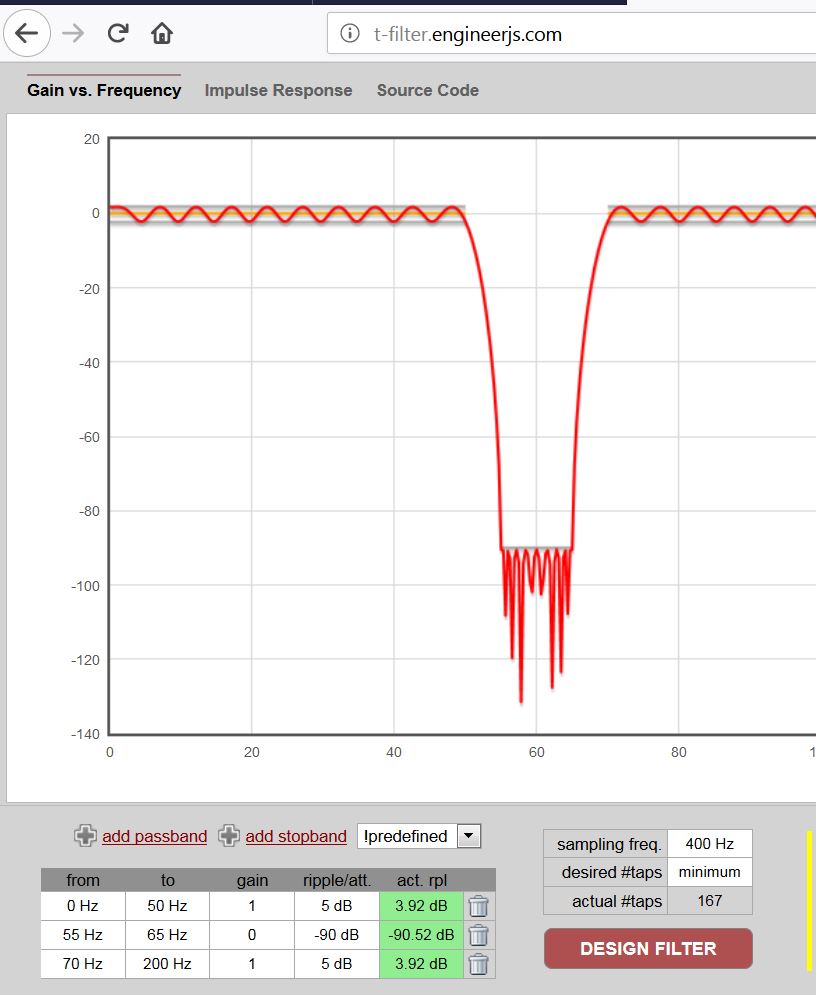
- 60Hz bandstop_minus 90db.JPG (85.54 KiB) Viewed 309 times
..

#include "SampleFilter.c"

..

int32_t signal;  // the actual ADC signal sample

int32_t fsig;  // internal FIR filter variable
setup() {

..

SampleFilter_init(&fsig);  // you have to init the FIR filter

..

}
HERE IS A 400Hz SAMPLING LOOP >>>>>
signal = readAnalog(PA4);  // get 12bit signal sample
SampleFilter_put(&fsig, signal);  // pass the signal into the FIR filter

signal = SampleFilter_get(&fsig);  // read the signal from the FIR filter

..

DO SOMETHING WITH THE FILTERED signal

..

<<<<<  END OF THE 400Hz SAMPLING LOOP
Here is the code which was working before but when I saved it and opened again the PWM on pin PB1 is not there any more. In this program is also notch filter.
#include <FIRFilter.h>

#include <IIRFilter.h>
const float ECG_samplefreq = 360;
const uint8_t ECG_pin = PB0;
const int16_t DC_offset = 511;
//const uint8_t ECG_pin = PB1; //output pin
int outputPin = PB1; //output pin
//int outputPin = PA6; //output pin
// 50 Hz notch
//const float b_notch[] = { 1.39972748302835, -1.79945496605670, 1.39972748302835 };
/*
// 35 Hz Butterworth low-pass
const float b_lp[] = { 0.00113722762905776, 0.00568613814528881, 0.0113722762905776, 0.0113722762905776, 0.00568613814528881, 0.00113722762905776 };
const float a_lp[] = { 1, -3.03124451613593, 3.92924380774061, -2.65660499035499, 0.928185738776705, -0.133188755896548 };
*/
const float a_coefficients[] = {1, 3.610968072739773, 5.096060175734044, 3.317095275389235, 0.844114606367055};
const float b_coefficients[] = {0.003306153133358, 0, -0.006612306266715, 0, 0.003306153133358};
/*
// 0.3 Hz high-pass
const float b_hp[] = { 1, -1 };
const float a_hp[] = { 1, -0.995 };
FIRFilter notch(b_notch);
//IIRFilter lp(b_lp, a_lp);
IIRFilter hp(b_hp, a_hp);
*/
void setup() {
Serial.begin(115200);
}
unsigned long ECG_prevmicros = micros();
void loop() {
const static unsigned long ECG_interval = round(1e6 / ECG_samplefreq);
if (!Serial) {
ECG_prevmicros = micros();
} else if (micros() - ECG_prevmicros >= ECG_interval) {
measureECGAndSend();
ECG_prevmicros += ECG_interval;
}
}
void measureECGAndSend() {
int16_t value = analogRead(ECG_pin);
float filtered = //notch.filter(
//lp.filter(
// hp.filter(value - DC_offset));
value = round((filtered) + DC_offset);
Serial.println(value);
//Serial.print(value); // PWM on PB1
value = map(value, 0, 1023, 0, 255);
value = constrain(value, 0, 255);
analogWrite(outputPin, value); // output pin
}
I have read everything including the link, but with my programming knowledge I am not able to put everything together.


