- 20170123_101108.jpg (184.7 KiB) Viewed 934 times
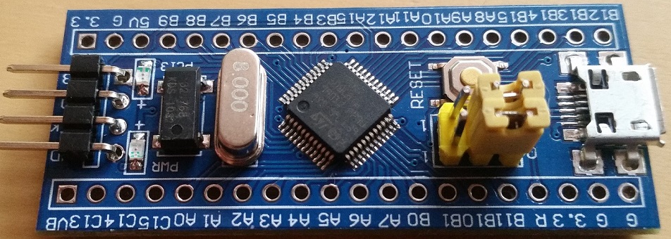
If it isn’t the USB connector then my next guess would be the voltage regulator, or… you powered up using USB *and* had the 3v3 connected from the ST-Link at the same.. That seems to cause the voltage regulator to take a fit or even pop. Check to see if the regulator is getting 5V in, and spitting 3v3 out.
If it isn’t the USB connector then my next guess would be the voltage regulator, or… you powered up using USB *and* had the 3v3 connected from the ST-Link at the same.. That seems to cause the voltage regulator to take a fit or even pop. Check to see if the regulator is getting 5V in, and spitting 3v3 out.
If it isn’t the USB connector then my next guess would be the voltage regulator, or… you powered up using USB *and* had the 3v3 connected from the ST-Link at the same.. That seems to cause the voltage regulator to take a fit or even pop. Check to see if the regulator is getting 5V in, and spitting 3v3 out.
EDIT: .. and if your soldering skills are up to it, put some more solder on the tabs that hold the USB connectors to the board. This is a well known weakness. The USB connectors are easily parted from the board anyway, but the solder on those tabs on the one in the pictures is almost non-existent.
EDIT: .. and if your soldering skills are up to it, put some more solder on the tabs that hold the USB connectors to the board. This is a well known weakness. The USB connectors are easily parted from the board anyway, but the solder on those tabs on the one in the pictures is almost non-existent.
I took leave of my senses, and decided to attempt to resolder the micro usb connector, and by some miracle all three of the boards are now powering up, and two of the three successfully enumerated as Maple DFU devices, and I flashed a test ECC routine which they both ran successfully and re-enumerated as serial ports! Success, though now I have to figure out how you flash them a second time as they appear as serial ports rather than DFU devices, though I’m sure there’s a FAQ on dealing with that.
The third board which is one of the batch of two from the same supplier, rather than the single one from a different supplier, is powering up and running fine BUT appears as an unknown USB device.The STM32duino boot loader flashes it’s LEDs correctly, and the board runs code uploaded through the STlink fine.
I’ve checked continuity through a cut off microusb cable, and tested that the cut off microusb cable’s wires are connected to PA12 & PA11, and that ground, and 5v are also connected. Further more, I’ve checked that the 10k (should be 1.5k according to USB specs, but well known Blue Pill issue) pull up resistor is connected correctly as well. The other two boards both have 10k pullups and they enumerate and program fine, so evidently the USB hub I’ve got isn’t strict.
Lastly I’ve checked that there aren’t any shorts between the USB pins. So it seems to me that the only thing left to check is whether or not PA11 & PA12 are actually connected to the MCU. For that I suppose I can write a test program that waggles the pins up and down and see if that appears on the PA11 & PA12 breakout.
Is there anything else I’m missing in terms of a diagnostic process on this one remaining board? I know the boards functional and working apart from the USB, so it seems to me that I’ve conducted all the USB connectivity tests possible already, with the exception of confirming that PA11/PA12 are actually attached to the MCU?
Thanks once again for the assistance, it’s much appreciated.
… now I have to figure out how you flash them a second time as they appear as serial ports rather than DFU devices, though I’m sure there’s a FAQ on dealing with that.
… now I have to figure out how you flash them a second time as they appear as serial ports rather than DFU devices, though I’m sure there’s a FAQ on dealing with that.
