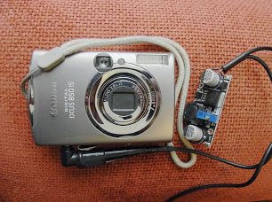
I am a total novice, planning to use a Blue Pill as an intervalometer, controlling the power to a time lapse rig consisting of a Canon point and shoot camera (using the CHDK – Canon Hackers Development Kit), and a Raspberry Pi.
The power for this remote placed rig will likely come from a cheap, chinese, 6 LiPo battery pack

https://www.ebay.com.au/itm/121957836096
which can output either of the two voltages I need for the components ie. 3.7v for the camera and 5v for the Raspberry Pi. I plan to buy the safest chemistry Lithium Iron Phosphate (LiFePO4) batteries for the pack. Can anyone suggest the most efficient method for boosting the 3.7v up to 5v, so I can power both devices at the same time, or perhaps regulating down the 5v output to 3.7? I’ve read that linear regulators are wasteful in heating up while buck converters are pretty good. Is boosting a voltage up more wasteful than regulating a voltage down?
I’m hoping I can add power measurement to the BluePill sketch such that it will sense when the power pack is getting near the low threshold for safety and stop the power supply. Is this even possible and could someone link me to some tutorial or a sample sketch?
Thanks in advance
Sdack
Bunch of pictures here -> https://plus.google.com/u/0/photos/1110 … 6731304017
I just ordered a couple of those LM2596 buck converters.
Originally I misunderstood the ebay item as being able to ‘simultaneously’ output the two voltages, but that’s ok.
I pm’d you on the CHDK forum, hope that’s ok. I’m very excited about my time laspse adventures, since getting a nice result yesterday morning in my neighbour’s field.
https://www.vimeo.com/239930114
Best wishes
N
Hi Andy,
The parts for my extended, internet connected, time lapse rig are arriving bit by bit on the slow boat finally.
I did think rather than a PM, I should start a thread for this but I’m not sure where to put it. If you advise, I’ll transfer it to an appropriate place in the forum.
I have been reading up yours and other folks DIY 18650 power packs and have decided it seems the best way to go, so I’ve ordered one of these units:
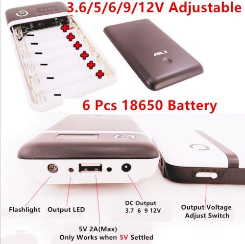
ebay link here
https://www.ebay.com.au/itm/121957836096
I plan to go with the safest battery type I can find, which seem to be the Li-phosphate chemistry, which I read, doesn’t burn when exposed to air (if punctured) – http://batteryuniversity.com/learn/arti … _batteries
Aside from overloading the batteries on recharge, which comes down to the quality of the charger, the issue seems to be making sure they don’t drop below their lower voltage safety limit, I read, I think in one of your posts, that because Canon point and shoots, shut down themselves, when the voltage isn’t high enough, that provides a secondary level of safety, beyond whatever protection circuitry there may be in the cheap power pack itself.
The reason I chose this model was because it offers both 3.6v AND 5v outputs, which are the desired voltages for the Canon AND my Raspberry Pi controller that handles the internet upload of images. Because the Blue Pill STM32 microcontroller will be powering up the Raspberry Pi I’m wondering if there’s some way to add, voltage detection, to the Arduino sketch, so that it will cease when the voltage approaches the lower safety threshold? I’m not yet familiar enough with the capabilities of the STM. Should I post on the STM forum too?
I just read in this thread https://chdk.setepontos.com/index.php?topic=12749.0 in the final post by Axman,
Quote
Lessons learned so far: (some seen elsewhere in this forum, and some learned from burnt fingers)
Try to mimic cam’s functions when operated by a human more closely (use the on-off sw if possible).
Affix wires to their final locations before attempting to solder tiny wires to paper-thin switch contacts.
Try not to get it too hot – obviously.
Don’t over-voltage – give the cam close to what it expects but not more – kind of obvious..
if possible, leave the power On inside the battery house throughout a day’s cycling,
rather than cutting power each time –
the resulting power switch on-off action seems more reliable.
This and the fact that the power button on my Ixus160 seems very small with little movement, makes me wonder whether I could leave the camera on during the shooting day (construction – 8.30 am – 4.30 pm ish). Do you know if there are any figures for the power draw in a low power state, or if there even is such a thing?
Finally, do you think I’m taking too much of a risk with this chinese unit? Can you recommend any other, easily implemented safety features I can put in place to avoid the kind of fireworks I’ve seen on YouTube?
Cheers
Nigel
First point last. “do you think I’m taking too much of a risk with this chinese unit?” … not really, these units are probably no better or worse than the sort of thing you get in Asda/Tesco/Wallmart or wherever. They are what they are. So long as you keep them dry and don’t let the lipos get too cold (< -18C) or too hot (> +40C) then you should be fine.
So far as the power button on the camera is concerned, I would avoid surgery if possible.
I would tape down the camera power button, as it should then power up automatically when you apply the power through the dummy battery.
Do you know if there are any figures for the power draw in a low power state, or if there even is such a thing?
Search the CHDK forum, I’m sure there is a thread that does in to this in some detail.
I did think rather than a PM, I should start a thread for this but I’m not sure where to put it.
Put it in the “Hotwire! Hardware Mods, Accessories and Insights” section of the CHDK forum. I’m sure a lot of people would be interested, and willing to contribute their experiences.
I am in the process of moving house at the moment, so my apologies if I am as responsive as I usually am for the next few weeks.
[ahull – Fri Oct 27, 2017 9:21 am] – First point last. “do you think I’m taking too much of a risk with this chinese unit?” … not really, these units are probably no better or worse than the sort of thing you get in Asda/Tesco/Wallmart or wherever. They are what they are. So long as you keep them dry and don’t let the lipos get too cold (< -18C) or too hot (> +40C) then you should be fine.
Is 40C really the cut-off for these lipo packs? Eek. Can’t use them in the summer around here, then.
We’ve had some days above 45 deg last year.
Particularly charging at elevated temperatures >45C, and below freezing may be a problem.
[ahull – Mon Oct 30, 2017 8:47 pm] –
I think they will still work beyond these extremes, but their capacity will be affected.
Particularly charging at elevated temperatures >45C, and below freezing may be a problem.
Good to know. Fortunately, I don’t charge batteries (except car batteries) outdoors.
[ahull – Fri Oct 27, 2017 9:21 am] –
Hi, hope you don’t mind if I post your CHDK PM here.
Not at all.. thanks for that
The below item arrived and seems reasonably sturdy.. I’m not quite game for a teardown.. might not get it back together again!
ebay link here
https://www.ebay.com.au/itm/121957836096
I plan to go with the safest battery type I can find, which seem to be the Li-phosphate chemistry, which I read, doesn’t burn when exposed to air (if punctured) – http://batteryuniversity.com/learn/arti … _batteries
scratch that.. I decided to go with a local (ie. Australian), supplier and a brand name batteries which came up on special a couple of days ago..
Genuine LG HE4 2500mah 20A Lithium Rechargeable battery
https://www.techaroundyou.com/Vape-Batt … upply-bulk
and a 6 slot charger to go with the 6 batteries
https://www.techaroundyou.com/Chargers/ … CD-Charger
Total cost AUD $95, which seems a lot but the charger was $55 of that and the batteries only cost 6.50 each. I went for ‘high drain’ ones having read they’re more capable. Even though there were some 2600mah 30A Sony’s available for only a dollar more each.
https://www.techaroundyou.com/Genuine-V … upply-bulk
I am in the process of moving house at the moment, so my apologies if I am as responsive as I usually am for the next few weeks.
Hope your move went well.. it can be quite unsettling hey!
Cheers
Sdack
I suspect you can possibly get them a little cheaper elsewhere.
The batteries in the KMart power bank are labelled “Great Power”, which sounds like a Chinese brand.
and have a manufactuing date on them of 20170522 as well as the max charge voltage
I’ve not tested yet to confirm the capacity is whats written on them.
I’m hoping for good results from the LG high drain batteries I just ordered but I will need to swap in an alternate power pack when they are charging.
Now that I’ve got my Blue Pill actually working (at least programmable via ST-Link), I’m starting my hunt for sketches which will combine power monitoring and scheduling the powering on and off of the relays to supply my camera and Raspberry Pi set up.
I’ve been rather surprised at the level of complexity of the code I’m seeing in the example sketches. I’m more used to bash and python scripting which seems simpler somehow. Perhaps it’s because several of the scripts I’ve looked at include hardware interfaces, like touchscreens for user input.
If anyone can point me towards a simple timing sketch to control switching on a schedule like the following.. I’d appreciate it
SHEDULE
Mon – Fr
8:30 – 4:30
switch on relay for X mins every X minutes
I’m looking for a sketch which will put the microprocessor in some kind of sleep mode inbetween scheduled events. From what I’m reading, this might require an external RTC, running on a coin cell battery.
Cheers and have a great weekend
Sdack
It should not be too hard to write.
@ahull wrote a sunset / sunrise timer thingy to operate a camera, so perhaps you can look for his code, its on the forum or his github account
BTW.
Relays take a lot of current, I’m not sure how that works with a low power system.
But perhaps you only turn them on for a short time
You could potentially also use a FET instead of a relay, as they take virtually no switching current
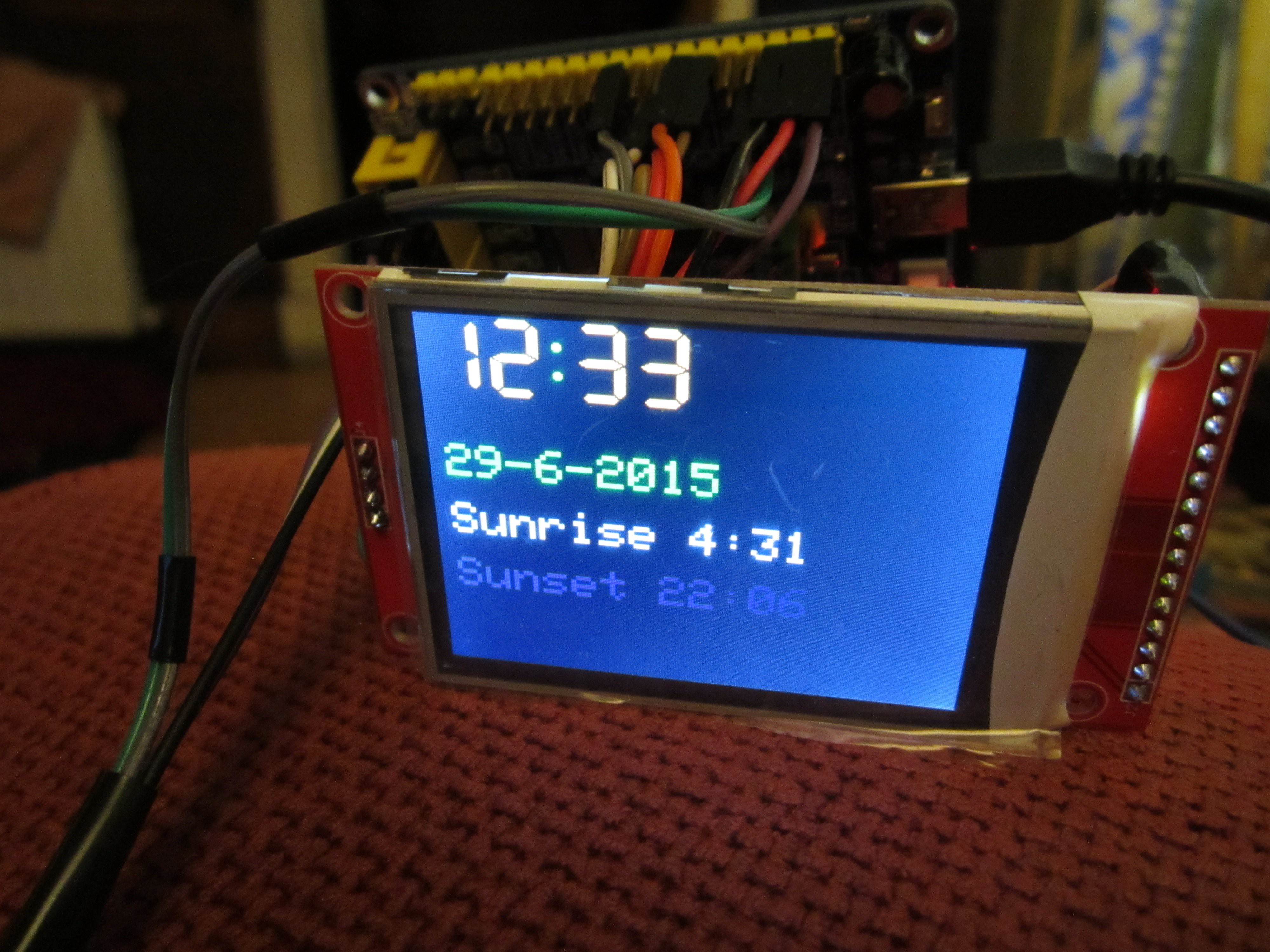
It was AHull’s Sunset timer that got me started down this road. I just revisited his Hackaday page https://hackaday.io/project/2126-sunset … controller and you are correct in that he uses dual mosfets as his switches.
I have looked through his code and it’s a bit daunting. Lots of stuff in there for the Nokia display.
I guess my best and shortest route to a workable start would be to duplicate his system as close as possible and take it from there.
AliExpress, here I come again!
N
It uses the ILI9341 display. Its been a while since I looked at the code though, and since I’m still fighting with the chaos of moving house, I have no clue where the prototype is… ![]() I did have it working with both relays, and Mosfets. For sunrise or sunset timelapses, the power used by a relay is not too bad, the camera only runs for about a half hour per day, and the camera itself is the major drain on the battery.
I did have it working with both relays, and Mosfets. For sunrise or sunset timelapses, the power used by a relay is not too bad, the camera only runs for about a half hour per day, and the camera itself is the major drain on the battery.
/*.

(c) Andrew Hull - 2015

STM32-Sunrise - Released under the GNU GENERAL PUBLIC LICENSE Version 3

Sunrise and sunset timer.

https://github.com/pingumacpenguin/STM32-Sunrise

Adafruit Libraries released under their specific licenses Copyright (c) 2013 Adafruit Industries.  All rights reserved.

Honourable mention to https://stackoverflow.com/users/1678716/scottmrogowski Scott m Rogowski for the detailed sunrise calculation code posted here.

https://stackoverflow.com/questions/7064531/sunrise-sunset-times-in-c/9425781#9425781?newreg=23a1112cbf764135b2cc16a678d032de

I have plagerised this unashamedly, since it is neat, tidy and *almost* worked first time. A few enhancements allow both sunset and sunrise to be caluclated with the same function,

so I added a couple of wrapper functions to keep the code size down.

All other libraries are detailed with appopriate links in the code comments.

*/
#include "Adafruit_ILI9341_STM.h"
#include "Adafruit_GFX_AS.h"
// Be sure to use the latest version of the SPI libraries see stm32duino.com - http://stm32duino.com/viewtopic.php?f=13&t=127
#include <SPI.h>
#define PORTRAIT 0
#define LANDSCAPE 1
// Define the orientation of the touch screen. Further
// information can be found in the UTouch library documentation.
#define TOUCH_SCREEN_AVAILABLE
#define TOUCH_ORIENTATION LANDSCAPE
#if defined TOUCH_SCREEN_AVAILABLE
// UTouch Library
// http://www.rinkydinkelectronics.com/library.php?id=56
#include <UTouch.h>
#endif
// Initialize touchscreen
// ----------------------
// Set the pins to the correct ones for your STM32F103 board
// -----------------------------------------------------------
//
// STM32F103C8XX Pin numbers - chosen for ease of use on the "Red Pill" and "Blue Pill" board
// Touch Panel Pins
// T_CLK T_CS T_DIN T_DOUT T_IRQ
// PB12 PB13 PB14 PB15 PA8
// Example wire colours Brown,Red,Orange,Yellow,Violet
// -------- Brown,Red,Orange,White,Grey
#if defined TOUCH_SCREEN_AVAILABLE
UTouch myTouch( PB12, PB13, PB14, PB15, PA8);
#endif
// RTC and NVRam initialisation
#include "RTClock.h"
RTClock rt (RTCSEL_LSE); // initialise
uint32 tt;
// Define the Base address of the RTC registers (battery backed up CMOS Ram), so we can use them for config of touch screen and other calibration.
// See http://stm32duino.com/viewtopic.php?f=15&t=132&hilit=rtc&start=40 for a more details about the RTC NVRam
// 10x 16 bit registers are available on the STM32F103CXXX more on the higher density device.
#define BKP_REG_BASE (uint32_t *)(0x40006C00 +0x04)
// Defined for power and sleep functions pwr.h and scb.h
#include <libmaple/pwr.h>
#include <libmaple/scb.h>
// #define NVRam register names for the touch calibration values.
#define TOUCH_CALIB_X 0
#define TOUCH_CALIB_Y 1
#define TOUCH_CALIB_Z 2
// Time library - https://github.com/PaulStoffregen/Time
#include "Time.h"
#define TZ "UTC+1"
// End RTC and NVRam initialization
// SeralCommand -> https://github.com/kroimon/Arduino-SerialCommand.git
#include <SerialCommand.h>
/* For reference on STM32F103CXXX
variants/generic_stm32f103c/board/board.h:#define BOARD_NR_SPI 2
variants/generic_stm32f103c/board/board.h:#define BOARD_SPI1_NSS_PIN PA4
variants/generic_stm32f103c/board/board.h:#define BOARD_SPI1_MOSI_PIN PA7
variants/generic_stm32f103c/board/board.h:#define BOARD_SPI1_MISO_PIN PA6
variants/generic_stm32f103c/board/board.h:#define BOARD_SPI1_SCK_PIN PA5
variants/generic_stm32f103c/board/board.h:#define BOARD_SPI2_NSS_PIN PB12
variants/generic_stm32f103c/board/board.h:#define BOARD_SPI2_MOSI_PIN PB15
variants/generic_stm32f103c/board/board.h:#define BOARD_SPI2_MISO_PIN PB14
variants/generic_stm32f103c/board/board.h:#define BOARD_SPI2_SCK_PIN PB13
*/
// Additional display specific signals (i.e. non SPI) for STM32F103C8T6 (Wire colour)
#define TFT_DC PA0 // (Green)
#define TFT_CS PA1 // (Orange)
#define TFT_RST PA2 // (Yellow)
// Hardware SPI1 on the STM32F103C8T6 *ALSO* needs to be connected and pins are as follows.
//
// SPI1_NSS (PA4) (LQFP48 pin 14) (n.c.)
// SPI1_SCK (PA5) (LQFP48 pin 15) (Brown)
// SPI1_MOSO (PA6) (LQFP48 pin 16) (White)
// SPI1_MOSI (PA7) (LQFP48 pin 17) (Grey)
//
#define TFT_LED PA3 // Backlight
#define TEST_WAVE_PIN PB0 // PWM 500 Hz
// Relay pins
#define RELAY_1 PC4
#define RELAY_2 PC5
// Create the lcd object
Adafruit_ILI9341_STM TFT = Adafruit_ILI9341_STM(TFT_CS, TFT_DC, TFT_RST); // Using hardware SPI
// LED - blinks on trigger events - leave this undefined if your board has no controllable LED
// define as PC13 on the "Red/Blue Pill" boards and PD2 on the "Yellow Pill R"
#define BOARD_LED PD2
// Display colours
#define BEAM1_COLOUR ILI9341_GREEN
#define BEAM2_COLOUR ILI9341_RED
#define GRATICULE_COLOUR 0x07FF
#define BEAM_OFF_COLOUR ILI9341_BLACK
#define CURSOR_COLOUR ILI9341_GREEN
// Screen dimensions
int16_t myWidth ;
int16_t myHeight ;
// Create Serial Command Object.
SerialCommand sCmd;
// Create USB serial port
USBSerial serial_debug;
// Sunrise stuff
#include <math.h>
#define PI 3.1415926
#define ZENITH -.83
/*
#define Stirling_Latitude 56.138607900000000000
#define Stirling_Longitude -3.944080100000064700
*/
// Lat long for your location
#define HERE_LATITUDE 56.1386079
#define HERE_LONGITUDE -3.9440801
int thisYear = 2015;
int thisMonth = 6;
int thisDay = 27;
int lastDay = 0;
int thisHour = 0;
int thisMinute = 0;
int thisSecond = 0;
float thisLat = HERE_LATITUDE;
float thisLong = HERE_LONGITUDE;
float thisLocalOffset = 0;
int thisDaylightSavings = 1;
// Digital clock variables
byte omm = 0;
//byte ss=0;
byte xcolon = 0;
void setup()
{
// Check time, and set a sensible time, if this board has no battery, or the time is unset
tt = rt.getTime();
// Check to see if we are close to the epoch, and if so, bad things must have happened to the RTC backup power domain.
if ( tt < 1024 )
{
// Set to a recent value - 29th June 2015 12:25 (just after mid day)
rt.setTime(1435580711);
// BOARD_LED blinks on events assuming you have an LED on your board. If not simply dont't define it at the start of the sketch.
// TODO: make the board blink a morse code for the error.
pinMode(RELAY_1, OUTPUT);
pinMode(RELAY_2, OUTPUT);
#if defined BOARD_LED
pinMode(BOARD_LED, OUTPUT);
digitalWrite(BOARD_LED, HIGH);
digitalWrite(RELAY_1, LOW);
digitalWrite(RELAY_2, HIGH);
delay(1000);
digitalWrite(BOARD_LED, HIGH);
digitalWrite(RELAY_1, HIGH);
digitalWrite(RELAY_2, LOW);
delay(1000);
#endif
}
// BOARD_LED blinks on events assuming you have an LED on your board. If not simply dont't define it at the start of the sketch.
#if defined BOARD_LED
pinMode(BOARD_LED, OUTPUT);
digitalWrite(BOARD_LED, HIGH);
delay(1000);
digitalWrite(BOARD_LED, LOW);
delay(1000);
#endif
serial_debug.begin();
//
// Serial command setup
// Setup callbacks for SerialCommand commands
sCmd.addCommand("timestamp", setCurrentTime); // Set the current time based on a unix timestamp
sCmd.addCommand("date", serialCurrentTime); // Show the current time from the RTC
sCmd.addCommand("sleep", sleepMode); // Experimental - puts system to sleep
#if defined TOUCH_SCREEN_AVAILABLE
// sCmd.addCommand("touchcalibrate", touchCalibrate); // Calibrate Touch Panel
#endif
sCmd.setDefaultHandler(unrecognized); // Handler for command that isn't matched (says "Unknown")
sCmd.clearBuffer();
// Backlight, use with caution, depending on your display, you may exceed the max current per pin if you use this method.
// A safer option would be to add a suitable transistor capable of sinking or sourcing 100mA (the ILI9341 backlight on my display is quoted as drawing 80mA at full brightness)
// Alternatively, connect the backlight to 3v3 for an always on, bright display.
//pinMode(TFT_LED, OUTPUT);
//analogWrite(TFT_LED, 127);
// Setup Touch Screen
// http://www.rinkydinkelectronics.com/library.php?id=56
#if defined TOUCH_SCREEN_AVAILABLE
myTouch.InitTouch();
myTouch.setPrecision(PREC_EXTREME);
#endif
TFT.begin();
// initialize the display
clearTFT();
TFT.setRotation(PORTRAIT);
myHeight = TFT.width() ;
myWidth = TFT.height();
TFT.setTextColor(CURSOR_COLOUR, BEAM_OFF_COLOUR) ;
#if defined TOUCH_SCREEN_AVAILABLE
// touchCalibrate();
#endif
TFT.setRotation(LANDSCAPE);
clearTFT();
//delay(5000) ;
//clearTFT();
}
void loop() {
// Setting the clock from the serial port is a matter of doing this in Linux...
// NOW=$(date --date "+1hour" +"%s"); echo -e "\n\ntimestamp $NOW\n\n" >/dev/ttyACMx
// where /dev/ttyACMx is the tty of the STM board. In my case /dev/ttyACM3
// You can't do this if something else, for example tha arduino Serial Monitor, is attached to the port.
sCmd.readSerial(); // Process serial commands
// Show time, date, sunrise and sunset, rinse, repeat }:¬)
tt = rt.getTime();
thisYear = year(tt);
thisMonth = month(tt);
thisDay = day(tt);
thisHour = hour(tt);
thisMinute = minute(tt);
thisSecond = second(tt);
// drawRoundRect(uint16_tx0,uint16_ty0,uint16_tw,uint16_th,uint16_tradius,uint16_tcolor);
TFT.drawRoundRect(8, 8, 160, 60, 5, 0xFBE0);
TFT.drawRoundRect(6, 6, 164, 64, 5, 0xFBE0);
TFT.setTextSize(1);
TFT.setCursor(20, 20);
//
showTime();
TFT.setTextSize(3);
if (lastDay != thisDay) {
TFT.setCursor(10, 80);
TFT.setTextColor(ILI9341_GREEN);
showDate();
}
lastDay = thisDay;
TFT.setTextColor(thisMinute * (thisSecond + 1) * 65535);
TFT.setCursor(10, 120);
showSunrise();
TFT.setTextColor(255 * thisHour * (thisSecond + 30) + 10);
TFT.setCursor(10, 160);
showSunset();
//TFT.drawCentreString("12.34",60,91,7);
// serialCurrentTime();
TFT.setTextColor(ILI9341_GREEN);
}
float calculateSunrise(int year, int month, int day, float lat, float lng, int localOffset, int daylightSavings ) {
boolean rise = 1;
return calculateSunriseSunset(year, month, day, lat, lng, localOffset, daylightSavings, rise) ;
}
float calculateSunset(int year, int month, int day, float lat, float lng, int localOffset, int daylightSavings ) {
boolean rise = 0;
return calculateSunriseSunset(year, month, day, lat, lng, localOffset, daylightSavings, rise) ;
}
//
float calculateSunriseSunset(int year, int month, int day, float lat, float lng, int localOffset, int daylightSavings, boolean rise) {
/*
localOffset will be <0 for western hemisphere and >0 for eastern hemisphere
daylightSavings should be 1 if it is in effect during the summer otherwise it should be 0
*/
//1. first calculate the day of the year
float N1 = floor(275 * month / 9);
float N2 = floor((month + 9) / 12);
float N3 = (1 + floor((year - 4 * floor(year / 4) + 2) / 3));
float N = N1 - (N2 * N3) + day - 30;
//2. convert the longitude to hour value and calculate an approximate time
float lngHour = lng / 15.0;
float t = 0;
if (rise ) {
t = N + ((6 - lngHour) / 24); //if rising time is desired:
}
else
{
t = N + ((18 - lngHour) / 24); //if setting time is desired:
}
//3. calculate the Sun's mean anomaly
float M = (0.9856 * t) - 3.289;
//4. calculate the Sun's true longitude
float L = fmod(M + (1.916 * sin((PI / 180) * M)) + (0.020 * sin(2 * (PI / 180) * M)) + 282.634, 360.0);
//5a. calculate the Sun's right ascension
float RA = fmod(180 / PI * atan(0.91764 * tan((PI / 180) * L)), 360.0);
//5b. right ascension value needs to be in the same quadrant as L
float Lquadrant = floor( L / 90) * 90;
float RAquadrant = floor(RA / 90) * 90;
RA = RA + (Lquadrant - RAquadrant);
//5c. right ascension value needs to be converted into hours
RA = RA / 15;
//6. calculate the Sun's declination
float sinDec = 0.39782 * sin((PI / 180) * L);
float cosDec = cos(asin(sinDec));
//7a. calculate the Sun's local hour angle
float cosH = (sin((PI / 180) * ZENITH) - (sinDec * sin((PI / 180) * lat))) / (cosDec * cos((PI / 180) * lat));
/*
if (cosH > 1)
the sun never rises on this location (on the specified date)
if (cosH < -1)
the sun never sets on this location (on the specified date)
*/
//7b. finish calculating H and convert into hours
float H = 0;
if (rise ) {
//serial_debug.print("#sunrise");
H = 360 - (180 / PI) * acos(cosH); // if if rising time is desired:
//serial_debug.println(H);
}
else
{
//serial_debug.print("# sunset ");
H = (180 / PI) * acos(cosH); // if setting time is desired:
//serial_debug.println(H);
}
//float H = (180/PI)*acos(cosH) // if setting time is desired:
H = H / 15;
//8. calculate local mean time of rising/setting
float T = H + RA - (0.06571 * t) - 6.622;
//9. adjust back to UTC
float UT = fmod(T - lngHour, 24.0);
//10. convert UT value to local time zone of latitude/longitude
return UT + localOffset + daylightSavings;
}
void showSunrise() {
float localT = calculateSunrise(thisYear, thisMonth, thisDay, thisLat, thisLong, thisLocalOffset, thisDaylightSavings);
double hours;
float minutes = modf(localT, &hours) * 60;
TFT.print("Sunrise ");
TFT.print(uint(hours));
TFT.print(":");
if (uint(minutes) < 10) {
TFT.print("0");
}
TFT.print(uint(minutes));
}
void showSunset() {
float localT = calculateSunset(thisYear, thisMonth, thisDay, thisLat, thisLong, thisLocalOffset, thisDaylightSavings);
double hours;
float minutes = modf(24 + localT, &hours) * 60;
TFT.print("Sunset ");
TFT.print(uint(24 + localT));
TFT.print(":");
if (uint(minutes) < 10) {
TFT.print("0");
}
TFT.print(uint(minutes));
}
void setCurrentTime() {
char *arg;
arg = sCmd.next();
String thisArg = arg;
serial_debug.print("# Time command [");
serial_debug.print(thisArg.toInt() );
serial_debug.println("]");
setTime(thisArg.toInt());
time_t tt = now();
rt.setTime(tt);
//serialCurrentTime();
}
void serialCurrentTime() {
serial_debug.print("# Current time - ");
if (hour(tt) < 10) {
serial_debug.print("0");
}
serial_debug.print(hour(tt));
serial_debug.print(":");
if (minute(tt) < 10) {
serial_debug.print("0");
}
serial_debug.print(minute(tt));
serial_debug.print(":");
if (second(tt) < 10) {
serial_debug.print("0");
}
serial_debug.print(second(tt));
serial_debug.print(" ");
serial_debug.print(day(tt));
serial_debug.print("/");
serial_debug.print(month(tt));
serial_debug.print("/");
serial_debug.print(year(tt));
//serial_debug.println("("TZ")");
}
void unrecognized(const char *command) {
serial_debug.print("# Unknown Command.[");
serial_debug.print(command);
serial_debug.println("]");
}
void clearTFT()
{
TFT.fillScreen(BEAM_OFF_COLOUR); // Blank the display
}
void showTime ()
{
tt = rt.getTime();
////////
// Update digital time
byte xpos = 14;
byte ypos = 14;
byte mm = minute(tt);
byte hh = hour(tt);
byte ss = second(tt);
if (omm != mm) { // Only redraw every minute to minimise flicker
TFT.setTextColor(ILI9341_BLACK, ILI9341_BLACK); // Set font colour to back to wipe image
// Font 7 is to show a pseudo 7 segment display.
// Font 7 only contains characters [space] 0 1 2 3 4 5 6 7 8 9 : .
TFT.drawString("88:88", xpos, ypos, 7); // Overwrite the text to clear it
TFT.setTextColor(0xFBE0, ILI9341_BLACK); // Orange
omm = minute(tt);
if (hh < 10) xpos += TFT.drawChar('0', xpos, ypos, 7);
xpos += TFT.drawNumber(hh, xpos, ypos, 7);
xcolon = xpos;
xpos += TFT.drawChar(':', xpos, ypos, 7);
if (mm < 10) xpos += TFT.drawChar('0', xpos, ypos, 7);
TFT.drawNumber(mm, xpos, ypos, 7);
}
if (ss % 2) { // Flash the colon
TFT.setTextColor(0x39C4, ILI9341_BLACK);
//delay(500);
xpos += TFT.drawChar(':', xcolon, ypos, 7);
TFT.setTextColor(0xFBE0, ILI9341_BLACK);
//delay(500);
relayOneOff();
relayTwoOn();
}
else {
TFT.drawChar(':', xcolon, ypos, 7);
uint32 colour = ILI9341_GREEN;
//uint32 colour = 0x39C4;
// Erase the text with a rectangle
//TFT.fillRect (0, 48, 160, 20, ILI9341_BLACK);
TFT.setTextColor(colour);
//TFT.drawRightString("Colour", 75, 64, 4); // Right justified string drawing to x position 75
//String scolour = String(colour, HEX);
//scolour.toUpperCase();
//char buffer[20];
//scolour.toCharArray(buffer, 20);
//TFT.drawString(buffer, 82, 64, 4);
relayOneOn();
relayTwoOff();
}
}
void showDate ()
{
// Show RTC Time.
tt = rt.getTime();
TFT.print(day(tt));
TFT.print("-");
TFT.print(month(tt));
TFT.print("-");
TFT.print(year(tt));
}
// STM32F103XXXX sleep mode
void sleepMode()
{
serial_debug.println("# Nighty night!");
// Set PDDS and LPDS bits for standby mode, and set Clear WUF flag (required per datasheet):
PWR_BASE->CR |= PWR_CR_CWUF;
PWR_BASE->CR |= PWR_CR_PDDS;
// set sleepdeep in the system control register
SCB_BASE->SCR |= SCB_SCR_SLEEPDEEP;
// Now go into stop mode, wake up on interrupt
// disableClocks();
asm("wfi");
}
void relayOneOn()
{
pinMode(RELAY_1, OUTPUT);
digitalWrite(RELAY_1, LOW);
}
void relayOneOff()
{
pinMode(RELAY_1, OUTPUT);
digitalWrite(RELAY_1, HIGH);
}
void relayTwoOn()
{
pinMode(RELAY_2, OUTPUT);
digitalWrite(RELAY_2, LOW);
}
void relayTwoOff()
{
pinMode(RELAY_2, OUTPUT);
digitalWrite(RELAY_2, HIGH);
}
To be honest the learning curve is a lot steeper than I’d imagined. Every step of the way there’s a component I’ve only vaguely heard of and never used, along with the various derivative devices and languages etc.
I really appreciate the help.
Sdack
Thanks for posting
I’m currently building a LoRa (wireless) beacon, so that code may come in handy to get the beacon to come on every 15 secs and give a pulse
Cheers
Roger
https://www.adafruit.com/product/1651
I Googled and found a link to it via Roger Clarke’s GitHub page
https://github.com/rogerclarkmelbourne/ … LI9341_STM
s
Try searching ebay for “SPI ILI9341 240×320”
This one looks like it is probably the same.
https://www.ebay.co.uk/itm/240×320-2-4- … SwstxVZ8f3