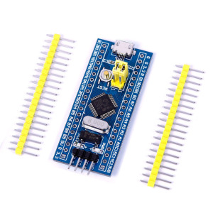
Stm32f103c8 Mini Board
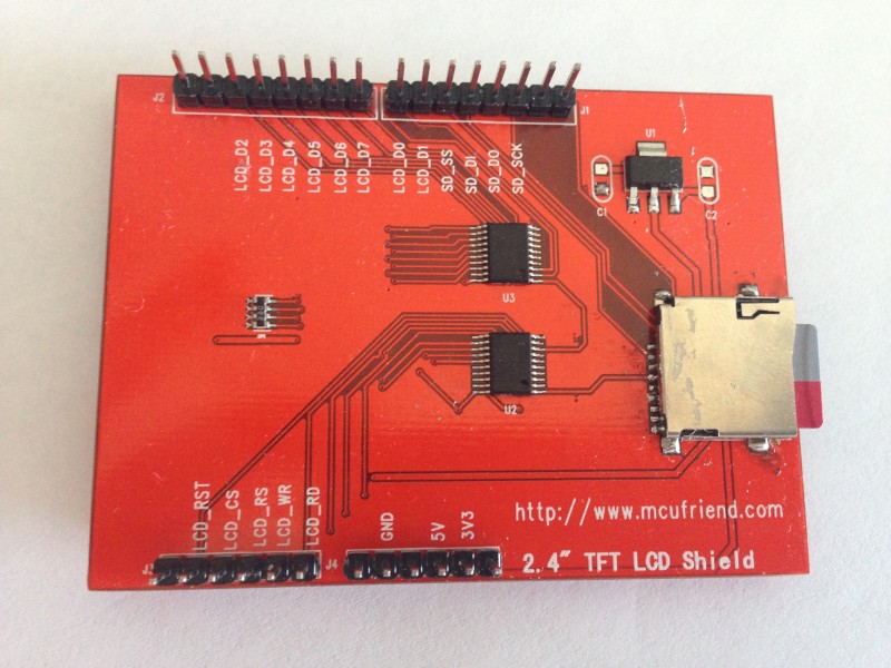
ili9325 2.4” TFT (arduino uno compotible)
HI
How do I program with these two products arduino ide
thanks!
But you have to put your hands on the lib (I assume it’s 8-bit parallel driven).
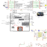
Stm32F103C Board Pin -> TFT pin wiring diagram

This connection type is correct
It also does not display a pin LCD_CD
LCD_RS same with LCD CD?
I think there’s a problem
look at an 8080 type interface for the control pins and use
stephen
Working library: https://github.com/iwalpola/Adafruit_ILI9341_8bit_STM/
JoaoLopes’s library supports ILI9341, and this one probably is an ILI9341. I checked the SPFD5408 datasheet, and Joao’s library definitely isn’t for SPFD5408. I wonder why he named it so.
I’m in this exact same situation. Are you sure that the TFT driver IC is ILI9325?
I have seen working Arduino Uno libraries for this shield from several sources, including https://github.com/JoaoLopesF/SPFD5408. And they say that the IC is “SPFD5408”.
Joao Lopes’s library above uses a modified version of the Adafruit TFT library for the hardware layer. The Adafruit TFT library was originally for controlling ILIxxxx series of IC, but this guy modified it for the 8 bit interface of SPFD508.
Now, I’ve seen working code examples for STM32 for the ILIxxxx on Andy’s Workshop blog http://andybrown.me.uk/2012/01/01/stm32 … ft-driver/. So I’m tracking where Joao changed the Adafruit library to try and figure out how to modify an STM32 driver for this TFT.
Okay, I did a git diff on the SPFD5408 library and the Adafruit TFTLCD (for ILI9325 in 8 bit mode) library. Only one thing has been changed, and that is the readID function (it reads a register to identify the chip) which isn’t a big change at all. So I think an STM32 8 bit interface library for ILI9325 should work for the SPFD5408 as well. I’ll look for one or modify andy’s workshop code.
2.8” – ILI???? – http://www.aliexpress.com/item/2-8-inch … 20242.html
3.5” – ILI9486 (parallel 16 bit) – http://www.aliexpress.com/item/Fashiona … 29793.html
The speed of 8 bit transfers opens up a lot of options
http://www.stm32duino.com/viewtopic.php … =637#p6641
viewtopic.php?f=44&t=637&p=15438#p15438
github:
https://github.com/iwalpola/Adafruit_ILI9341_8bit_STM/
demo:
https://www.youtube.com/watch?v=MAkMaZyZMWM
https://github.com/stevstrong/Adafruit_ … 8bit_STM32
Benchmark is available here.
And also developed a touch screen lib which has some nice features (repeated touch, double touch), check the tftpaint.ino example of the touch library for details.
https://github.com/stevstrong/TouchScreen_STM32
- ili9328_small.jpg (38.35 KiB) Viewed 3207 times
![]()
![]()
Now I’m looking for some really slim, small and cheap battery package, anyone already has a reference?
Idea is to marry the TFT with a good battery, use it like an arcade game console and/or power bank.
What do you think?
Poundworld do a powerbank (for a pound obviously) which is around the 700mAh to 1000mAh marker.
https://goo.gl/photos/tPzqL6q7R9HSaSCK6

https://goo.gl/photos/ECQkQ62rnNL8Pde96

Here is a portable web server base on this idea, that I happened to have to hand.
(Also the capacity wasnt as advertised, only 2000mAH rather than 4000mAH)
So I ended up just keeping it to charge my mobile phone.
The better option is to get hold of the battery separately and also use one of those charger / regulator output modules (like in Andy’s photo), as those little modules, always have their output turned on (apart from when the battery voltage goes below a usable threshold) and they don’t have the voltage converter circuity like in the power bank, which does the buck conversion from 3.7V to 5V -, as this just wastes power as its not needed when powering the STM32
BTW. Think someone else posted about buying batteries and expecting half the capacity they claim, but ended up with 20% of the claimed capacity ![]()
Hopefully those won’t be quite as badly miss-advertised
Yes, I can just hope that it will give more than 1000mAh, will see.
no extra postage increase, at least for 4 off
something nicely round about £10’ish
second link, no UK delivery
stephen
I’m not sure routing TFT with STM32, I can’t find B2 port.
And how connect you supply??
Thanks
For Battery power bank:
You can easily use an 18650 battery. Is a lithium battery.
You can buy it at aliexpress, and a USB charger,
And how connect you supply??
Wich drivers are better to use an ILI93471 8 bit paralel in arduino uno shield with a Blue pill STM32f103C.
If i use a stev strong driver i dont have B2 port.
If i use a Adafruit_ILI9341_8bit_STM-master drivers doesn’t work.
Wich driver do you recomend and connection, i would like to use sd and touch.
Thanks
Thanks to all they have contributed in this post.
Only a problem:
It doesn’t work:
Serial.println(F(“Using Adafruit 2.8\” TFT Breakout Board Pinout”)); // I must take off the “F(” and “)”
Serial.println(testRoundRects());// Funtions inside Serial.print
Do you know Why??
Thanks
I will try to explain how to use a TFT for uno with tochscreen and a STM32 board.
1 Connections:
We must connect the boards in this correlation:
TFT SHIELD Port data |D7 |D6 |D5 |D4 |D3 |D2 |D1 |D0 |
Pin stm32 |PB7|PB6|PB5|PB4|PB3|PB2|PB1|PB0|
TFT SHIELD Control pins |RD |WR |RS |CS |RST|
Pin stm32 |PA4|PA5|PA6|PA7|PA8|
Note: PB2 is not an accesible pin, then you must connect to point marked in the image.
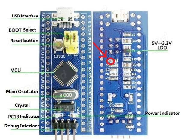
- Pin B2.jpg (52.32 KiB) Viewed 2343 times
However, we included the F macro (that really doesn’t do anything), but in this case it sounds like it causes some problems
Thanks to all they have contributed in this post.
Only a problem:
It doesn’t work:
Serial.println(F(“Using Adafruit 2.8\” TFT Breakout Board Pinout”)); // I must take off the “F(” and “)”
Serial.println(testRoundRects());// Funtions inside Serial.print
Do you know Why??
Thanks
I have 3.5 inch LCD from mcufriend.com with the same pin-out (for UNO-board, ), but an ILI9327 controller for 400×240 pixel.
I have tested it with the above 8bit- lib , but without success.
I tried it with data-pins d0…d7 on PA0…PA7 and Contol-pins on PBx …
and with data-pins d0…d7 on PB0…PB7 and control-pins on PAx …,
but nothing, only a white screen !!
- mcufriend-3-5-tft-uno-shield.7z
- (201.63 KiB) Downloaded 247 times
- STM32_ILI9327_graphic_01.ino
- (9.01 KiB) Downloaded 144 times
STM32_ILI9327_graphic_01.ino
I still suggest that you edit and run my LCD_ID_readreg.ino sketch. This will confirm your wiring.
The beauty of a Shield and Arduino headers is that the world can have 100% confidence in the wiring and reliable connections.
David.
here is the protocol of your program:
- MCUFRIEND_REG_ID.jpg (110.33 KiB) Viewed 895 times
I would like to verify that you get the same result when you run it on the Maple Mini. (edit the pin #defines in the sketch)
Likewise, please post a link to the Library .CPP file. You only supplied .H and .INO
I could then debug your Library with your sketch on my NUCLEO board. (I just need to edit the write8(), setWriteDir() … macros)
David.
it’s a problem, because serial.print etc doesn’t functions on my maple mini.
Therefore better the programs:
- Adafruit_TFTLCD_8bit_STM32.h
- (5.89 KiB) Downloaded 88 times
If you have problems with Serial.print(), please remove all “F()” macros from the sketch, then it should work.
- protocol_TFT_ILI9327_test.jpg (70.52 KiB) Viewed 385 times
but no info on the serial monitor.
usb is on the mini-USB adapter of the maple mini board.
// maple UNO maple
// port Pin Pin
#define LCD_RST PB15 // A4 28
#define LCD_CS PB14 // A3 29
#define LCD_RS PB5 // A2 17
#define LCD_WR PB4 // A1 18
#define LCD_RD PB3 // A0 19
#define LCD_D0 PA0 // 8 11
#define LCD_D1 PA1 // 9 10
#define LCD_D2 PA2 // 2 9
#define LCD_D3 PA3 // 3 8
#define LCD_D4 PA4 // 4 7
#define LCD_D5 PA5 // 5 6
#define LCD_D6 PA6 // 6 5
#define LCD_D7 PA7 // 7 4
with no conflicts with USB-DP/DM (Pin23/24) and Serial1 RX/TX(Pin15/16 25/26),
but no success.
but no info on the serial monitor.
Alternatively, you attach a USART-USB dongle to any of the 3 USARTs that seem to have 7 sets of hardware pins. (you probably don’t have all 7 on your MCU)
Having got the Serial working, you connect your Shield. And edit the readreg sketch to match your wiring.
Until you can produce a good readreg output, we will not have any confidence in your wiring.
And if you have never used “Serial”, the exercise will be invaluable to you.
David.
It was a good idea:
- LCD_ID_register_Maple_mini.jpg (192.35 KiB) Viewed 576 times
If not, please post the actual #defines that gave the good output.
David.
in the register_id sketch I have this defines:
//-- Arduino UNO or Mega 2560 Plugged as shield

//              maple    UNO   maple

//              port     Pin   Pin

#define LCD_CS  PB14  // A3    29

#define LCD_RS  PB5   // A2    17

#define LCD_RST PB15  // A4    28

#define LCD_WR  PB4   // A1    18

#define LCD_RD  PB3   // A0    19
#define LCD_D0 PA0 // 8 11
#define LCD_D1 PA1 // 9 10
#define LCD_D2 PA2 // 2 9
#define LCD_D3 PA3 // 3 8
#define LCD_D4 PA4 // 4 7
#define LCD_D5 PA5 // 5 6
#define LCD_D6 PA6 // 6 5
#define LCD_D7 PA7 // 7 4
The reading of this register is not implemented in my version, that’s why you get as ID the value 0.
You should try to force the ID as being the value 0x9325, and use this value when calling begin() in your sketch.
Then add this conditional block:
#elif defined(__STM32F1__) && defined(ARDUINO_MAPLE_MINI) // Uno Shield on MAPLE_MINI board

#warning Uno Shield on MAPLE_MINI for MAUSI_MICK

// be wise to clear all four mode bits properly.

#define GROUP_MODE(port, reg, mask, val)  {port->regs->reg = (port->regs->reg & ~(mask)) | ((mask)&(val)); }

#define GP_OUT(port, reg, mask)           GROUP_MODE(port, reg, mask, 0x33333333)

#define GP_INP(port, reg, mask)           GROUP_MODE(port, reg, mask, 0x44444444)
#define RD_PORT GPIOB
#define RD_PIN 3
#define WR_PORT GPIOB
#define WR_PIN 4
#define CD_PORT GPIOB
#define CD_PIN 5
#define CS_PORT GPIOB
#define CS_PIN 14
#define RESET_PORT GPIOB
#define RESET_PIN 15
// configure macros for the data pins
#define write_8(d) { GPIOA->regs->BSRR = 0x00FF << 16; GPIOA->regs->BSRR = (d) & 0xFF; }
#define read_8() (GPIOA->regs->IDR & 0xFF)
// PA7 ..PA0
#define setWriteDir() {GP_OUT(GPIOA, CRL, 0xFFFFFFFF); }
#define setReadDir() {GP_INP(GPIOA, CRL, 0xFFFFFFFF); }
#define write8(x) { write_8(x); WR_ACTIVE; WR_STROBE; }
#define write16(x) { uint8_t h = (x)>>8, l = x; write8(h); write8(l); }
#define READ_8(dst) { RD_STROBE; RD_ACTIVE; RD_ACTIVE; RD_ACTIVE; RD_ACTIVE; RD_ACTIVE; dst = read_8(); RD_IDLE; }
#define READ_16(dst) { uint8_t hi; READ_8(hi); READ_8(dst); dst |= (hi << 8); }
#define PIN_HIGH(port, pin) (port)->regs->BSRR = (1<<(pin))
//#define PIN_LOW(port, pin) (port)->regs->BSRR = (1<<((pin)+16))
#define PIN_LOW(port, pin) (port)->regs->ODR &= ~(1<<(pin))
// ######### changed the PIN_OUTPUT() macro ###############################################
#define PIN_OUTPUT(port, pin) gpio_set_mode(port, pin, GPIO_OUTPUT_PP)   //50MHz push-pull only 0-7

#define PIN_INPUT(port, pin)  gpio_set_mode(port, pin, GPIO_INPUT_FLOATING)   //digital input
// ######################################################################################
is the 2.9.1 the last version?
I have installed it … /hardware …/STM32F1/lib…/MCU…_kbv
But I have problems compiling the sketch , a lot of errors !
The IDE should install the Library from the ZIP into your regular Arduino libraries not into STM32.
The Orange output is basically Warnings. It should compile ok. I use v1.6.12 IDE and the ARM tools are 4.8.3-2014q1
I will post you a different PIN_OUTPUT() macro which should support the CRH register but without the Warnings.
David.
#define PIN_OUTPUT(port, pin) gpio_set_mode(port, pin, GPIO_OUTPUT_PP) //50MHz push-pull only 0-7
#define PIN_INPUT(port, pin) gpio_set_mode(port, pin, GPIO_INPUT_FLOATING) //digital input
I changed the lib and modified
The address for TFT_CS, TFT_RD … in the sketch.
the errors:
- Error_MCUFRIENDS_graphictest.ino
- (34.3 KiB) Downloaded 72 times
My apologies. I tested STM32 with my private sketch and not the example from the library.
Yes, sure enough, STM32 barfs on icons.c i.e. a C file
My private version of icons.c has:
#if defined(__STM32F1__)

#define PROGMEM

#else

#include <Arduino.h>

#endif
Incidentally, the ILI9327 is VERY different to the 9325, 9341, 8347, ….
User applications can work with different makes, models without any changes (except for Width and Height)
However the “Manufacturer commands” vary greatly. But as a general rule, you only use these commands at the start of an App. In fact, most displays will start up by themselves without the User touching any Manufacturer commands.
The older non-MIPI controllers like the ILI9325 are vastly different in registers, commands, initialisation, …
If you look at my Repo, you will see that there are minor differences for reading GRAM, setting orientation for MIPI controllers. i.e. “compliant” is not a magic bullet.
In practice, most Apps will only use one particular orientation and probably never read GRAM or even registers.
That is why UTFT is so effective. (and easy to add a new controller)
My Repo is due for a significant “tidy up” and a proper new Release.
If you strip out the conditional code, the basic readGRAM(), drawPixel(), setWindow(), setRotation(), vertScroll() … are fairly simple.
Maintaining separate files for 25 controllers would be a nightmare.
OTOH, if you only possess a single controller, you don’t need any conditional code.
David.
But, again, which initial settings of the alternatives (9341, 932x) are the best to use for 9327? Is any initial register setting needed at all?
Or is the 9327 a MIPI compliant controller which does not need any init sequence?
ILI9327 is MIPI compliant 240×432 controller.
But it does have a few problems when you use PORTRAIT_REV or LANDSCAPE_REV with a 240×400 panel.
You can alter the Manufacturer registers to suit your Panel. Ilitek produce App Notes with initialisations for different Panels.
I feel really stupid. I was trying to run your library with an ILI9341. And had not looked closely at the “Adafruit” code.
It is reading the ID wrong. It is initialising wrong.
So I plugged in an ILI9325 Shield. Worked first time !!
David.
p.s. it is attempting identify a HX8357D correctly, but this code is wrong too. Where did you get your original code from?
It contains:
uint16_t readReg(uint8_t r)
Sure, your right.
But if you have a closer look, you will notice that this function is used only in one place in the original code, and at that place the return value of this function is compared with a 16 bit value.
So why to have 32 bits return value of readReg() if only 16 bits are used?
This I call code transparency and optimization.
Anyway, in your code you are using functions with return values of 24 and 40 bit width, too.
This, although it may be necessary, but is also not quite “usual” and conforming to any standard, isn’t it?
I don’t want to be picky, just to point out that one adapt the software to the actual needs. This is the basis for evolution ![]()
I would be more than happy if you would send me some PRs to fix some bugs or suggest improvements for the lib a forked and adapted from Adafruit.
Btw, I really appreciate your work with MCUFRIEND_kbv lib, but I wanted to keep being somehow “compliant” with original Adafruit lib.
now I have only the problem by the compile to find the penguin in the icons.ino:
undefined reference to `penguin’
excuse me, where is the connection in the source to icons.ino ?
I tested it with ILI9325 and changed also your .cpp file :
if ((id == 0x9325) || (id == 0x9327) || (id == 0x9328)) {
driver = ID_932X;
…
but no success.
But I don’t know, if I have to set TFT_DATA_NIBBLE to 0 or 8 ??
and if I have to take fast bit toggling in the .h file
If you compare the public readID() from the two libraries that I linked to, you see why you would not identify the ILI9341, ILI9327, HX8357-D
I also see why begin(0x9341) does not get very far !
There are several approaches for a TFT library:
1. individual library for each controller and interface (and possibly each platform)
2. common code with conditional modules e.g. UTFT
3. identify ID. Implement differences at runtime. e.g. Adafruit_TFTLCD, MCUFRIEND_kbv, …
4. Only identify ID. Build unique ID class with a Template. e.g. u8glib
(1) is a maintenance nightmare
(2) works ok. slow, limited functionality. wastes a lot of Flash memory on a Uno. Fine for Mega, Due, …
(3) wastes a lot of Flash memory on a Uno. Fine for Mega, Due, …
(4) relies on the punter identifying the controller.
I am happy to help with your questions. I suggest that you think through your design strategy.
The Adafruit started with HX8347 and ILI9325. The others have grown. Do you want to keep the HX8347 ?
David.
thanks for your comment, now I realized the mistake I made.
I just corrected the readID function by replacing the “readReg()” by “readReg32()” in the github repo.
I have chosen the first strategy (the nightmare
@mausi_mick
Sorry, but it seems that the Adafruit lib (so as mine) is not configured to read out the ID for 9327 controller yet.
And even if it could, it seems that some more information is missing how to initialize it.
As I don’t have such a board, it would be your task to figure out what is needed to configure the chip (ask David?).
Once you have that information, I could implement it in my lib.
Btw, the data nibble should be 0 if you use the lower 8 bits (as indicated in the source code), otherwise 1.
For the first try I would use the slower method (digitalWrite). If that works, then you could try the faster method.
Please pay attention to the reset line! It is crucial that the controller gets a reset at the beginning!
Have you looked at UTFT?
It has a specific initlcd() and a setxy() for each controller. Stored on separate disk files.
And an array of sizes, interfaces for each “model”.
You can add a new controller or a new interface very easily.
You don’t even need to know too much about the initlcd() sequences.
As long as you can draw in Portrait mode, any transformations are handled in Software. e.g. LANDSCAPE
Actually, Adafruit_TFTLCD does some transformations in software. When EVERY controller is capable of drawing in hardware.
Adafruit_TFTLCD takes advantage of C++ heritability etc. e.g. graphics in Adafruit_GFX.h, printing in Print.h
And has a consistent intuitive set of method()s. UTFT is a dog’s breakfast.
If you are intending to produce separate libraries, you could do one for the (almost obsolete) ILI9325.
And concentrate standard methods for MIPI controllers in anther library. Possibly some different initlcd() i.e. begin() in Adafruit terminology
David.
thanks for your information and your engagement.
Does anyone have a library and example for STM32F103 an this diplay on picture?
Display works with the Arduino Uno and Mcufriend_kbv library.
Does anyone have a library and example for STM32F103 an this diplay on picture?
Display works with the Arduino Uno and Mcufriend_kbv library.
Does anyone have a library and example for STM32F103 an this diplay on picture?
Display works with the Arduino Uno and Mcufriend_kbv library.
I have one of these but it is 3.95″ – never tried it yet. I hope to get it working with help of this thread
There are some discussions on forums that say it would have ili9488
I installed the Maple drivers via the Batch File in the Installation Folder.
The Bootloader would say that it had run but then whinge that it could not reset (or something).
So I changed the Linker file from ld/Flash.ld to ld/jtag.ld to make it run at 0x800000.
Attached the STLink from a NUCLEO board to the Maple SWD pins.
And upload/debug with Rowley.
Is the regular Maple bootloader supposed to be flaky? (I am using Win7-32 on a Laptop)
Should I install the “replacement” Bootloader? Does that work ok?
It is handy to debug via Rowley/STLink. But I would prefer to use a bootloader for regular sketches.
Oh, MCUFRIEND_kbv works on the IteadMaple.
David.
I have an iTeadMaple but I can’t recall the last time I updated the bootloader, as I don’t use that board very much.
Note. DFU often displays an error after the upload is complete. This is a problem with DFU and not the bootloader.
The same thing happens when I use dfu-util to upload to the STM32F4 using its own built in hardware USB DFU bootloader, and I also get the same error using other people’s bootloaders (like the BlackMagic Probe dfu updater)
Can help me someone with wiring?
I have mcufriend 2,4″ TFT which identifiers like 0x1010
LCD D0-D7 is connected to PB0-PB7
LCD_RD – PA4
LCD_WR – PA5
LCD_RS – PA6
LCD_CS – PA7
LCD_RST – PA8
I use Adafruit_TFTLCD_8bit_STM32 from steve strong.
graphic test prints data to serial console and LCD is flickering but nothing is shown.
LCD is good I tested it on arduino uno and it works (not touch screen because I dont have time to calibrate it).
Please use this sketch from David (with adapted wiring) and post here the resulted serial monitor log.
Be aware that PB4 may be reserved for debug port if you upload via SWI or serial 1 (PA9/10).
For upload via USB DFU get the latest commit from the repository, in particular https://github.com/rogerclarkmelbourne/ … boards.txt.
Also, post here the header file adapted to your wiring.
I change initialization sequence but display still only flickering. On next try I will check wiring again and whole 9325 code, still hope than I miss something.
#define TFT_CNTRL_PORT GPIOB
#define LCD_RD PB3
#define LCD_WR PB4
#define LCD_RS PB5
#define LCD_CS PB6
#define LCD_RST PB7
#define TFT_DATA_PORT GPIOA
#define LCD_D0 PA0
#define LCD_D1 PA1
#define LCD_D2 PA2
#define LCD_D3 PA3
#define LCD_D4 PA4
#define LCD_D5 PA5
#define LCD_D6 PA6
#define LCD_D7 PA7
and tested three different initialization sequences for older versions 9325 and still no luck with it. any suggestions someone?
Adafruit_TFTLCD_8bit_STM32.hAdafruit_TFTLCD_8bit_STM32.hFor example, TFT_RD_MASK should be BIT8 if you use PB8, TFT_WR_MASK is BIT9 if you use PB9 and so on (BITX for PBX).
For example, TFT_RD_MASK should be BIT8 if you use PB8, TFT_WR_MASK is BIT9 if you use PB9 and so on (BITX for PBX).
I can read id of LCD but now is showing nothing.
Is some way to check whole board? I can check pins separately by connecting power on them but if is some other way..
I have trouble with a TFT Display: Its that:
“Elegoo 2.8” TFT Touch Screen – ILI9341″
https://www.elegoo.com/product/elegoo-u … ch-screen/
The display has 28 Pins. 8 Pins are marked as LCD_D0 to LCD_D7. Then there is LCD_RST, LCD_CS, LCD_RS, LCD_WR and LCD_RD.
3 Pins are for the power 5V, 3.3V and GND. 8 Pins seems to be unused, and there are 4 Pins for and SD Card (SD_SS, SD_DI, SD_DO and SD_SCK)
On an Uno, the display works with the elegoo lib, which is in fact the Adafruit TFT/GFX Lib.
The MCUFRIEND_kbv (Version 2.95? , there is a #define MCUFRIEND_KBV_H_ 295 in the code) also works fine.
When I put the shield on the Uno, I get:
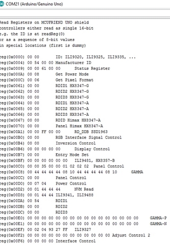
Read Registers on MCUFRIEND UNO shield
controllers either read as single 16-bit
e.g. the ID is at readReg(0)
or as a sequence of 8-bit values
in special locations (first is dummy)
reg(0x0000) 00 00 ID: ILI9320, ILI9325, ILI9335, …
reg(0x0004) 00 00 00 00 Manufacturer ID
reg(0x0009) 00 00 61 00 00 Status Register
reg(0x000A) 00 08 Get Power Mode
reg(0x000C) 00 06 Get Pixel Format
reg(0x0061) 00 00 RDID1 HX8347-G
reg(0x0062) 00 00 RDID2 HX8347-G
reg(0x0063) 00 00 RDID3 HX8347-G
reg(0x0064) 00 00 RDID1 HX8347-A
reg(0x0065) 00 00 RDID2 HX8347-A
reg(0x0066) 00 00 RDID3 HX8347-A
reg(0x0067) 00 00 RDID Himax HX8347-A
reg(0x0070) 00 00 Panel Himax HX8347-A
reg(0x00A1) 00 00 00 00 00 RD_DDB SSD1963
reg(0x00B0) 00 00 RGB Interface Signal Control
reg(0x00B4) 00 02 Inversion Control
reg(0x00B6) 00 0A 82 27 04 Display Control
reg(0x00B7) 00 06 Entry Mode Set
reg(0x00BF) 00 00 00 00 00 00 ILI9481, HX8357-B
reg(0x00C0) 00 21 00 00 00 00 00 00 00 Panel Control
reg(0x00C8) 00 00 00 00 00 00 00 00 00 00 00 00 00 GAMMA
reg(0x00CC) 00 71 Panel Control
reg(0x00D0) 00 00 00 Power Control
reg(0x00D2) 00 00 00 03 03 NVM Read
reg(0x00D3) 00 00 93 41 ILI9341, ILI9488
reg(0x00D4) 00 00 00 00 Novatek ID
reg(0x00DA) 00 00 RDID1
reg(0x00DB) 00 00 RDID2
reg(0x00DC) 00 00 RDID3
reg(0x00E0) 00 0F 16 14 0A 0D 06 43 75 33 06 0E 00 0C 09 08 GAMMA-P
reg(0x00E1) 00 08 2B 2D 04 10 04 3E 24 4E 04 0F 0E 35 38 0F GAMMA-N
reg(0x00EF) 00 03 80 02 02 02 ILI9327
reg(0x00F2) 00 02 02 02 02 02 02 02 02 02 02 02 Adjust Control 2
reg(0x00F6) 00 01 00 00 Interface Control
I installed STM32Arduino and the board NUCLEO-F103RB.
When I put the display shield on the Nucleo Board, I got:
Read Registers on MCUFRIEND UNO shield
controllers either read as single 16-bit
e.g. the ID is at readReg(0)
or as a sequence of 8-bit values
in special locations (first is dummy)
reg(0x0000) 00 00 ID: ILI9320, ILI9325, ILI9335, …
reg(0x0004) 00 00 00 00 Manufacturer ID
reg(0x0009) 00 00 61 00 00 Status Register
reg(0x000A) 00 08 Get Power Mode
reg(0x000C) 00 06 Get Pixel Format
reg(0x0061) 00 00 RDID1 HX8347-G
reg(0x0062) 00 00 RDID2 HX8347-G
reg(0x0063) 00 00 RDID3 HX8347-G
reg(0x0064) 00 00 RDID1 HX8347-A
reg(0x0065) 00 00 RDID2 HX8347-A
reg(0x0066) 00 00 RDID3 HX8347-A
reg(0x0067) 00 00 RDID Himax HX8347-A
reg(0x0070) 00 00 Panel Himax HX8347-A
reg(0x00A1) 00 00 00 00 00 RD_DDB SSD1963
reg(0x00B0) 00 00 RGB Interface Signal Control
reg(0x00B4) 00 02 Inversion Control
reg(0x00B6) 00 0A 82 27 04 Display Control
reg(0x00B7) 00 06 Entry Mode Set
reg(0x00BF) 00 00 00 00 00 00 ILI9481, HX8357-B
reg(0x00C0) 00 21 00 00 00 00 00 00 00 Panel Control
reg(0x00C8) 00 00 00 00 00 00 00 00 00 00 00 00 00 GAMMA
reg(0x00CC) 00 71 Panel Control
reg(0x00D0) 00 00 00 Power Control
reg(0x00D2) 00 00 00 03 03 NVM Read
reg(0x00D3) 00 00 93 41 ILI9341, ILI9488
reg(0x00D4) 00 00 00 00 Novatek ID
reg(0x00DA) 00 00 RDID1
reg(0x00DB) 00 00 RDID2
reg(0x00DC) 00 00 RDID3
reg(0x00E0) 00 0F 16 14 0A 0D 06 43 75 33 06 0E 00 0C 09 08 GAMMA-P
reg(0x00E1) 00 08 2B 2D 04 10 04 3E 24 4E 04 0F 0E 35 38 0F GAMMA-N
reg(0x00EF) 00 03 80 02 02 02 ILI9327
reg(0x00F2) 00 02 02 02 02 02 02 02 02 02 02 02 Adjust Control 2
reg(0x00F6) 00 01 00 00 Interface Control
But I totally lost with any other code for the display on STM32. Not a single sketch compiles without errors. (Except the ReadRegisters above)
The example graphictest_kbv from MCUFRIEND gives:
C:\Users\[..]\MCUFRIEND_kbv\utility/mcufriend_shield.h:422:2: error: #error MCU unsupported
#error MCU unsupported
All othe libaries I tried, complain of something in libmaple:
Example:
C:\Users\[..]\Arduino\libraries\Adafruit_ILI9341_8bit_STM\Adafruit_ILI9341_8bit_STM.cpp:9:26: fatal error: libmaple/dma.h: No such file or directory
Now I am clueless. What I’am doing so wrong?
What is the problem with MCUFRIEND_kbv ?
I have just run graphictest_kbv with “Nucleo F103RB” from STM32F1xx Cores by ST-Microelectronics.
And with “STM Nucleo F103RB (STLink)” from the MapleCore by RogerClark et al.
MCUFRIEND_kbv looks for defined(ARDUINO_STM_NUCLEO_F103RB) || defined(ARDUINO_NUCLEO_F103RB)
[..] You need v2.9.5-Beta for the cores from ST-Microelectronics
But the v2.9.4 Release should work with the MapleCore.
If you describe your problems, I can probably sort you out.
David.
Go to the Library Manager. Search for MCUFRIEND_kbv library. The Manager will tell you which version you have installed. e.g. 2.9.4
The Library Manager only installs a Release.
If you want to use a Beta version, you download the ZIP from GitHub. Then install from ZIP.
If I can ever buy a shield with a HX8357-B controller, I will test it and post a new Release.
Buying shields from Ebay is a lottery. You do not know what controller is mounted until the packet arrives. The Ebay Vendors have no idea what they are selling.
David.
Has there been any updates?
Has anyone got this display working in the arduino ide?
This will confirm your wiring. Post the list of #defines from the readreg sketch.
And quite honestly, every controller supported by MCUFRIEND_kbv should work. e.g. ILI9327
I will write the appropriate SPECIAL to match your #defines.
David.
Go to the Library Manager. Search for MCUFRIEND_kbv library. The Manager will tell you which version you have installed. e.g. 2.9.4
The Library Manager only installs a Release.
If you want to use a Beta version, you download the ZIP from GitHub. Then install from ZIP.
David.
u used davids sketch and an arduino nano
reg(0x0000) 44 44 ID: ILI9320, ILI9325, ILI9335, …
reg(0x0004) 00 54 00 00 Manufacturer ID
reg(0x0009) 00 00 61 00 00 Status Register
reg(0x000A) 00 08 Get Power Mode
reg(0x000C) 00 06 Get Pixel Format
reg(0x0061) 06 06 RDID1 HX8347-G
reg(0x0062) 06 06 RDID2 HX8347-G
reg(0x0063) 06 06 RDID3 HX8347-G
reg(0x0064) 06 06 RDID1 HX8347-A
reg(0x0065) 06 06 RDID2 HX8347-A
reg(0x0066) 06 06 RDID3 HX8347-A
reg(0x0067) 06 06 RDID Himax HX8347-A
reg(0x0070) 06 06 Panel Himax HX8347-A
reg(0x00A1) 00 00 FF 00 00 RD_DDB SSD1963
reg(0x00B0) 00 00 RGB Interface Signal Control
reg(0x00B4) 00 00 Inversion Control
reg(0x00B6) 00 00 00 00 00 Display Control
reg(0x00B7) 00 00 Entry Mode Set
reg(0x00BF) 00 00 00 00 00 00 ILI9481, HX8357-B
reg(0x00C0) 00 00 35 00 00 01 02 02 02 Panel Control
reg(0x00C8) 02 44 44 44 44 08 10 44 44 44 44 08 10 GAMMA
reg(0x00CC) 10 10 Panel Control
reg(0x00D0) 10 07 04 Power Control
reg(0x00D2) 04 01 44 44 44 NVM Read
reg(0x00D3) 44 01 44 44 ILI9341, ILI9488
reg(0x00D4) 44 01 44 44 Novatek ID
reg(0x00DA) 00 54 RDID1
reg(0x00DB) 00 00 RDID2
reg(0x00DC) 00 00 RDID3
reg(0x00E0) 00 00 00 00 00 00 00 00 00 00 00 00 00 00 00 00 GAMMA-P
reg(0x00E1) 00 00 00 00 00 00 00 00 00 00 00 00 00 00 00 00 GAMMA-N
reg(0x00EF) 00 02 04 93 27 FF ILI9327
reg(0x00F2) FF FF FF FF FF FF FF FF FF FF FF FF Adjust Control 2
reg(0x00F6) FF FF FF FF Interface Control
So we need the Davids sketch output using your STM32 board and your display.
Read Registers on MCUFRIEND UNO shield
controllers either read as single 16-bit
e.g. the ID is at readReg(0)
or as a sequence of 8-bit values
in special locations (first is dummy)
reg(0x0000) 80 80 ID: ILI9320, ILI9325, ILI9335, …
reg(0x0004) 84 54 00 00 Manufacturer ID
reg(0x0009) 89 89 89 89 89 Status Register
reg(0x000A) 8A 8A Get Power Mode
reg(0x000C) 8C 8C Get Pixel Format
reg(0x0061) 06 06 RDID1 HX8347-G
reg(0x0062) 06 86 RDID2 HX8347-G
reg(0x0063) 06 06 RDID3 HX8347-G
reg(0x0064) 06 86 RDID1 HX8347-A
reg(0x0065) 06 86 RDID2 HX8347-A
reg(0x0066) 06 06 RDID3 HX8347-A
reg(0x0067) 06 06 RDID Himax HX8347-A
reg(0x0070) 06 06 Panel Himax HX8347-A
reg(0x00A1) 00 00 FF 00 00 RD_DDB SSD1963
reg(0x00B0) 00 00 RGB Interface Signal Control
reg(0x00B4) 00 00 Inversion Control
reg(0x00B6) 00 00 00 00 00 Display Control
reg(0x00B7) 00 00 Entry Mode Set
reg(0x00BF) 00 00 00 00 00 00 ILI9481, HX8357-B
reg(0x00C0) 00 00 35 00 00 01 02 02 02 Panel Control
reg(0x00C8) 02 44 44 44 44 08 10 44 44 44 44 08 10 GAMMA
reg(0x00CC) 10 10 Panel Control
reg(0x00D0) 10 10 10 Power Control
reg(0x00D2) 10 01 44 44 44 NVM Read
reg(0x00D3) 44 01 44 44 ILI9341, ILI9488
reg(0x00D4) 44 01 44 44 Novatek ID
reg(0x00DA) 00 50 RDID1
reg(0x00DB) 00 00 RDID2
reg(0x00DC) 00 00 RDID3
reg(0x00E0) 00 00 00 00 00 00 00 00 00 00 00 00 00 00 00 00 GAMMA-P
reg(0x00E1) 00 00 00 00 00 00 00 00 00 00 00 00 00 00 00 00 GAMMA-N
reg(0x00EF) 00 02 04 93 27 FF ILI9327
reg(0x00F2) FF FF FF FF FF FF FF FF FF FF FF FF Adjust Control 2
reg(0x00F6) FF FF FF FF Interface Control
Double posting regarding the same issue should be avoided.
//-- Arduino DUE_ELECHOUSE_SHIELD

#define LCD_RST 33 //PC1

#define LCD_CS 31 //PA7

#define LCD_RS 22 //PB26

#define LCD_WR 23 //PA14

#define LCD_RD 24 //PA15
#define LCD_D0 34 //PC2

#define LCD_D1 35

#define LCD_D2 36

#define LCD_D3 37

#define LCD_D4 38

#define LCD_D5 39

#define LCD_D6 40

#define LCD_D7 41 //PC9
#define LCD_RST PB11
#define LCD_CS PB12
#define LCD_RS PB13
#define LCD_WR PB14
#define LCD_RD PB15
#define LCD_D0 PA0
#define LCD_D1 PA1
#define LCD_D2 PA2
#define LCD_D3 PA3
#define LCD_D4 PA4
#define LCD_D5 PA5
#define LCD_D6 PA6
#define LCD_D7 PA7
whith this result
8-bit values
in special locations (first is dummy)
reg(0x0000) FF FF ID: ILI9320, ILI9325, ILI9335, …
reg(0x0004) 00 54 00 00 Manufacturer ID
reg(0x0009) 00 00 68 82 00 Status Register
reg(0x000A) 00 40 Get Power Mode
reg(0x000C) 00 06 Get Pixel Format
reg(0x0061) 06 06 RDID1 HX8347-G
reg(0x0062) 06 06 RDID2 HX8347-G
reg(0x0063) 06 06 RDID3 HX8347-G
reg(0x0064) 06 06 RDID1 HX8347-A
reg(0x0065) 06 06 RDID2 HX8347-A
reg(0x0066) 06 06 RDID3 HX8347-A
reg(0x0067) 06 06 RDID Himax HX8347-A
reg(0x0070) 06 06 Panel Himax HX8347-A
reg(0x00A1) 00 00 FF 00 00 RD_DDB SSD1963
reg(0x00B0) 00 00 RGB Interface Signal Control
reg(0x00B4) 00 00 Inversion Control
reg(0x00B6) 00 00 00 00 00 Display Control
reg(0x00B7) 00 00 Entry Mode Set
reg(0x00BF) 00 00 00 00 00 00 ILI9481, HX8357-B
reg(0x00C0) 00 00 35 00 00 01 02 02 02 Panel Control
reg(0x00C8) 02 44 44 44 44 08 10 44 44 44 44 08 10 GAMMA
reg(0x00CC) 10 10 Panel Control
reg(0x00D0) 10 07 04 Power Control
reg(0x00D2) 04 01 44 44 44 NVM Read
reg(0x00D3) 44 01 44 44 ILI9341, ILI9488
reg(0x00D4) 44 01 44 44 Novatek ID
reg(0x00DA) 00 54 RDID1
reg(0x00DB) 00 00 RDID2
reg(0x00DC) 00 00 RDID3
reg(0x00E0) 00 00 00 00 00 00 00 00 00 00 00 00 00 00 00 00 GAMMA-P
reg(0x00E1) 00 00 00 00 00 00 00 00 00 00 00 00 00 00 00 00 GAMMA-N
reg(0x00EF) 00 02 04 93 27 FF ILI9327
reg(0x00F2) FF FF FF FF FF FF FF FF FF FF FF FF Adjust Control 2
reg(0x00F6) FF FF FF FF Interface Control
#define RD_PORT GPIOB

#define RD_PIN  15

#define WR_PORT GPIOB

#define WR_PIN  14

#define CD_PORT GPIOB

#define CD_PIN  13

#define CS_PORT GPIOB

#define CS_PIN  12

#define RESET_PORT GPIOB

#define RESET_PIN  11
I’m wondering if anyone had any success with the ili9327 and either davids or steves library…
I’m sorry if I asked simple questions all this is very confusing to me as im not very experienced with the stm32.
work with Arduino uno r3 with Joao Lopes if forced tft.begin(0x9325);
================================================
ID with https://github.com/prenticedavid/MCUFRIEND_kbv
Read Registers on MCUFRIEND UNO shield

controllers either read as single 16-bit

e.g. the ID is at readReg(0)

or as a sequence of 8-bit values

in special locations (first is dummy)
reg(0x0000) 93 25 ID: ILI9320, ILI9325, ILI9335, ...
reg(0x0004) 00 00 00 00 Manufacturer ID
reg(0x0009) 00 00 00 00 00 Status Register
reg(0x000A) 00 00 Get Power Mode
reg(0x000C) 00 00 Get Pixel Format
reg(0x0061) 00 00 RDID1 HX8347-G
reg(0x0062) 00 00 RDID2 HX8347-G
reg(0x0063) 00 00 RDID3 HX8347-G
reg(0x0064) 00 00 RDID1 HX8347-A
reg(0x0065) 00 00 RDID2 HX8347-A
reg(0x0066) 00 00 RDID3 HX8347-A
reg(0x0067) 00 00 RDID Himax HX8347-A
reg(0x0070) 00 00 Panel Himax HX8347-A
reg(0x00A1) 00 00 00 00 00 RD_DDB SSD1963
reg(0x00B0) 00 00 RGB Interface Signal Control
reg(0x00B4) 00 00 Inversion Control
reg(0x00B6) 00 00 00 00 00 Display Control
reg(0x00B7) 00 00 Entry Mode Set
reg(0x00BF) 00 00 00 00 00 00 ILI9481, HX8357-B
reg(0x00C0) 00 00 00 00 00 00 00 00 00 Panel Control
reg(0x00C8) 00 0A 00 0A 00 0A 00 0A 00 0A 00 0A 00 GAMMA
reg(0x00CC) 00 04 Panel Control
reg(0x00D0) 00 33 00 Power Control
reg(0x00D2) 00 FF 00 FF 00 NVM Read
reg(0x00D3) 00 3F 00 3F ILI9341, ILI9488
reg(0x00D4) 00 6F 00 6F Novatek ID
reg(0x00DA) 00 00 RDID1
reg(0x00DB) 00 00 RDID2
reg(0x00DC) 00 00 RDID3
reg(0x00E0) 00 00 00 00 00 00 00 00 00 00 00 00 00 00 00 00 GAMMA-P
reg(0x00E1) 00 00 00 00 00 00 00 00 00 00 00 00 00 00 00 00 GAMMA-N
reg(0x00EF) 12 31 12 31 12 31 ILI9327
reg(0x00F2) 00 00 00 00 00 00 00 00 00 00 00 00 Adjust Control 2
reg(0x00F6) 00 00 00 00 Interface Control
If you want to use some different scheme, you will have to write your own SPECIAL.
Test your wiring with the LCD_ID_readreg.ino sketch.
If you have verified the wiring, I am happy to help with writing the SPECIAL.
David.
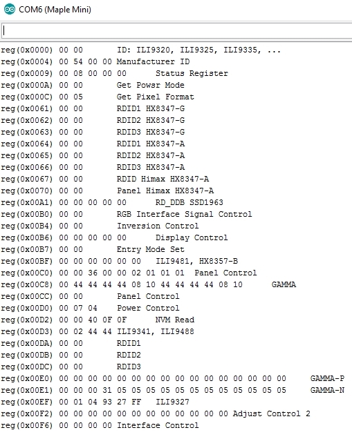
I test LCD_ID_readreg with MapleMini
Read Registers on MCUFRIEND UNO shield

controllers either read as single 16-bit

e.g. the ID is at readReg(0)

or as a sequence of 8-bit values

in special locations (first is dummy)
reg(0x0000) 93 25 ID: ILI9320, ILI9325, ILI9335, ...
reg(0x0004) 00 00 00 00 Manufacturer ID
reg(0x0009) 00 00 00 00 00 Status Register
reg(0x000A) 00 00 Get Power Mode
reg(0x000C) 00 00 Get Pixel Format
reg(0x0061) 00 00 RDID1 HX8347-G
reg(0x0062) 00 00 RDID2 HX8347-G
reg(0x0063) 00 00 RDID3 HX8347-G
reg(0x0064) 00 00 RDID1 HX8347-A
reg(0x0065) 00 00 RDID2 HX8347-A
reg(0x0066) 00 00 RDID3 HX8347-A
reg(0x0067) 00 00 RDID Himax HX8347-A
reg(0x0070) 00 00 Panel Himax HX8347-A
reg(0x00A1) 00 00 00 00 00 RD_DDB SSD1963
reg(0x00B0) 00 00 RGB Interface Signal Control
reg(0x00B4) 00 00 Inversion Control
reg(0x00B6) 00 00 00 00 00 Display Control
reg(0x00B7) 00 00 Entry Mode Set
reg(0x00BF) 00 00 00 00 00 00 ILI9481, HX8357-B
reg(0x00C0) 00 00 00 00 00 00 00 00 00 Panel Control
reg(0x00C8) 00 0A 00 0A 00 0A 00 0A 00 0A 00 0A 00 GAMMA
reg(0x00CC) 00 04 Panel Control
reg(0x00D0) 00 33 00 Power Control
reg(0x00D2) 00 FF 00 FF 00 NVM Read
reg(0x00D3) 00 3F 00 3F ILI9341, ILI9488
reg(0x00D4) 00 6F 00 6F Novatek ID
reg(0x00DA) 00 00 RDID1
reg(0x00DB) 00 00 RDID2
reg(0x00DC) 00 00 RDID3
reg(0x00E0) 00 00 00 00 00 00 00 00 00 00 00 00 00 00 00 00 GAMMA-P
reg(0x00E1) 00 00 00 00 00 00 00 00 00 00 00 00 00 00 00 00 GAMMA-N
reg(0x00EF) 12 31 12 31 12 31 ILI9327
reg(0x00F2) 00 00 00 00 00 00 00 00 00 00 00 00 Adjust Control 2
reg(0x00F6) 00 00 00 00 Interface Control
Your MapleMini has no Arduino headers. It does not even have official Analog pins
If you post the defines that you have used in LCD_ID_readreg, I will know your wiring scheme and that it works! I can post a SPECIAL for you. And you can test it. The MapleMini is supported by both Roger’s MapleCore and the Core from ST.
David.
—————————————————————————————————————
//-- MAPLEMINI Plugged as shield

#define LCD_WR PA1 //10

#define LCD_RD PA0 //11

#define LCD_RST PA8 //27

#define LCD_CS PA3 //8

#define LCD_RS PA2  //9
#define LCD_D0 PB0

#define LCD_D1 PB1

#define LCD_D2 PB2

#define LCD_D3 PB3

#define LCD_D4 PB4

#define LCD_D5 PB5

#define LCD_D6 PB6

#define LCD_D7 PB7
Which changes did you make there beside adapting the pins to your wiring?
What exactly is not working there?
Could you read the ID?
Can you post your code?
connectionPORTB to DATA LCD
//Control pins |RD |WR |RS |CS |RST|
#define TFT_CNTRL_PORT GPIOA
#define TFT_RD PA0
#define TFT_WR PA1
#define TFT_RS PA2
#define TFT_CS PA3
--------------------------------------------
#define TFT_RST PB10-----> connect to PB10???
I most likely will have to change the strategy here since I see many users confronted with the same issue.
Adafruit_TFTLCD_8bit_STM32.hIf you want to use MCUFRIEND_kbv please make these edits:
MCUFRIEND_kbv.h:
#elif defined(ARDUINO_GENERIC_STM32F103C) || defined(ARDUINO_GENERIC_STM32F103V) || defined(ARDUINO_MAPLE_REV3) || defined(ARDUINO_MAPLE_MINI)

MCUFRIEND_kbv(int CS=0, int RS=0, int WR=0, int RD=0, int RST=0);  //dummy arguments
In my lib I use data for ILI9328, which may be different from ILI9325.
Having a look to David’s lib, the 9325 init sequence is there, and it seems that is used for both 9325 and 9328, so you could maybe import to my lib and try it out.
EDIT
Instead of reading the ID, you could set the ID in the sketch fixed to 0x9328, and begin the library with this value.
white screen
Serial output in graphictest_kbv
Serial took 0ms to start

ID = 0x9325
Since you do not have a proper “mating” shield, any special code should be in mcufriend_special.h
I have posted a test_vadim Branch on GitHub. You have to download ZIP and install from ZIP.
David.
I do not test touch, i connect touch like in scheme to analog pins, and test soon.
=================================
mcufriend 0x9325 the same white screen
I would get familiar with the basic TFT and GFX methods first. The existing TouchScreen libraries all have issues with Due, Zero, STM32, Teensy, … generally due to pinMode() and digitalWrite() “optimisations”.
I will publish a bog-standard TouchScreen_kbv version that just uses the Arduino analogRead() and digitalWrite(). It works plenty fast enough on the ARM. And quite honestly, it is not too bad on a Uno.
David.
saleae logic capture arduino uno r3 and maplemini (forced 0x9325 capture) http://dropmefiles.com/wdtzB
only tft.begin(9325) sequence http://dropmefiles.com/p6Rmp
[VadimEL – Tue Jul 04, 2017 8:08 am] –
Iteadmaple cost 33$maplemini(STM32F103CBT6) the same hardware and cost 6$

—————————————————————————————————————
The link to their new page has them listed at 5.80 USD
https://www.itead.cc/development-platfo … maple.html
I bought one about a month ago, shipping time to the US was 12 days.
In slow 48Mhz speed it almost work =)
=======================================
ok some how it start work well on 48Mhz, do not know why О_О
In 72Mhz – white screen after tft.begin(0x9325);
In 48Mhz – screen black after tft.begin(0x9325);
==============================================
I think truble in WriteData(dat);
Maybe it’s in MapleMini registers 72Mhz truble
I would always be happier with a Shield mating with proper Arduino header sockets.
It is electrically reliable and mechanically robust.
I solder a BluePill onto a Chinese Protoshield pcb. Solder Arduino headers. Solder wire links from BluePill to Arduino headers.
It takes a bit of time. I would prefer to buy a ready made Shield Adapter.
And hey-ho. I thought that my IteadMaple was one of the last from a discontinued production. (mine was $10 or so)
It looks as if they have found some more stock. ($5.80 is very good value)
David.
https://github.com/stevstrong/Adafruit_ … 8bit_STM32
It shows the id is ili9341 and it doesn’t work. what is the problem??? how can i solve it???
Make sure that you change the used pins according to your setup using PXY format (PA2, PB14, etc.).
[stevestrong – Mon Jul 10, 2017 2:16 pm] –
Please post here the serial monitor output of this example sketch from David.
Make sure that you change the used pins according to your setup using PXY format (PA2, PB14, etc.).
what do you mean about changing used pins?????
use LCD_ID_readreg

example to read ID of your screen. Change name of pins in example, I use in maple mini
//-- MAPLEMINI Plugged as shield

#define LCD_WR PA1 //10

#define LCD_RD PA0 //11

#define LCD_RST PA8 //27

#define LCD_CS PA3 //8

#define LCD_RS PA2  //9
#define LCD_D0 PB0
#define LCD_D1 PB1
#define LCD_D2 PB2
#define LCD_D3 PB3
#define LCD_D4 PB4
#define LCD_D5 PB5
#define LCD_D6 PB6
#define LCD_D7 PB7
[stevestrong – Mon Jul 10, 2017 2:16 pm] –
Please post here the serial monitor output of this example sketch from David.
Make sure that you change the used pins according to your setup using PXY format (PA2, PB14, etc.).
Read Registers on MCUFRIEND UNO shield

controllers either read as single 16-bit

e.g. the ID is at readReg(0)

or as a sequence of 8-bit values

in special locations (first is dummy)
reg(0x0000) 00 00 ID: ILI9320, ILI9325, ILI9335, …
reg(0x0004) 00 00 00 00 Manufacturer ID
reg(0x0009) 00 00 00 00 00 Status Register
reg(0x000A) 07 70 Get Power Mode
reg(0x000C) 00 00 Get Pixel Format
reg(0x0061) 00 00 RDID1 HX8347-G
reg(0x0062) 00 00 RDID2 HX8347-G
reg(0x0063) 00 00 RDID3 HX8347-G
reg(0x0064) 00 00 RDID1 HX8347-A
reg(0x0065) 00 00 RDID2 HX8347-A
reg(0x0066) 00 00 RDID3 HX8347-A
reg(0x0067) 00 00 RDID Himax HX8347-A
reg(0x0070) 00 00 Panel Himax HX8347-A
reg(0x00A1) 00 00 00 00 00 RD_DDB SSD1963
reg(0x00B0) 00 00 RGB Interface Signal Control
reg(0x00B4) 00 00 Inversion Control
reg(0x00B6) 00 00 00 00 00 Display Control
reg(0x00B7) 00 00 Entry Mode Set
reg(0x00BF) 00 00 00 00 00 00 ILI9481, HX8357-B
reg(0x00C0) 00 00 00 00 00 00 00 00 00 Panel Control
reg(0x00C8) 00 00 00 00 00 00 00 00 00 00 00 00 00 GAMMA
reg(0x00CC) 00 00 Panel Control
reg(0x00D0) 00 00 00 Power Control
reg(0x00D2) 00 00 00 00 00 NVM Read
reg(0x00D3) 00 00 00 00 ILI9341, ILI9488
reg(0x00D4) 00 00 00 00 Novatek ID
reg(0x00DA) 00 00 RDID1
reg(0x00DB) 00 00 RDID2
reg(0x00DC) 00 00 RDID3
reg(0x00E0) 00 00 00 00 00 00 00 00 00 00 00 00 00 00 00 00 GAMMA-P
reg(0x00E1) 00 00 00 00 00 00 00 00 00 00 00 00 00 00 00 00 GAMMA-N
reg(0x00EF) 00 00 00 00 00 00 ILI9327
reg(0x00F2) 00 00 00 00 00 00 00 00 00 00 00 00 Adjust Control 2
reg(0x00F6) 00 00 00 00 Interface Control
is this OK???
[golpesar132 – Mon Jul 10, 2017 8:04 pm] –
is this OK???
No, it is not OK, it seems that your wiring is not correct.
This is what you should get:
reg(0x0000) 93 25 ID: ILI9320, ILI9325, ILI9335, ...
Just one thing has value…
Pay attention to the power supplies, Arduino boards use 5V, the STM boards are mostly using 3.3V.
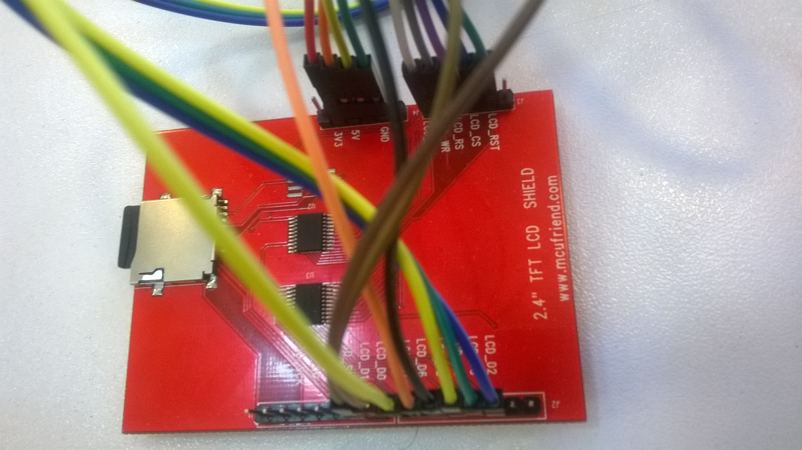
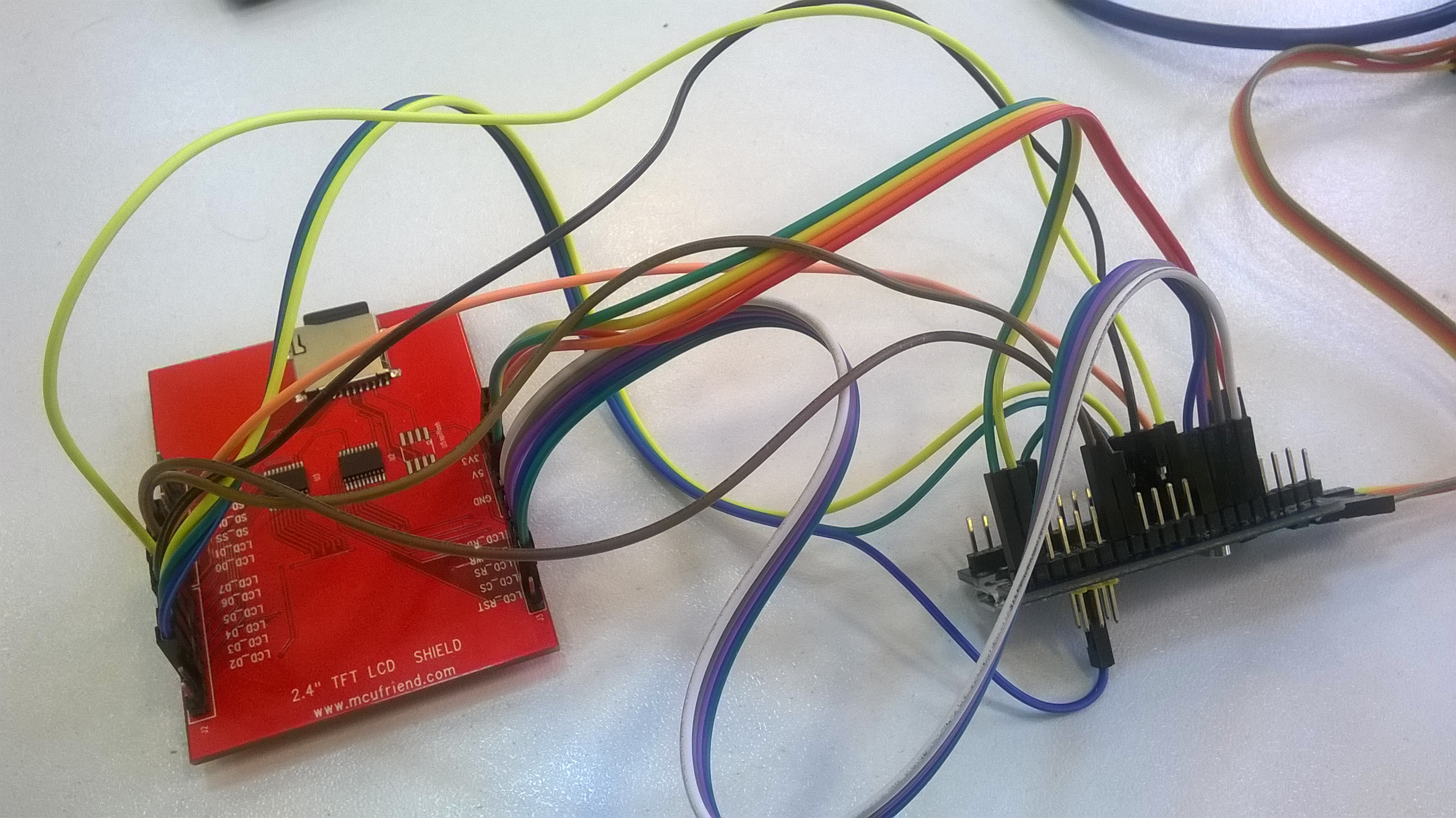
Can you post a picture of your hardware setup, including the wires?
http://shop.aftabrayaneh.com/LCD_Monito … AFTAB.html
this is my hardware :
I uploaded the code on arduino uno and I got this:
Read Registers on MCUFRIEND UNO shield
controllers either read as single 16-bit
e.g. the ID is at readReg(0)
or as a sequence of 8-bit values
in special locations (first is dummy)
reg(0x0000) 93 25 ID: ILI9320, ILI9325, ILI9335, ...
reg(0x0004) 00 00 00 00 Manufacturer ID
reg(0x0009) 00 00 00 00 00 Status Register
reg(0x000A) 00 00 Get Power Mode
reg(0x000C) 00 00 Get Pixel Format
reg(0x0061) 00 00 RDID1 HX8347-G
reg(0x0062) 00 00 RDID2 HX8347-G
reg(0x0063) 00 00 RDID3 HX8347-G
reg(0x0064) 00 00 RDID1 HX8347-A
reg(0x0065) 00 00 RDID2 HX8347-A
reg(0x0066) 00 00 RDID3 HX8347-A
reg(0x0067) 00 00 RDID Himax HX8347-A
reg(0x0070) 00 00 Panel Himax HX8347-A
reg(0x00A1) 00 00 00 00 00 RD_DDB SSD1963
reg(0x00B0) 00 00 RGB Interface Signal Control
reg(0x00B4) 00 00 Inversion Control
reg(0x00B6) 00 00 00 00 00 Display Control
reg(0x00B7) 00 00 Entry Mode Set
reg(0x00BF) 00 00 00 00 00 00 ILI9481, HX8357-B
reg(0x00C0) 00 00 00 00 00 00 00 00 00 Panel Control
reg(0x00C8) 00 00 00 00 00 00 00 00 00 00 00 00 00 GAMMA
reg(0x00CC) 00 00 Panel Control
reg(0x00D0) 00 00 00 Power Control
reg(0x00D2) 00 00 00 00 00 NVM Read
reg(0x00D3) 00 00 00 00 ILI9341, ILI9488
reg(0x00D4) 00 00 00 00 Novatek ID
reg(0x00DA) 00 00 RDID1
reg(0x00DB) 00 00 RDID2
reg(0x00DC) 00 00 RDID3
reg(0x00E0) 00 00 00 00 00 00 00 00 00 00 00 00 00 00 00 00 GAMMA-P
reg(0x00E1) 00 00 00 00 00 00 00 00 00 00 00 00 00 00 00 00 GAMMA-N
reg(0x00EF) 12 31 12 31 12 31 ILI9327
reg(0x00F2) 00 00 00 00 00 00 00 00 00 00 00 00 Adjust Control 2
reg(0x00F6) 00 00 00 00 Interface Control
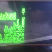
I am happy, i found error in your code =)
After change this
#define WR_STROBE { WR_ACTIVE; WR_IDLE; }
to
#define WR_STROBE { WR_ACTIVE; delay_us(1); WR_IDLE; } //PWLW=TWRL=50ns
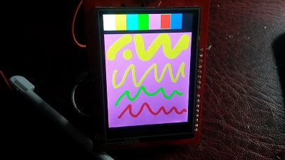
72Mhz with tft – work well. ![]()
![]()
![]()
![]()
==========================
now it’s STM32 and touch screen panel issue. Then i use iwalpola lib touch work….
[golpesar132 – Tue Jul 11, 2017 10:30 am] –
I bought it from this link:
http://shop.aftabrayaneh.com/LCD_Monito … AFTAB.html
I think you forgot to shortcut the R4 which is connected between STM32 and the BOOT1 jumper.
This resistor is 100Kohm so that the PB2 output will not work unless you solder a bridge over this resistor (shortcut).
Please check.
Btw, as initial test, you could enable slow toggling of the control pins by enabling this line (change to “#if 1”): https://github.com/stevstrong/Adafruit_ … TM32.h#L75
If this works then you can go with the high speed version, with “#if 0”.
[VadimEL – Tue Jul 11, 2017 11:57 am] –
David.
I am happy, i found error in your code =)
After change this
#define WR_STROBE { WR_ACTIVE; WR_IDLE; }
to
#define WR_STROBE { WR_ACTIVE; delay_us(1); WR_IDLE; } //PWLW=TWRL=50ns
72Mhz with tft – work well.
==========================
now it’s STM32 and touch screen panel issue. Then i use iwalpola lib touch work….
@Vadim,
You are sampling at 2MHz. Your Saleae can only distinguish 500ns. Even then, it is always safer to sample several times in a pulse.
The whole Write Cycle must be longer than 50ns. You would need to sample at 100MHz or so.
The STM32F103 is not very fast at GPIO driving. The STM32F4xx and even STM32L4xx are much faster.
I have never attempted to use a Saleae on a parallel interface. It is not fast enough.
However, I do use the Saleae on an SPI interface. I just have to slow the SCK down to 8MHz and 24MHz sampling is ok.
I have run STM32F103 on IteadMaple, Nucleo-F103, and two BluePills. One of the BluePills has its data bus on PA0-PA7. And the Write Cycle is as short as the STM32F103 can possibly make it.
If you need to slow things down, you edit the appropriate driver in mcufriend_shield.h or mcufriend_special.h e.g.
#if defined(__STM32F1__) || defined(STM32F103xB)

#define WRITE_DELAY { WR_ACTIVE; WR_ACTIVE; }     //add sufficient macros.

#define READ_DELAY  { RD_ACTIVE; }            //likewise.   read is always much slower
static void init_table16(const void *table, int16_t size)

{

uint16_t *p = (uint16_t *) table;
//в цикле пробегаем весь массив ILI9325_regValues[,] и отправляем поочереди то комманду то данные
while (size > 0)
{
uint16_t cmd = pgm_read_word(p++);//считать комманду
uint16_t d = pgm_read_word(p++);//считать данные
//если ожидание
if (cmd == TFTLCD_DELAY)
{
delay(d);
}
else
{
//delay(1);
CS_ACTIVE; // #define CS_ACTIVE PIN_LOW(CS_PORT, CS_PIN) LCD_CS на 0
//delay(1);
WriteCmd(cmd); //#define WriteCmd(x) { CD_COMMAND; write16(x); } // #define CD_COMMAND PIN_LOW(CD_PORT, CD_PIN) == LCD_RS на 0
//delay(1);
WriteData(d); // #define WriteData(x) { CD_DATA; write16(x); } #define CD_DATA PIN_HIGH(CD_PORT, CD_PIN) == LCD_RS на 1
//delay(1);
CS_IDLE; //CS_IDLE; //1 #define CS_IDLE PIN_HIGH(CS_PORT, CS_PIN) == LCD_CS на 1
//delay(1);
//пауза между (коммандами+данными), чтоб было видно для наглядности
delay(25);
}
size -= 2 * sizeof(int16_t);
}
}
My ILI9325 works fine on BLUEPILL. The Adafruit Tests take 1.39 seconds @ 72MHz
I can do the same Tests in 0.85 seconds on an overclocked Xmega. (the Xmega has got excellent PORT writes)
You appear to have introduced the delays in the tft.begin() call.
The three critical timing areas
1. drawing circles. tft.drawPixel()
2. drawing horiz and vert lines. tft.fillRect()
3. Software Scroll. tft.readGRAM()
David.
[stevestrong – Tue Jul 11, 2017 1:20 pm] –[golpesar132 – Tue Jul 11, 2017 10:30 am] –
I bought it from this link:
http://shop.aftabrayaneh.com/LCD_Monito … AFTAB.htmlI think you forgot to shortcut the R4 which is connected between STM32 and the BOOT1 jumper.
This resistor is 100Kohm so that the PB2 output will not work unless you solder a bridge over this resistor (shortcut).
Please check.Btw, as initial test, you could enable slow toggling of the control pins by enabling this line (change to “#if 1”): https://github.com/stevstrong/Adafruit_ … TM32.h#L75
If this works then you can go with the high speed version, with “#if 0”.
I was unsoldered the R4 and made it short circuit.
I changed that line but it dind’nt work again. my STM32 board can has problem??
Use a LED and connect it to each data and control pin, one after the other.
Make a short test program to toggle these pins.
[stevestrong – Tue Jul 11, 2017 5:54 pm] –
I would start to test each pin, whether it toggles or not.
Use a LED and connect it to each data and control pin, one after the other.
Make a short test program to toggle these pins.
Thank you…
I did it. Pins PA11 PA12 PA15 PB3 PB4 didn’t toggle. I have 2 boards and I test both of them but these pins had problem in both. how can I fix it or change pins in the library????
PA15, PB3 & PB4 are jtag pins after reset. there is a call to disable debug on them.
btw the device data sheet is your friend and also the reference manual later on.
if you’re having issues, try using spi2 on PB12-PB15, it can handle five volt logic levels.
in the library source files, look at the constructor definitions.
stephen
but it still don’t show ant thing on the lcd. why????
Read Registers on MCUFRIEND UNO shield

controllers either read as single 16-bit

e.g. the ID is at readReg(0)

or as a sequence of 8-bit values

in special locations (first is dummy)
reg(0x0000) 93 93	ID: ILI9320, ILI9325, ILI9335, ...

reg(0x0004) 93 93 93 93	Manufacturer ID

reg(0x0009) 93 93 93 93 93	Status Register

reg(0x000A) 93 93	Get Power Mode

reg(0x000C) 93 93	Get Pixel Format

reg(0x0061) 93 93	RDID1 HX8347-G

reg(0x0062) 93 93	RDID2 HX8347-G

reg(0x0063) 93 93	RDID3 HX8347-G

reg(0x0064) 93 93	RDID1 HX8347-A

reg(0x0065) 93 93	RDID2 HX8347-A

reg(0x0066) 93 93	RDID3 HX8347-A

reg(0x0067) 93 93	RDID Himax HX8347-A

reg(0x0070) 93 93	Panel Himax HX8347-A

reg(0x00A1) 93 93 93 93 93	RD_DDB SSD1963

reg(0x00B0) 93 93	RGB Interface Signal Control

reg(0x00B4) 93 93	Inversion Control

reg(0x00B6) 93 93 93 93 93	Display Control

reg(0x00B7) 93 93	Entry Mode Set

reg(0x00BF) 93 93 93 93 93 93	ILI9481, HX8357-B

reg(0x00C0) 93 93 93 93 93 93 93 93 93	Panel Control

reg(0x00C8) 93 93 93 93 93 93 93 93 93 93 93 93 93	GAMMA

reg(0x00CC) 93 93	Panel Control

reg(0x00D0) 93 93 93	Power Control

reg(0x00D2) 93 93 93 93 93	NVM Read

reg(0x00D3) 93 93 93 93	ILI9341, ILI9488

reg(0x00D4) 93 93 93 93	Novatek ID

reg(0x00DA) 93 93	RDID1

reg(0x00DB) 93 93	RDID2

reg(0x00DC) 93 93	RDID3

reg(0x00E0) 93 93 93 93 93 93 93 93 93 93 93 93 93 93 93 93	GAMMA-P

reg(0x00E1) 93 93 93 93 93 93 93 93 93 93 93 93 93 93 93 93	GAMMA-N

reg(0x00EF) 93 93 93 93 93 93	ILI9327

reg(0x00F2) 93 93 93 93 93 93 93 93 93 93 93 93	Adjust Control 2

reg(0x00F6) 93 93 93 93	Interface Control
Paste your LCD_ID_readreg.ino example and make photo of your connection to blue pill. Your CONNECTION IS WRONG
[VadimEL – Mon Jul 17, 2017 8:33 am] –
http://www.stm32duino.com/viewtopic.php … 554#p31543
what???
Read Registers on MCUFRIEND UNO shield

controllers either read as single 16-bit

e.g. the ID is at readReg(0)

or as a sequence of 8-bit values

in special locations (first is dummy)
reg(0x0000) 00 00	ID: ILI9320, ILI9325, ILI9335, ...

reg(0x0004) 00 00 00 00	Manufacturer ID

reg(0x0009) 00 00 00 00 00	Status Register

reg(0x000A) 07 70	Get Power Mode

reg(0x000C) 00 00	Get Pixel Format

reg(0x0061) 00 00	RDID1 HX8347-G

reg(0x0062) 00 00	RDID2 HX8347-G

reg(0x0063) 00 00	RDID3 HX8347-G

reg(0x0064) 00 00	RDID1 HX8347-A

reg(0x0065) 00 00	RDID2 HX8347-A

reg(0x0066) 00 00	RDID3 HX8347-A

reg(0x0067) 00 00	RDID Himax HX8347-A

reg(0x0070) 00 00	Panel Himax HX8347-A

reg(0x00A1) 00 00 00 00 00	RD_DDB SSD1963

reg(0x00B0) 00 00	RGB Interface Signal Control

reg(0x00B4) 00 00	Inversion Control

reg(0x00B6) 00 00 00 00 00	Display Control

reg(0x00B7) 00 00	Entry Mode Set

reg(0x00BF) 00 00 00 00 00 00	ILI9481, HX8357-B

reg(0x00C0) 00 00 00 00 00 00 00 00 00	Panel Control

reg(0x00C8) 00 00 00 00 00 00 00 00 00 00 00 00 00	GAMMA

reg(0x00CC) 00 00	Panel Control

reg(0x00D0) 00 00 00	Power Control

reg(0x00D2) 00 00 00 00 00	NVM Read

reg(0x00D3) 00 00 00 00	ILI9341, ILI9488

reg(0x00D4) 00 00 00 00	Novatek ID

reg(0x00DA) 00 00	RDID1

reg(0x00DB) 00 00	RDID2

reg(0x00DC) 00 00	RDID3

reg(0x00E0) 00 00 00 00 00 00 00 00 00 00 00 00 00 00 00 00	GAMMA-P

reg(0x00E1) 00 00 00 00 00 00 00 00 00 00 00 00 00 00 00 00	GAMMA-N

reg(0x00EF) 00 00 00 00 00 00	ILI9327

reg(0x00F2) 00 00 00 00 00 00 00 00 00 00 00 00	Adjust Control 2

reg(0x00F6) 00 00 00 00	Interface Control
What panel do you have?
is it a Mcufriend Uno Shield?
Or is it a 16-bit 40-pin module?
The Readreg sketch will work with MIPI controllers even if they use a 16-bit data bus. Because all “commands” operate on 8-bit.
If the ILI9325 has got a 16-bit databus, the readReg sketch will be reading the bits 15..8 of reg(0) all the time. You can re-write the readReg sketch if you want for 16-bit reads and writes.
David.
Edit. From your photo, I see that you have a Uno Shield.
I would not expect any reliable results with jumper wires. If you want to use a Shield, solder Arduino headers and links to your STM32.
If your wiring is correct, the readreg sketch should work fine. The display should work fine.
[david.prentice – Mon Jul 17, 2017 8:56 am] –
The MCUFRIEND_kbv library is designed for 8-bit Shields. I know that LCD_RD is plugged into Analog #0 pin. Hence my list of #defines in the Readreg sketch.What panel do you have?
is it a Mcufriend Uno Shield?
Or is it a 16-bit 40-pin module?The Readreg sketch will work with MIPI controllers even if they use a 16-bit data bus. Because all “commands” operate on 8-bit.
If the ILI9325 has got a 16-bit databus, the readReg sketch will be reading the bits 15..8 of reg(0) all the time. You can re-write the readReg sketch if you want for 16-bit reads and writes.David.
I have Mcufriend Uno Shield and it is 8 bits. I send its picture.
I use this code on arduino uno, and that show me the ID is 9325.
afio_cfg_debug_ports(AFIO_DEBUG_NONE);[golpesar132 – Mon Jul 17, 2017 7:21 am] –
thats rigtht. I use below code and all of pins toggle after it.
but it still don’t show ant thing on the lcd. why????
Your information is many times confusing:
– how did the pins toggle if you have not used “afio_cfg_debug_ports(AFIO_DEBUG_SW_ONLY);” before?
Anyway, now that is clear you have an ILI9326, you should be able to use any display lib you want.
The Maple core does.
If MCUFRIEND_kbv is running on the ST core, it enables the PB4 pin.
What is a complete mystery: the Shield returns ID = 0x9325 on a Uno and ID = 0x9326 on MapleMini.
The ILI9326 is a 240×400 with VERY different registers to a 240×320 ILI9325.
From memory, I posted a SPECIAL for golpesar123. So I would expect MCUFRIEND_kbv to work out of the box. Note that you should enable support for ILI9326 and SPFD5420:
#define SUPPORT_9326_5420
Now I have problem with tftbmp example. after I add the following code to the Adafruit_TFTLCD_8bit_STM32.h file:
uint16_t color565(uint8_t r, uint8_t g, uint8_t b)So please set there the LCD pins (and the mask values as well).
Also, don´t forget to allocate the LCD_RST pin, it is important that the LCD get reset.
To be sure that the display works correctly, try a simple example, like drawing a red filled rectangle at the coordinates (50, 100) and see if it works.
Your photo does look like a 240×320. You did say the ID was reported as 0x9325 on a Uno.
But your earlier message showed LCD_readreg.ino with reg(0) returning 0x9326 on the STM32.
It is very straightforward to render a 24-bit BMP from SD card. Most libraries have examples.
Your SD is obviously working fine. It looks as if your tft.setAddrWindow() or tft.pushColors() is not working properly.
Incidentally, I spent some minutes of my life writing a SPECIAL for you.
It would be nice to get some feedback.
David.
Your LCD pin settings in the sketch are not relevant. Only what in the “Adafruit_TFTLCD_8bit_STM32.h” header file is set, is relevant.
So please set there the LCD pins (and the mask values as well).
Also, don´t forget to allocate the LCD_RST pin, it is important that the LCD get reset.
To be sure that the display works correctly, try a simple example, like drawing a red filled rectangle at the coordinates (50, 100) and see if it works.
graphicstest example works well and show all rectangle, circles and ….
it means all of my pins connection is correct.
I would start with a bit of honesty. i.e. do you have a 240×320 ILI9325 or a 240×400 ILI9326.
Your photo does look like a 240×320. You did say the ID was reported as 0x9325 on a Uno.
But your earlier message showed LCD_readreg.ino with reg(0) returning 0x9326 on the STM32.
I don’t know why I got those feedback a couple of times but the LCD reg is 0x9325 and now the LCD show me that.
It is very straightforward to render a 24-bit BMP from SD card. Most libraries have examples.
Your SD is obviously working fine. It looks as if your tft.setAddrWindow() or tft.pushColors() is not working properly.
I think must be right, tft.pushColors() must have some problem. because I think tft.setAddrWindow() but color don’t show correct.
how can i find out that’s true and how can i fix it?
Better said, a function involved by the BMP example, but not involved in graphicstest, is probably the reason.
[stevestrong – Thu Jul 20, 2017 9:29 pm] –
OK, so if graphicstest runs well, setAddressWndow() sould also be ok, then it most probably has to do with the BMP example.Better said, a function involved by the BMP example, but not involved in graphicstest, is probably the reason.
which function for example???
Post a link to the actual library you are using. And either say which example you are using or attach your actual showBMP sketch.
The regular Adafruit graphicstest sketch does not test the pushColors() method. But it is easy enough to write your own test.
But the most important first step is: study the graphicstest sketch carefully. Make notes about any wrong colours or bad shapes.
It is important that Adafruit or any library author gets feedback when there is a problem. However small.
You may want other members to replicate your problem before contacting a big company. It is only polite and they will take more notice of a group of users.
David.
https://github.com/stevstrong/Adafruit_ … 8bit_STM32
and this is my code:
// BMP-loading example specifically for the TFTLCD breakout board.

// If using the Arduino shield, use the tftbmp_shield.pde sketch instead!

// If using an Arduino Mega make sure to use its hardware SPI pins, OR make

// sure the SD library is configured for 'soft' SPI in the file Sd2Card.h.
#include <Adafruit_GFX.h>    // Core graphics library

#include <Adafruit_TFTLCD_8bit_STM32.h> // Hardware-specific library
#include <SD.h>
#include <SPI.h>
// The control pins for the LCD can be assigned to any digital or
// analog pins...but we'll use the analog pins as this allows us to
// double up the pins with the touch screen (see the TFT paint example).
#define LCD_CS PA3 // Chip Select goes to Analog 3
#define LCD_CD PA2 // Command/Data goes to Analog 2
#define LCD_WR PA1 // LCD Write goes to Analog 1
#define LCD_RD PA0 // LCD Read goes to Analog 0
// When using the BREAKOUT BOARD only, use these 8 data lines to the LCD:
// For the Arduino Uno, Duemilanove, Diecimila, etc.:
// D0 connects to digital pin 8 (Notice these are
// D1 connects to digital pin 9 NOT in order!)
// D2 connects to digital pin 2
// D3 connects to digital pin 3
// D4 connects to digital pin 4
// D5 connects to digital pin 5
// D6 connects to digital pin 6
// D7 connects to digital pin 7
// For the Arduino Mega, use digital pins 22 through 29
// (on the 2-row header at the end of the board).
// For Arduino Uno/Duemilanove, etc
// connect the SD card with DI going to pin 11, DO going to pin 12 and SCK going to pin 13 (standard)
// Then pin 10 goes to CS (or whatever you have set up)
#define SD_CS PA4 // Set the chip select line to whatever you use (10 doesnt conflict with the library)
// In the SD card, place 24 bit color BMP files (be sure they are 24-bit!)
// There are examples in the sketch folder
// our TFT wiring
/*
extern Adafruit_TFTLCD_8bit_STM32 TFT;
#define tft TFT
*/
Adafruit_TFTLCD_8bit_STM32 tft;
void setup()
{
afio_cfg_debug_ports(AFIO_DEBUG_NONE);
Serial.begin(115200);
while ( !Serial.isConnected() ) ;
tft.reset();
uint16_t identifier = tft.readID();
if(identifier == 0x9325) {
Serial.println(F("Found ILI9325 LCD driver"));
} else if(identifier == 0x9328) {
Serial.println(F("Found ILI9328 LCD driver"));
} else if(identifier == 0x7575) {
Serial.println(F("Found HX8347G LCD driver"));
} else if(identifier == 0x9341) {
Serial.println(F("Found ILI9341 LCD driver"));
} else if(identifier == 0x8357) {
Serial.println(F("Found HX8357D LCD driver"));
} else {
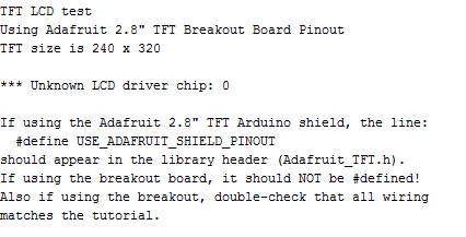
Serial.print(F("Unknown LCD driver chip: "));
Serial.println(identifier, HEX);
Serial.println(F("If using the Adafruit 2.8\" TFT Arduino shield, the line:"));
Serial.println(F(" #define USE_ADAFRUIT_SHIELD_PINOUT"));
Serial.println(F("should appear in the library header (Adafruit_TFT.h)."));
Serial.println(F("If using the breakout board, it should NOT be #defined!"));
Serial.println(F("Also if using the breakout, double-check that all wiring"));
Serial.println(F("matches the tutorial."));
return;
}
tft.begin(identifier);
Serial.print(F("Initializing SD card..."));
if (!SD.begin(SD_CS)) {
Serial.println(F("failed!"));
return;
}
Serial.println(F("OK!"));
bmpDraw("normal.bmp", 0, 0);
delay(1000);
}
void loop()
{
for(int i = 0; i<4; i++) {
tft.setRotation(i);
tft.fillScreen(0);
for(int j=0; j <= 200; j += 50) {
bmpDraw("miniwoof.bmp", j, j);
}
delay(1000);
}
}
// This function opens a Windows Bitmap (BMP) file and
// displays it at the given coordinates. It's sped up
// by reading many pixels worth of data at a time
// (rather than pixel by pixel). Increasing the buffer
// size takes more of the Arduino's precious RAM but
// makes loading a little faster. 20 pixels seems a
// good balance.
#define BUFFPIXEL 20
void bmpDraw(char *filename, int x, int y) {
File bmpFile;
int bmpWidth, bmpHeight; // W+H in pixels
uint8_t bmpDepth; // Bit depth (currently must be 24)
uint32_t bmpImageoffset; // Start of image data in file
uint32_t rowSize; // Not always = bmpWidth; may have padding
uint8_t sdbuffer[3*BUFFPIXEL]; // pixel in buffer (R+G+B per pixel)
uint16_t lcdbuffer[BUFFPIXEL]; // pixel out buffer (16-bit per pixel)
uint8_t buffidx = sizeof(sdbuffer); // Current position in sdbuffer
boolean goodBmp = false; // Set to true on valid header parse
boolean flip = true; // BMP is stored bottom-to-top
int w, h, row, col;
uint8_t r, g, b;
uint32_t pos = 0, startTime = millis();
uint8_t lcdidx = 0;
boolean first = true;
if((x >= tft.width()) || (y >= tft.height())) return;
Serial.println();
Serial.print(F("Loading image '"));
Serial.print(filename);
Serial.println('\'');
// Open requested file on SD card
if ((bmpFile = SD.open(filename)) == NULL) {
Serial.println(F("File not found"));
return;
}
// Parse BMP header
if(read16(bmpFile) == 0x4D42) { // BMP signature
Serial.println(F("File size: ")); Serial.println(read32(bmpFile));
(void)read32(bmpFile); // Read & ignore creator bytes
bmpImageoffset = read32(bmpFile); // Start of image data
Serial.print(F("Image Offset: ")); Serial.println(bmpImageoffset, DEC);
// Read DIB header
Serial.print(F("Header size: ")); Serial.println(read32(bmpFile));
bmpWidth = read32(bmpFile);
bmpHeight = read32(bmpFile);
if(read16(bmpFile) == 1) { // # planes -- must be '1'
bmpDepth = read16(bmpFile); // bits per pixel
Serial.print(F("Bit Depth: ")); Serial.println(bmpDepth);
if((bmpDepth == 24) && (read32(bmpFile) == 0)) { // 0 = uncompressed
goodBmp = true; // Supported BMP format -- proceed!
Serial.print(F("Image size: "));
Serial.print(bmpWidth);
Serial.print('x');
Serial.println(bmpHeight);
// BMP rows are padded (if needed) to 4-byte boundary
rowSize = (bmpWidth * 3 + 3) & ~3;
// If bmpHeight is negative, image is in top-down order.
// This is not canon but has been observed in the wild.
if(bmpHeight < 0) {
bmpHeight = -bmpHeight;
flip = false;
}
// Crop area to be loaded
w = bmpWidth;
h = bmpHeight;
if((x+w-1) >= tft.width()) w = tft.width() - x;
if((y+h-1) >= tft.height()) h = tft.height() - y;
// Set TFT address window to clipped image bounds
tft.setAddrWindow(x, y, x+w-1, y+h-1);
for (row=0; row<h; row++) { // For each scanline...
// Seek to start of scan line. It might seem labor-
// intensive to be doing this on every line, but this
// method covers a lot of gritty details like cropping
// and scanline padding. Also, the seek only takes
// place if the file position actually needs to change
// (avoids a lot of cluster math in SD library).
if(flip) // Bitmap is stored bottom-to-top order (normal BMP)
pos = bmpImageoffset + (bmpHeight - 1 - row) * rowSize;
else // Bitmap is stored top-to-bottom
pos = bmpImageoffset + row * rowSize;
if(bmpFile.position() != pos) { // Need seek?
bmpFile.seek(pos);
buffidx = sizeof(sdbuffer); // Force buffer reload
}
for (col=0; col<w; col++) { // For each column...
// Time to read more pixel data?
if (buffidx >= sizeof(sdbuffer)) { // Indeed
// Push LCD buffer to the display first
if(lcdidx > 0) {
tft.pushColors(lcdbuffer, lcdidx, first);
lcdidx = 0;
first = false;
}
bmpFile.read(sdbuffer, sizeof(sdbuffer));
buffidx = 0; // Set index to beginning
}
// Convert pixel from BMP to TFT format
b = sdbuffer[buffidx++];
g = sdbuffer[buffidx++];
r = sdbuffer[buffidx++];
lcdbuffer[lcdidx++] = tft.color565(r,g,b);
} // end pixel
} // end scanline
// Write any remaining data to LCD
if(lcdidx > 0) {
tft.pushColors(lcdbuffer, lcdidx, first);
}
Serial.print(F("Loaded in "));
Serial.print(millis() - startTime);
Serial.println(" ms");
} // end goodBmp
}
}
bmpFile.close();
if(!goodBmp) Serial.println(F("BMP format not recognized."));
}
// These read 16- and 32-bit types from the SD card file.
// BMP data is stored little-endian, Arduino is little-endian too.
// May need to reverse subscript order if porting elsewhere.
uint16_t read16(File f) {
uint16_t result;
((uint8_t *)&result)[0] = f.read(); // LSB
((uint8_t *)&result)[1] = f.read(); // MSB
return result;
}
uint32_t read32(File f) {
uint32_t result;
((uint8_t *)&result)[0] = f.read(); // LSB
((uint8_t *)&result)[1] = f.read();
((uint8_t *)&result)[2] = f.read();
((uint8_t *)&result)[3] = f.read(); // MSB
return result;
}
Steve’s library only works with the Maple Core. Not with the ST Core.
Anyway, Steve’s library code for pushColors() and setWindow() looks absolutely fine.
Here is a test sketch to prove it (tested on a BluePill):
#include <Adafruit_GFX.h> // Core graphics library
#include <Adafruit_TFTLCD_8bit_STM32.h> // Hardware-specific library
Adafruit_TFTLCD_8bit_STM32 tft;
#define BLACK 0x0000
#define BLUE 0x001F
#define RED 0xF800
#define GREEN 0x07E0
#define CYAN 0x07FF
#define MAGENTA 0xF81F
#define YELLOW 0xFFE0
#define WHITE 0xFFFF
void setup(void) {
afio_cfg_debug_ports(AFIO_DEBUG_NONE);
Serial.begin(9600);
while ( !Serial.isConnected() ) ;
delay(1000);
Serial.println(F("pushColors() test"));
tft.reset();
uint16_t ID = tft.readID();
// ID = 0x9325;
Serial.print(F("ID = 0x"));
Serial.println(ID, HEX);
tft.begin(ID);
tft.fillScreen(BLACK);
tft.setTextColor(YELLOW, BLACK);
tft.setTextSize(2);
}
uint16_t scrollbuf[320]; // Adafruit only does 240x320
// Adafruit can read a block by one pixel at a time
int16_t READGRAM(int16_t x, int16_t y, uint16_t *block, int16_t w, int16_t h)
{
uint16_t *p;
for (int row = 0; row < h; row++) {
p = block + row * w;
for (int col = 0; col < w; col++) {
*p++ = tft.readPixel(x + col, y + row);
}
}
}
void windowScroll(int16_t x, int16_t y, int16_t wid, int16_t ht, int16_t dx, int16_t dy, uint16_t *buf)
{
if (dx) for (int16_t row = 0; row < ht; row++) {
READGRAM(x, y + row, buf, wid, 1);
tft.setAddrWindow(x, y + row, x + wid - 1, y + row);
tft.pushColors(buf + dx, wid - dx, 1);
tft.pushColors(buf + 0, dx, 0);
}
if (dy) for (int16_t col = 0; col < wid; col++) {
READGRAM(x + col, y, buf, 1, ht);
tft.setAddrWindow(x + col, y, x + col, y + ht - 1);
tft.pushColors(buf + dy, ht - dy, 1);
tft.pushColors(buf + 0, dy, 0);
}
}
void loop()
{
int wid = tft.width(), n;
tft.setCursor(0, 200);
tft.print("SOFTWARE SCROLL ");
// scroll a whole width of the screen
n = (wid > 320) ? 320 : wid;
for (int16_t i = n, dx = 4, dy = 0; i > 0; i -= dx) {
windowScroll(0, 200, n, 16, dx, dy, scrollbuf);
}
delay(5000);
}
How can I use MCUFRIEND_kbv library?? How is its wiring??
Install MCUFRIEND_kbv with the Library Manager. Run the examples.
You will see what “SOFTWARE SCROLL” does on the Uno.
The YELLOW text moves across the screen. There should not be any BLUE at all.
I am sure that Steve’s library will work just fine on the STM32.
If Steve’s examples work, so should any other sketches.
MCUFRIEND_kbv works out of the box on a NUCLEO-F103 or NUCLEO-L476
MCUFRIEND_kbv expects the data bus on PA0..PA7. Control signals on PB5..PB9 for a BLUEPILL
I could post you an MCUFRIEND_kbv SPECIAL that matches Steve’s wiring, but I suggest that you continue with Steve’s Library. e.g. re-install.
David.
[stevestrong – Mon Jul 24, 2017 11:32 am] –
I am almost sure that I tested the BMP example reading a file from SD card, but I will check it again.
I am ok with that example. but it is very slow. I want to load it faster like birduino example images, but an image like that is too big and I cant have it on the flash memory of microcontroller. how can I do it faster from sd card?
If you are using the SD card only for reading, then you could use the SdFatEX class (search the SDFat lib for that information, and/or the forum) or use at least a 4kB buffer.
viewtopic.php?f=51&t=2034&p=27982&hilit=sdfatex#p27982
2. parallel processing
– You could (theoretically) use an asynchronous DMA access to send the data to LCD while the new data is read form the SD card.
I don’t have any DMA example which would send parallel data to a GPIO port, but I am interested to see one working with an LCD.
– Another alternative for this is using FreeRTOS – again, I did not use it so far, so cannot provide any support.
– still another potential could be exploited if the SdFat lib would use yield() for the time is waiting for a process to complete…(which is the case for the SDIO lib for F4, but not for SPI)
3. use another chip with more FLASH memory – where you can fit all needed bitmaps in the FLASH.
Btw, it may happen that the F103C8 chip includes 128kB flash instead of the officially specified 64kB.
1. pre-process the BMP files into RAW data e.g. like UTFT utility.
2. set a rectangular window with the correct dimensions.
3. read the raw pixel data from SD with a DMA version of SD.h library.
4. blit the pixel data to the screen. e.g. with pushColors()
5. if you arrange (3) and (4) to run simultaneously, you will effectively fill the screen as fast as your SPI rate from the SD.
6. as Steve has suggested, if you can use a SDIO interface to the SD, it will be faster than SPI.
7. this needs access to all the SD pins and a CPU with SDIO hardware.
I assume that you have got Steve’s library working ok now.
What was the problem?
David.
[david.prentice – Mon Jul 24, 2017 1:07 pm] –
1. pre-process the BMP files into RAW data e.g. like UTFT utility.
how can i do this?? and then how can i read it?
[david.prentice – Mon Jul 24, 2017 1:07 pm] –
I assume that you have got Steve’s library working ok now.
What was the problem?
the color565 wasn’t in the class in that library. just we should use color565() instead of tft.color565().
[david.prentice – Tue May 23, 2017 11:35 am] –
There will be other libraries that might support the LGDP4535.
I plan to add LGDP4535 to the support list.
[stevestrong – Mon Apr 02, 2018 9:36 am] –
I moved the last post here as it seemed to be related to 8 bit lib.
@stevestrong
Thank you.
I added LGDP4535.
But i don’t have this one.
So I can’t test.
I saw a video of a guy suggesting to supply 3.3V everywhere (especially to the 5V pin) and then shorting the in and out pins of the display’s on-board regulator.
Perhaps I’m just wiring it wrong, but I only get a white screen (I’m using PA0..7 as data pins and PB10..12 for control).
Ralph
Have you tested the connections with the example from David?
It make sense to feed the display with 5V because the regulator on blue pill is not strong enough to deliver the necessary current for the background light of the LCD.
Stupid me: I failed to connect the read line (that I don’t use). Oh antenna…. ![]() After I did (connect), it does (work)!
After I did (connect), it does (work)!
Thanks again, Ralph
