I’ve been tinkering with the STM32 on a custom board design for a basic EEPROM dumper/writer. I had things working great on a Teensy 2.0++ with 8 bit registers, but i’m having a heck of a time porting the design over to this STM32.
Here’s a snippet of working code from the Teensy, this just writes a single byte (which is all I need from it):
void write_data(int address, uint8_t data) {

PORTA = address & 0xFF;

PORTB = (address >> 8) & 0xFF;

PORTC = data;
delay(1);
PORTD &= ~(1 << 0); //pull /WR low
delay(2);
PORTD |= (1 << 0); //pull /WR high
}
  PORTA = address & 0xFF;

PORTB = (address >> 8) & 0xFF;

PORTC = data;[flyboy74 – Thu Nov 08, 2018 5:31 am] –
First I notice your 2 bits of code don’t seem to align
You’re right, I had tried removing it before but it hadn’t made a difference. So I thought I’d post the original code I was trying to port, which as you say doesn’t really make sense. So if I just have it as:
GPIOA->regs->ODR = address;
So for STM32F407VET board I use the header “stm32f4xx.h”
as far as I am aware you have the correct struct for the ardunio core
GPIOA->regs->ODR = address;
@ flyboy74 I am using my own board, there are no other devices using up GPIO other than the ones I am using. No extra peripherals here.
About the FSMC, I wasn’t aware of it, but I would assume that would take a complete re-write of my code. I’m not looking for speed, just that it works. Again, if there was a way to do the same thing but with digitalWrite I would be totally fine with that.
  for (int i = datapins[PC0]; i <= datapins[PC7]; i += 1){ //works, but slowly

digitalWrite(i, data & 1);

data = data >> 1;

}
digitalWrite() function simply writes to these registers like u r trying to but it reads the 32bit register then changes the 1 bit then writes the 32bits back to the register.
I have only ever used digitalWrite() on my first few programs that I wrote, I now exclusively use writing directly to the registers to perform all my GPIO operations. I have also written 8bit and 16bit software bit-bang like your trying to do and lately using the HW FSMC peripheral.
Here is my bit-bang code for 16bit writing to a screen on a STM32F407VET. I use the ST header not the ardunio macros
#include "stm32f4xx.h"
#define RS GPIO_ODR_ODR_0
#define WR GPIO_ODR_ODR_1
#define CS GPIO_ODR_ODR_2
#define RST GPIO_ODR_ODR_3
//used for count down in Delay
__IO uint32_t TimmingDelay;
void SysTick_Handler(void)
{
if(TimmingDelay !=0)
{
TimmingDelay --;
}
}
void Delay(__IO uint32_t time)
{
TimmingDelay = time;
while(TimmingDelay !=0);
}
void Pin_setup(void){
//enable port D and E
RCC->AHB1ENR |= RCC_AHB1ENR_GPIODEN | RCC_AHB1ENR_GPIOEEN;
//Port E is used for parallel data pins
//set a port E pins to output.
GPIOE->MODER = 0x55555555;
//set all port E pins to push pull
GPIOE->OTYPER = 0;
//set all port E pins to 100MHz speed
GPIOE->OSPEEDR =0xFFFFFFFF;
//Port D is used for RS, WR, CS, RST
//set needed pins as ouput
GPIOD->MODER |= GPIO_MODER_MODER0_0 | GPIO_MODER_MODER1_0 | GPIO_MODER_MODER2_0 | GPIO_MODER_MODER3_0;
//set needed pin to push pull
GPIOD->OTYPER = 0;
//set needed pins to 100MHZ;
GPIOD->OSPEEDR |= 0x000000FF;
GPIOD->ODR |= RS | WR | CS | RST;
}
void TFT_write_cmd(uint16_t command){
GPIOD->ODR &= ~RS;
GPIOD->ODR &= ~CS;
GPIOD->ODR &= ~WR;
GPIOE->ODR = command;
GPIOD->ODR |= WR;
GPIOD->ODR |= CS;
GPIOD->ODR |= RS;
}
void TFT_write_data(uint16_t data){
GPIOD->ODR &= ~CS;
GPIOD->ODR &= ~WR;
GPIOE->ODR = data;
GPIOD->ODR |= WR;
GPIOD->ODR |= CS;
}
void LCD_setup (void){
//hardware reset
GPIOD->ODR &= ~RST;
Delay(120);
GPIOD->ODR |= RST;
Delay(120);
//software reset
TFT_write_cmd(0x01);
Delay(120);
//sleep out
TFT_write_cmd(0x11);
Delay(120);
//Normal Display Mode On)
TFT_write_cmd(0x13);
//Display On
TFT_write_cmd(0x29);
//CASET (Column Address Set)
TFT_write_cmd(0x2A);
TFT_write_data (0000);
TFT_write_data (320);
//PASET (Page Address Set)
TFT_write_cmd(0x2B);
TFT_write_data (0000);
TFT_write_data (480);
//Exit_idle_mode
TFT_write_cmd(0x38);
//Set_pixel_format RGR565 16 bit
TFT_write_cmd(0x3A);
TFT_write_data(0b01010101);
//RAMWR (Memory Write)
TFT_write_cmd(0x2C);
}
void main(void){
SysTick_Config(SystemCoreClock/1000);
Pin_setup();
LCD_setup();
// Infinite loop
while (1)
{
//write some redish data to the screen
TFT_write_data(0xff00);
}
}
[flyboy74 – Fri Nov 09, 2018 2:06 am] –
What STM32 MCU r u using??digitalWrite() function simply writes to these registers like u r trying to but it reads the 32bit register then changes the 1 bit then writes the 32bits back to the register.
I have only ever used digitalWrite() on my first few programs that I wrote, I now exclusively use writing directly to the registers to perform all my GPIO operations. I have also written 8bit and 16bit software bit-bang like your trying to do and lately using the HW FSMC peripheral.
I’m using the STM32F103R. I don’t really think that’s important here, though, as this issue isn’t specific to what I’m using – it’s just code related.
I’m aware of digitalWrite and how it works, and I know it’s slow. I think we’re losing focus on what my original question was, so here it is again as clear as I can make it:
Why i can’t use the GPIOC->regs->ODR = data;
GPIOC->regs->ODR = data;byte read_byte = GPIOC->regs->IDR;
You can try writing the whole 32bits and see if that makes a difference, the bottom 16bits set the 16 pins and the top 16bits r unused. But I can’t understand why it is possible to write 1 pin at a time but when you try to write more than 1 pin at a time it doesn’t work, this doesn’t make sense as STM32 can only write 32bits to registers so to write that 1 pin it would also have to have written 0 to all the other 31bits so why can’t it write 1s to the other bits??
The only other possible problem can be is if the mode for all the pins isn’t set correctly (all pins set to output, push-pull)
[flyboy74 – Fri Nov 09, 2018 2:06 am] –
What STM32 MCU r u using??Here is my bit-bang code for 16bit writing to a screen on a STM32F407VET. I use the ST header not the ardunio macros
#include "stm32f4xx.h"#define RS GPIO_ODR_ODR_0
#define WR GPIO_ODR_ODR_1
#define CS GPIO_ODR_ODR_2
#define RST GPIO_ODR_ODR_3//used for count down in Delay
__IO uint32_t TimmingDelay;void SysTick_Handler(void)
{
if(TimmingDelay !=0)
{
TimmingDelay --;
}
}void Delay(__IO uint32_t time)
{
TimmingDelay = time;
while(TimmingDelay !=0);
}void Pin_setup(void){
//enable port D and E
RCC->AHB1ENR |= RCC_AHB1ENR_GPIODEN | RCC_AHB1ENR_GPIOEEN;//Port E is used for parallel data pins
//set a port E pins to output.
GPIOE->MODER = 0x55555555;
//set all port E pins to push pull
GPIOE->OTYPER = 0;
//set all port E pins to 100MHz speed
GPIOE->OSPEEDR =0xFFFFFFFF;//Port D is used for RS, WR, CS, RST
//set needed pins as ouput
GPIOD->MODER |= GPIO_MODER_MODER0_0 | GPIO_MODER_MODER1_0 | GPIO_MODER_MODER2_0 | GPIO_MODER_MODER3_0;
//set needed pin to push pull
GPIOD->OTYPER = 0;
//set needed pins to 100MHZ;
GPIOD->OSPEEDR |= 0x000000FF;GPIOD->ODR |= RS | WR | CS | RST;
}void TFT_write_cmd(uint16_t command){
GPIOD->ODR &= ~RS;
GPIOD->ODR &= ~CS;
GPIOD->ODR &= ~WR;
GPIOE->ODR = command;
GPIOD->ODR |= WR;
GPIOD->ODR |= CS;
GPIOD->ODR |= RS;
}void TFT_write_data(uint16_t data){
GPIOD->ODR &= ~CS;
GPIOD->ODR &= ~WR;
GPIOE->ODR = data;
GPIOD->ODR |= WR;
GPIOD->ODR |= CS;
}void LCD_setup (void){
//hardware reset
GPIOD->ODR &= ~RST;
Delay(120);
GPIOD->ODR |= RST;
Delay(120);
//software reset
TFT_write_cmd(0x01);
Delay(120);
//sleep out
TFT_write_cmd(0x11);
Delay(120);
//Normal Display Mode On)
TFT_write_cmd(0x13);
//Display On
TFT_write_cmd(0x29);
//CASET (Column Address Set)
TFT_write_cmd(0x2A);
TFT_write_data (0000);
TFT_write_data (320);
//PASET (Page Address Set)
TFT_write_cmd(0x2B);
TFT_write_data (0000);
TFT_write_data (480);
//Exit_idle_mode
TFT_write_cmd(0x38);
//Set_pixel_format RGR565 16 bit
TFT_write_cmd(0x3A);
TFT_write_data(0b01010101);
//RAMWR (Memory Write)
TFT_write_cmd(0x2C);
}void main(void){
SysTick_Config(SystemCoreClock/1000);
Pin_setup();
LCD_setup();// Infinite loop
while (1)
{
//write some redish data to the screen
TFT_write_data(0xff00);
}
}
https://www.st.com/resource/en/referenc … 171190.pdf
Mainly §9.2 GPIO registers.
But there is no example code! ![]()
Specially not as whole example to use in the STM32duino environment. ![]()
I found this nice description here: https://gist.github.com/iwalpola/6c36c9 … 0a118571ca
It’s not easy to calculate the bits …
I wonder that nobody has coded something for that already?
[lsmod – Wed Jan 09, 2019 6:28 pm] –
It seems i must answer every question myself.
Congratulations, you are finally understanding what it means to use the STM32 chips with arduino ![]()
[lsmod – Wed Jan 09, 2019 6:28 pm] –
I found this nice description here: https://gist.github.com/iwalpola/6c36c9 … 0a118571ca
@flyboy74 answered how to write here:
viewtopic.php?f=45&t=4301&p=52270#p50761
@jwiggams answered how to read here:
viewtopic.php?f=45&t=4301&p=52270#p50764
There are answers to just about every question about STM32F1 and Arduino on this site. You need to explore using the site:stm32duino.com feature on google:
http://lmgtfy.com/?q=site%3Astm32duino.com+ODR
The second link from 3 years ago answers your question about reading and writing 16 pins at once.
https://www.stm32duino.com/viewtopic.php?t=1220
1. Standard-Libraries like accessing an LCD-Display are not working
2. Ports can only be accessed with one pin
3. There is no possibility for an simple access of an nibble or byte
4. There is an big standard core with undefinite functions compiled, that consumes much flash and ram and only some special problems like UART access are solved with it.
What is the difference of STM32duino to other Development Environments where every problem must be solved by the programmer?
[lsmod – Fri Jan 11, 2019 12:33 pm] –
…
What is the difference of STM32duino to other Development Environments where every problem must be solved by the programmer?
Most other Development Environments are not experimental.
STM’s core port for Arduino is based upon their professional core, but IMO, the ArduinoIDE would not be a professional tool; essentially it is a source code preprocessor to the final CLI for compile+link.
Whatever one calls the cores and tools, the programmer as an entity is totally responsible for resolving conflicts and errors with Arduino. There is no reason the final build cannot be of professional quality, but the path to getting bullet-proof output is a bit rocky.
Opinion:
If one gets frustrated (continuously) with the IDE, crude libraries, or STM32 chip architecture then one is doing themselves no favors by working in the environment… go back to AVR 8-bit architecture and learn there. STM32DUINO was never intended to be for the novice user and “easy” was not a design lineitem.
Ray
At this time STM32duino is not the right for me.
It is to experimental and the advantages of Arduino not ready to use.
But it would be nice when it would be in the future …
I will try the setup from the book of Warren Gay now and try to work with libopencm3.
I don’t know what exactly is your problem, but the 8/16 bit parallel or SPI LCD libs are working very well on bluepill, even very fast.
But I do I share the opinion of Ray, go back to 8 bit AVR, if not willing to learn something new.
[stevestrong – Fri Jan 11, 2019 2:19 pm] –
Well, I cannot share your opinion.
I don’t know what exactly is your problem, but the 8/16 bit parallel or SPI LCD libs are working very well on bluepill, even very fast.But I do I share the opinion of Ray, go back to 8 bit AVR, if not willing to learn something new.
As i have written here https://stm32duino.com/viewtopic.php?f= … =30#p52063 my expectations are an easy start to basic functions and the use of existant libraries.
My problem is that everything except the blink-program was not working so far. ![]()
So i could only learn that STM32Duino is not an easy and working start to use STM32 controllers. ![]()
I did have no chance to learn something about the STM32 controller because nothing works – just a blink program and UART output.
When you say you can use a normal standard LCD with the posted source – congratulations !
I can only see that there is no signal on any line – so it is not surprising that the LCD is dead.
It’s true that Arduino for AVR can just be downloaded, unpacked and everything is running.
Here i must search and understand why this Arduino is not working. ![]()
That’s pure frustration and no fun for me.
But thank you all that you have tried to help me!
[lsmod – Fri Jan 11, 2019 2:41 pm] –
So i could only learn that STM32Duino is not an easy and working start to use STM32 controllers.
Agree, that is the challenge. Anyone saying that the step form AVR 8 bit to STM 32 bit is easy is lying.
[lsmod – Fri Jan 11, 2019 2:41 pm] –
I did have no chance to learn something about the STM32 controller because nothing works – just a blink program and UART output.
Congratulation, you have a working UART!
My first experience was even worse: not even UART worked for 9 bit data and parity, I had to debug and figure out that it will never work, as not supported by the hardware.
Then I had problems with SD cards and SPI, I invested a lot of time debugging and solving the issue.
You, as late user, you can actually benefit of all of previous work made by several people investing their free time in open source.
You just have to have patience, time and will.
What I did was starting from what works and adding line by line new code, and test.
I think this is the right way which leads to a working software, instead of putting together several (unknown and not understood) libraries in one sketch and asking why it does not work.
At this stage, I would rather overview your attitude, which seems to expect everything without investing something.
[lsmod – Fri Jan 11, 2019 2:41 pm] –
My problem is that everything except the blink-program was not working so far.
Hmm, I think this is misleading, _Most_ libraries, and almost _all_ examples (from the Arduino IDE examples menu) will work, some with very minor tweaks (eg A0-Ax not being mapped, but this is a very easy pin substitution in code).
I think the problem that you have encountered is that you have been mixing and matching code from OTHER platforms and expecting them to work with stm32duino.
The world of STM32 is large, this stm32duino corner is really quite small (but well formed), and you cannot just drop code in from elsewhere with an expectation that it will work.
The exact same thing is true for AVR, but by far the highest volume of activity on AVR is against Arduino therefore most of the code samples out there work seemlessly.
[stevestrong – Fri Jan 11, 2019 2:58 pm] –
You, as late user, you can actually benefit of all of previous work made by several people investing their free time in open source.
You just have to have patience, time and will.
I am aware i am not patience enough and it is not late enough for me. ![]()
When i must go every hard step again, for example to get an LCD running like in avr-gcc, then i see no advantage of using the Arduino framework.
Then i can better work direct with something like libopencm3, because i have total control over the included stuff.
[BennehBoy – Fri Jan 11, 2019 3:02 pm] –
I think the problem that you have encountered is that you have been mixing and matching code from OTHER platforms and expecting them to work with stm32duino.
That was my first idea – so i checked the path’s of the libraries that are used.
As you can see it was always the STM32duino libraries that are used.
https://stm32duino.com/viewtopic.php?f=28&t=4500#p52248
I can’t comment on liquidcrystal because I only use them over i2c using an alternate library (which is from Arduino library manager).
[stevestrong – Fri Jan 11, 2019 2:19 pm] –
I don’t know what exactly is your problem, but the 8/16 bit parallel or SPI LCD libs are working very well on bluepill, even very fast.
There is one last idea to find out what i am doing embarassing wrong. ![]()
When you say it is working for you, then please compile my code and send me the .elf and .bin file.
(I send my email-adress via PN)
https://stm32duino.com/viewtopic.php?f=28&t=4500#p52248
Then i will flash it and we see if it will work on my hardware.
When it’s working, i can compare the compiled output or try a complete new installation.
Maybe you will use the version with a 4 bit bus:
LiquidCrystal lcd(PB4, PB5, PA4, PA5, PA6, PA7);
If you have compile problems, then post the error/warning messages from the Arduno IDE. Even if I use other IDEs, but I don’t give support for them.
If the HW does not work for you, try to change some pin configuration (PB4 may be reserved for JTAG dependent on the upload method, search the forum for PB3).
EDIT
As simple test to see if the GPIOs work, toggle them slowly and connect them to PC13 on bluepill and check if the LED blinks. In this case do not setup LED_BUILTIN (PC13), or set it to input mode.
There are no compile problems on my side – the code is simply not working! ![]()
But you don’t need the hardware – just compile it with your environment where everything should work for an STM32F103C8.
Then we will see the reason it is not working …
[stevestrong – Fri Jan 11, 2019 2:19 pm] –
I don’t know what exactly is your problem, but the 8/16 bit parallel or SPI LCD libs are working very well on bluepill, even very fast.
I own the hardware for those libs.
But you application uses LiquidLCD, which is not using any of 8/16 bit parallel or SPI lib.
Ok, I do it for you one time for your convenience, but no more.
Here is my build output for bluepill taken fome here: https://stm32duino.com/viewtopic.php?f=28&t=4500#p52248
upload with STlink. Remove the ending .txt.
Also, check my suggestions posted in my previous post.
Probing … done.
Result: It’s exactly the same!
The LED is blinking – so the code is running, but there is no signal on any line.
enableDebugPorts(); // if you call disableDebugPort() then upload with STlink will not work[lsmod – Sat Jan 12, 2019 10:28 am] –
Result: It’s exactly the same!
The LED is blinking – so the code is running, but there is no signal on any line.
Sorry, but I cannot support you further, someone owing that hardware should comment.
Have you tried my suggestions?
[stevestrong – Sat Jan 12, 2019 10:29 am] –
Regarding PB3 / PB4, it may be necessary to call this function in setup to release them for use as GPIO:
enableDebugPorts(); // if you call disableDebugPort() then upload with STlink will not work
Well, with the exception of PB5, they don’t.
So I am now investigating the problem.
Now my scope plots indicate that all the pins actually toggle, except PB4.
If you insert in setup:
enableDebugPorts();[stevestrong – Sat Jan 12, 2019 12:35 pm] –
My fault was that I previously only checked some pins, and the sketch uses in main loop two commands which differs only in one bit, nr 2.
Now my scope plots indicate that all the pins actually toggle, except PB4.
If you insert in setup:
enableDebugPorts();
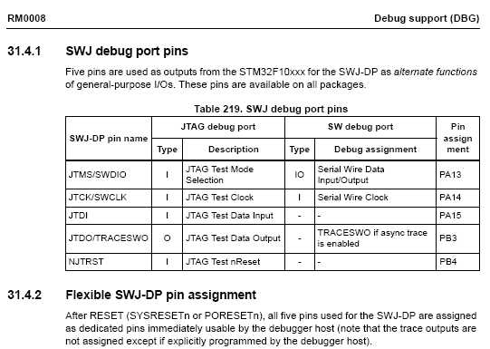
- stm32_dbg_port_pins.jpg (32.62 KiB) Viewed 400 times
[stevestrong – Sat Jan 12, 2019 2:21 pm] –
PB3, PB4:
stm32_dbg_port_pins.jpgCalling the above function makes PB3/PB4 available as GPIOs.
Regarding bin size, can you please post the (at least part of) build output to see which parameters are passed to the compiler?
USB_SERIAL is defined in boards.txt for upload with STLink, but it is not defined for serial upload.
So I assume that it is the USB serial code in my case which makes it bigger, but I would like to be sure.
So this is a silly beginner problem … ![]()
And now i must revise my opinion for STM32duino and go on with the real problem of this thread and find out howto code a complete byte access of the GPIO ports. ![]()
Here is the complete debug output from compilation:
/srv/bin/arduino-1.8.8/arduino-builder -dump-prefs -logger=machine -hardware /srv/bin/arduino-1.8.8/hardware -hardware /home/me/.arduino15/packages -tools /srv/bin/arduino-1.8.8/tools-builder -tools /srv/bin/arduino-1.8.8/hardware/tools/avr -tools /home/me/.arduino15/packages -built-in-libraries /srv/bin/arduino-1.8.8/libraries -libraries /win/AVR-GCC/Arduino/libraries -fqbn=stm32duino:STM32F1:genericSTM32F103C:device_variant=STM32F103C8,upload_method=serialMethod,cpu_speed=speed_72mhz,opt=osstd -ide-version=10808 -build-path /tmp/arduino_build_597151 -warnings=none -build-cache /tmp/arduino_cache_704300 -prefs=build.warn_data_percentage=75 -prefs=runtime.tools.stm32tools.path=/home/me/.arduino15/packages/stm32duino/tools/stm32tools/2018.12.3 -prefs=runtime.tools.stm32tools-2018.12.3.path=/home/me/.arduino15/packages/stm32duino/tools/stm32tools/2018.12.3 -prefs=runtime.tools.arm-none-eabi-gcc.path=/home/me/.arduino15/packages/arduino/tools/arm-none-eabi-gcc/4.8.3-2014q1 -prefs=runtime.tools.arm-none-eabi-gcc-4.8.3-2014q1.path=/home/me/.arduino15/packages/arduino/tools/arm-none-eabi-gcc/4.8.3-2014q1 -verbose /win/AVR-GCC/Arduino/LCD-Test/LCD-Test.ino

/srv/bin/arduino-1.8.8/arduino-builder -compile -logger=machine -hardware /srv/bin/arduino-1.8.8/hardware -hardware /home/me/.arduino15/packages -tools /srv/bin/arduino-1.8.8/tools-builder -tools /srv/bin/arduino-1.8.8/hardware/tools/avr -tools /home/me/.arduino15/packages -built-in-libraries /srv/bin/arduino-1.8.8/libraries -libraries /win/AVR-GCC/Arduino/libraries -fqbn=stm32duino:STM32F1:genericSTM32F103C:device_variant=STM32F103C8,upload_method=serialMethod,cpu_speed=speed_72mhz,opt=osstd -ide-version=10808 -build-path /tmp/arduino_build_597151 -warnings=none -build-cache /tmp/arduino_cache_704300 -prefs=build.warn_data_percentage=75 -prefs=runtime.tools.stm32tools.path=/home/me/.arduino15/packages/stm32duino/tools/stm32tools/2018.12.3 -prefs=runtime.tools.stm32tools-2018.12.3.path=/home/me/.arduino15/packages/stm32duino/tools/stm32tools/2018.12.3 -prefs=runtime.tools.arm-none-eabi-gcc.path=/home/me/.arduino15/packages/arduino/tools/arm-none-eabi-gcc/4.8.3-2014q1 -prefs=runtime.tools.arm-none-eabi-gcc-4.8.3-2014q1.path=/home/me/.arduino15/packages/arduino/tools/arm-none-eabi-gcc/4.8.3-2014q1 -verbose /win/AVR-GCC/Arduino/LCD-Test/LCD-Test.ino

Using board 'genericSTM32F103C' from platform in folder: /home/me/.arduino15/packages/stm32duino/hardware/STM32F1/2018.12.3

Using core 'maple' from platform in folder: /home/me/.arduino15/packages/stm32duino/hardware/STM32F1/2018.12.3

Detecting libraries used...

/home/me/.arduino15/packages/arduino/tools/arm-none-eabi-gcc/4.8.3-2014q1/bin/arm-none-eabi-g++ -c -g -Os -w -DDEBUG_LEVEL=DEBUG_NONE -std=gnu++11 -ffunction-sections -fdata-sections -nostdlib --param max-inline-insns-single=500 -fno-rtti -fno-exceptions -DBOARD_generic_stm32f103c -DVECT_TAB_ADDR=0x8000000 -DERROR_LED_PORT=GPIOC -DERROR_LED_PIN=13 -w -x c++ -E -CC -mcpu=cortex-m3 -DF_CPU=72000000L -DARDUINO=10808 -DARDUINO_GENERIC_STM32F103C -DARDUINO_ARCH_STM32F1 -DCONFIG_MAPLE_MINI_NO_DISABLE_DEBUG -DMCU_STM32F103C8 -mthumb -march=armv7-m -D__STM32F1__ -DARDUINO_ARCH_STM32 -DMCU_STM32F103C8 -mthumb -march=armv7-m -D__STM32F1__ -DARDUINO_ARCH_STM32 -I/home/me/.arduino15/packages/stm32duino/hardware/STM32F1/2018.12.3/system/libmaple -I/home/me/.arduino15/packages/stm32duino/hardware/STM32F1/2018.12.3/system/libmaple/include -I/home/me/.arduino15/packages/stm32duino/hardware/STM32F1/2018.12.3/system/libmaple/stm32f1/include -I/home/me/.arduino15/packages/stm32duino/hardware/STM32F1/2018.12.3/system/libmaple/usb/stm32f1 -I/home/me/.arduino15/packages/stm32duino/hardware/STM32F1/2018.12.3/system/libmaple/usb/usb_lib -I/home/me/.arduino15/packages/stm32duino/hardware/STM32F1/2018.12.3/cores/maple -I/home/me/.arduino15/packages/stm32duino/hardware/STM32F1/2018.12.3/variants/generic_stm32f103c /tmp/arduino_build_597151/sketch/LCD-Test.ino.cpp -o /dev/null

/home/me/.arduino15/packages/arduino/tools/arm-none-eabi-gcc/4.8.3-2014q1/bin/arm-none-eabi-g++ -c -g -Os -w -DDEBUG_LEVEL=DEBUG_NONE -std=gnu++11 -ffunction-sections -fdata-sections -nostdlib --param max-inline-insns-single=500 -fno-rtti -fno-exceptions -DBOARD_generic_stm32f103c -DVECT_TAB_ADDR=0x8000000 -DERROR_LED_PORT=GPIOC -DERROR_LED_PIN=13 -w -x c++ -E -CC -mcpu=cortex-m3 -DF_CPU=72000000L -DARDUINO=10808 -DARDUINO_GENERIC_STM32F103C -DARDUINO_ARCH_STM32F1 -DCONFIG_MAPLE_MINI_NO_DISABLE_DEBUG -DMCU_STM32F103C8 -mthumb -march=armv7-m -D__STM32F1__ -DARDUINO_ARCH_STM32 -DMCU_STM32F103C8 -mthumb -march=armv7-m -D__STM32F1__ -DARDUINO_ARCH_STM32 -I/home/me/.arduino15/packages/stm32duino/hardware/STM32F1/2018.12.3/system/libmaple -I/home/me/.arduino15/packages/stm32duino/hardware/STM32F1/2018.12.3/system/libmaple/include -I/home/me/.arduino15/packages/stm32duino/hardware/STM32F1/2018.12.3/system/libmaple/stm32f1/include -I/home/me/.arduino15/packages/stm32duino/hardware/STM32F1/2018.12.3/system/libmaple/usb/stm32f1 -I/home/me/.arduino15/packages/stm32duino/hardware/STM32F1/2018.12.3/system/libmaple/usb/usb_lib -I/home/me/.arduino15/packages/stm32duino/hardware/STM32F1/2018.12.3/cores/maple -I/home/me/.arduino15/packages/stm32duino/hardware/STM32F1/2018.12.3/variants/generic_stm32f103c -I/home/me/.arduino15/packages/stm32duino/hardware/STM32F1/2018.12.3/libraries/LiquidCrystal /tmp/arduino_build_597151/sketch/LCD-Test.ino.cpp -o /dev/null

/home/me/.arduino15/packages/arduino/tools/arm-none-eabi-gcc/4.8.3-2014q1/bin/arm-none-eabi-g++ -c -g -Os -w -DDEBUG_LEVEL=DEBUG_NONE -std=gnu++11 -ffunction-sections -fdata-sections -nostdlib --param max-inline-insns-single=500 -fno-rtti -fno-exceptions -DBOARD_generic_stm32f103c -DVECT_TAB_ADDR=0x8000000 -DERROR_LED_PORT=GPIOC -DERROR_LED_PIN=13 -w -x c++ -E -CC -mcpu=cortex-m3 -DF_CPU=72000000L -DARDUINO=10808 -DARDUINO_GENERIC_STM32F103C -DARDUINO_ARCH_STM32F1 -DCONFIG_MAPLE_MINI_NO_DISABLE_DEBUG -DMCU_STM32F103C8 -mthumb -march=armv7-m -D__STM32F1__ -DARDUINO_ARCH_STM32 -DMCU_STM32F103C8 -mthumb -march=armv7-m -D__STM32F1__ -DARDUINO_ARCH_STM32 -I/home/me/.arduino15/packages/stm32duino/hardware/STM32F1/2018.12.3/system/libmaple -I/home/me/.arduino15/packages/stm32duino/hardware/STM32F1/2018.12.3/system/libmaple/include -I/home/me/.arduino15/packages/stm32duino/hardware/STM32F1/2018.12.3/system/libmaple/stm32f1/include -I/home/me/.arduino15/packages/stm32duino/hardware/STM32F1/2018.12.3/system/libmaple/usb/stm32f1 -I/home/me/.arduino15/packages/stm32duino/hardware/STM32F1/2018.12.3/system/libmaple/usb/usb_lib -I/home/me/.arduino15/packages/stm32duino/hardware/STM32F1/2018.12.3/cores/maple -I/home/me/.arduino15/packages/stm32duino/hardware/STM32F1/2018.12.3/variants/generic_stm32f103c -I/home/me/.arduino15/packages/stm32duino/hardware/STM32F1/2018.12.3/libraries/LiquidCrystal /home/me/.arduino15/packages/stm32duino/hardware/STM32F1/2018.12.3/libraries/LiquidCrystal/LiquidCrystal.cpp -o /dev/null

Generating function prototypes...

/home/me/.arduino15/packages/arduino/tools/arm-none-eabi-gcc/4.8.3-2014q1/bin/arm-none-eabi-g++ -c -g -Os -w -DDEBUG_LEVEL=DEBUG_NONE -std=gnu++11 -ffunction-sections -fdata-sections -nostdlib --param max-inline-insns-single=500 -fno-rtti -fno-exceptions -DBOARD_generic_stm32f103c -DVECT_TAB_ADDR=0x8000000 -DERROR_LED_PORT=GPIOC -DERROR_LED_PIN=13 -w -x c++ -E -CC -mcpu=cortex-m3 -DF_CPU=72000000L -DARDUINO=10808 -DARDUINO_GENERIC_STM32F103C -DARDUINO_ARCH_STM32F1 -DCONFIG_MAPLE_MINI_NO_DISABLE_DEBUG -DMCU_STM32F103C8 -mthumb -march=armv7-m -D__STM32F1__ -DARDUINO_ARCH_STM32 -DMCU_STM32F103C8 -mthumb -march=armv7-m -D__STM32F1__ -DARDUINO_ARCH_STM32 -I/home/me/.arduino15/packages/stm32duino/hardware/STM32F1/2018.12.3/system/libmaple -I/home/me/.arduino15/packages/stm32duino/hardware/STM32F1/2018.12.3/system/libmaple/include -I/home/me/.arduino15/packages/stm32duino/hardware/STM32F1/2018.12.3/system/libmaple/stm32f1/include -I/home/me/.arduino15/packages/stm32duino/hardware/STM32F1/2018.12.3/system/libmaple/usb/stm32f1 -I/home/me/.arduino15/packages/stm32duino/hardware/STM32F1/2018.12.3/system/libmaple/usb/usb_lib -I/home/me/.arduino15/packages/stm32duino/hardware/STM32F1/2018.12.3/cores/maple -I/home/me/.arduino15/packages/stm32duino/hardware/STM32F1/2018.12.3/variants/generic_stm32f103c -I/home/me/.arduino15/packages/stm32duino/hardware/STM32F1/2018.12.3/libraries/LiquidCrystal /tmp/arduino_build_597151/sketch/LCD-Test.ino.cpp -o /tmp/arduino_build_597151/preproc/ctags_target_for_gcc_minus_e.cpp

/srv/bin/arduino-1.8.8/tools-builder/ctags/5.8-arduino11/ctags -u --language-force=c++ -f - --c++-kinds=svpf --fields=KSTtzns --line-directives /tmp/arduino_build_597151/preproc/ctags_target_for_gcc_minus_e.cpp

Sketch wird kompiliert...

/home/me/.arduino15/packages/arduino/tools/arm-none-eabi-gcc/4.8.3-2014q1/bin/arm-none-eabi-g++ -c -g -Os -w -DDEBUG_LEVEL=DEBUG_NONE -std=gnu++11 -MMD -ffunction-sections -fdata-sections -nostdlib --param max-inline-insns-single=500 -fno-rtti -fno-exceptions -DBOARD_generic_stm32f103c -DVECT_TAB_ADDR=0x8000000 -DERROR_LED_PORT=GPIOC -DERROR_LED_PIN=13 -mcpu=cortex-m3 -DF_CPU=72000000L -DARDUINO=10808 -DARDUINO_GENERIC_STM32F103C -DARDUINO_ARCH_STM32F1 -DCONFIG_MAPLE_MINI_NO_DISABLE_DEBUG -DMCU_STM32F103C8 -mthumb -march=armv7-m -D__STM32F1__ -DARDUINO_ARCH_STM32 -DMCU_STM32F103C8 -mthumb -march=armv7-m -D__STM32F1__ -DARDUINO_ARCH_STM32 -I/home/me/.arduino15/packages/stm32duino/hardware/STM32F1/2018.12.3/system/libmaple -I/home/me/.arduino15/packages/stm32duino/hardware/STM32F1/2018.12.3/system/libmaple/include -I/home/me/.arduino15/packages/stm32duino/hardware/STM32F1/2018.12.3/system/libmaple/stm32f1/include -I/home/me/.arduino15/packages/stm32duino/hardware/STM32F1/2018.12.3/system/libmaple/usb/stm32f1 -I/home/me/.arduino15/packages/stm32duino/hardware/STM32F1/2018.12.3/system/libmaple/usb/usb_lib -I/home/me/.arduino15/packages/stm32duino/hardware/STM32F1/2018.12.3/cores/maple -I/home/me/.arduino15/packages/stm32duino/hardware/STM32F1/2018.12.3/variants/generic_stm32f103c -I/home/me/.arduino15/packages/stm32duino/hardware/STM32F1/2018.12.3/libraries/LiquidCrystal /tmp/arduino_build_597151/sketch/LCD-Test.ino.cpp -o /tmp/arduino_build_597151/sketch/LCD-Test.ino.cpp.o

Compiling libraries...

Compiling library "LiquidCrystal"

/home/me/.arduino15/packages/arduino/tools/arm-none-eabi-gcc/4.8.3-2014q1/bin/arm-none-eabi-g++ -c -g -Os -w -DDEBUG_LEVEL=DEBUG_NONE -std=gnu++11 -MMD -ffunction-sections -fdata-sections -nostdlib --param max-inline-insns-single=500 -fno-rtti -fno-exceptions -DBOARD_generic_stm32f103c -DVECT_TAB_ADDR=0x8000000 -DERROR_LED_PORT=GPIOC -DERROR_LED_PIN=13 -mcpu=cortex-m3 -DF_CPU=72000000L -DARDUINO=10808 -DARDUINO_GENERIC_STM32F103C -DARDUINO_ARCH_STM32F1 -DCONFIG_MAPLE_MINI_NO_DISABLE_DEBUG -DMCU_STM32F103C8 -mthumb -march=armv7-m -D__STM32F1__ -DARDUINO_ARCH_STM32 -DMCU_STM32F103C8 -mthumb -march=armv7-m -D__STM32F1__ -DARDUINO_ARCH_STM32 -I/home/me/.arduino15/packages/stm32duino/hardware/STM32F1/2018.12.3/system/libmaple -I/home/me/.arduino15/packages/stm32duino/hardware/STM32F1/2018.12.3/system/libmaple/include -I/home/me/.arduino15/packages/stm32duino/hardware/STM32F1/2018.12.3/system/libmaple/stm32f1/include -I/home/me/.arduino15/packages/stm32duino/hardware/STM32F1/2018.12.3/system/libmaple/usb/stm32f1 -I/home/me/.arduino15/packages/stm32duino/hardware/STM32F1/2018.12.3/system/libmaple/usb/usb_lib -I/home/me/.arduino15/packages/stm32duino/hardware/STM32F1/2018.12.3/cores/maple -I/home/me/.arduino15/packages/stm32duino/hardware/STM32F1/2018.12.3/variants/generic_stm32f103c -I/home/me/.arduino15/packages/stm32duino/hardware/STM32F1/2018.12.3/libraries/LiquidCrystal /home/me/.arduino15/packages/stm32duino/hardware/STM32F1/2018.12.3/libraries/LiquidCrystal/LiquidCrystal.cpp -o /tmp/arduino_build_597151/libraries/LiquidCrystal/LiquidCrystal.cpp.o

Compiling core...

/home/me/.arduino15/packages/arduino/tools/arm-none-eabi-gcc/4.8.3-2014q1/bin/arm-none-eabi-gcc -c -g -x assembler-with-cpp -MMD -mcpu=cortex-m3 -DF_CPU=72000000L -DARDUINO=10808 -DARDUINO_GENERIC_STM32F103C -DARDUINO_ARCH_STM32F1 -DCONFIG_MAPLE_MINI_NO_DISABLE_DEBUG -DMCU_STM32F103C8 -mthumb -march=armv7-m -D__STM32F1__ -DARDUINO_ARCH_STM32 -DMCU_STM32F103C8 -mthumb -march=armv7-m -D__STM32F1__ -DARDUINO_ARCH_STM32 -I/home/me/.arduino15/packages/stm32duino/hardware/STM32F1/2018.12.3/system/libmaple -I/home/me/.arduino15/packages/stm32duino/hardware/STM32F1/2018.12.3/system/libmaple/include -I/home/me/.arduino15/packages/stm32duino/hardware/STM32F1/2018.12.3/system/libmaple/stm32f1/include -I/home/me/.arduino15/packages/stm32duino/hardware/STM32F1/2018.12.3/system/libmaple/usb/stm32f1 -I/home/me/.arduino15/packages/stm32duino/hardware/STM32F1/2018.12.3/system/libmaple/usb/usb_lib -I/home/me/.arduino15/packages/stm32duino/hardware/STM32F1/2018.12.3/cores/maple -I/home/me/.arduino15/packages/stm32duino/hardware/STM32F1/2018.12.3/variants/generic_stm32f103c /home/me/.arduino15/packages/stm32duino/hardware/STM32F1/2018.12.3/variants/generic_stm32f103c/wirish/start.S -o /tmp/arduino_build_597151/core/wirish/start.S.o

/home/me/.arduino15/packages/arduino/tools/arm-none-eabi-gcc/4.8.3-2014q1/bin/arm-none-eabi-gcc -c -g -Os -w -DDEBUG_LEVEL=DEBUG_NONE -std=gnu11 -MMD -ffunction-sections -fdata-sections -nostdlib --param max-inline-insns-single=500 -DBOARD_generic_stm32f103c -DVECT_TAB_ADDR=0x8000000 -DERROR_LED_PORT=GPIOC -DERROR_LED_PIN=13 -mcpu=cortex-m3 -DF_CPU=72000000L -DARDUINO=10808 -DARDUINO_GENERIC_STM32F103C -DARDUINO_ARCH_STM32F1 -DCONFIG_MAPLE_MINI_NO_DISABLE_DEBUG -DMCU_STM32F103C8 -mthumb -march=armv7-m -D__STM32F1__ -DARDUINO_ARCH_STM32 -I/home/me/.arduino15/packages/stm32duino/hardware/STM32F1/2018.12.3/system/libmaple -I/home/me/.arduino15/packages/stm32duino/hardware/STM32F1/2018.12.3/system/libmaple/include -I/home/me/.arduino15/packages/stm32duino/hardware/STM32F1/2018.12.3/system/libmaple/stm32f1/include -I/home/me/.arduino15/packages/stm32duino/hardware/STM32F1/2018.12.3/system/libmaple/usb/stm32f1 -I/home/me/.arduino15/packages/stm32duino/hardware/STM32F1/2018.12.3/system/libmaple/usb/usb_lib -I/home/me/.arduino15/packages/stm32duino/hardware/STM32F1/2018.12.3/cores/maple -I/home/me/.arduino15/packages/stm32duino/hardware/STM32F1/2018.12.3/variants/generic_stm32f103c /home/me/.arduino15/packages/stm32duino/hardware/STM32F1/2018.12.3/variants/generic_stm32f103c/wirish/start_c.c -o /tmp/arduino_build_597151/core/wirish/start_c.c.o

/home/me/.arduino15/packages/arduino/tools/arm-none-eabi-gcc/4.8.3-2014q1/bin/arm-none-eabi-gcc -c -g -Os -w -DDEBUG_LEVEL=DEBUG_NONE -std=gnu11 -MMD -ffunction-sections -fdata-sections -nostdlib --param max-inline-insns-single=500 -DBOARD_generic_stm32f103c -DVECT_TAB_ADDR=0x8000000 -DERROR_LED_PORT=GPIOC -DERROR_LED_PIN=13 -mcpu=cortex-m3 -DF_CPU=72000000L -DARDUINO=10808 -DARDUINO_GENERIC_STM32F103C -DARDUINO_ARCH_STM32F1 -DCONFIG_MAPLE_MINI_NO_DISABLE_DEBUG -DMCU_STM32F103C8 -mthumb -march=armv7-m -D__STM32F1__ -DARDUINO_ARCH_STM32 -I/home/me/.arduino15/packages/stm32duino/hardware/STM32F1/2018.12.3/system/libmaple -I/home/me/.arduino15/packages/stm32duino/hardware/STM32F1/2018.12.3/system/libmaple/include -I/home/me/.arduino15/packages/stm32duino/hardware/STM32F1/2018.12.3/system/libmaple/stm32f1/include -I/home/me/.arduino15/packages/stm32duino/hardware/STM32F1/2018.12.3/system/libmaple/usb/stm32f1 -I/home/me/.arduino15/packages/stm32duino/hardware/STM32F1/2018.12.3/system/libmaple/usb/usb_lib -I/home/me/.arduino15/packages/stm32duino/hardware/STM32F1/2018.12.3/cores/maple -I/home/me/.arduino15/packages/stm32duino/hardware/STM32F1/2018.12.3/variants/generic_stm32f103c /home/me/.arduino15/packages/stm32duino/hardware/STM32F1/2018.12.3/variants/generic_stm32f103c/wirish/syscalls.c -o /tmp/arduino_build_597151/core/wirish/syscalls.c.o

/home/me/.arduino15/packages/arduino/tools/arm-none-eabi-gcc/4.8.3-2014q1/bin/arm-none-eabi-g++ -c -g -Os -w -DDEBUG_LEVEL=DEBUG_NONE -std=gnu++11 -MMD -ffunction-sections -fdata-sections -nostdlib --param max-inline-insns-single=500 -fno-rtti -fno-exceptions -DBOARD_generic_stm32f103c -DVECT_TAB_ADDR=0x8000000 -DERROR_LED_PORT=GPIOC -DERROR_LED_PIN=13 -mcpu=cortex-m3 -DF_CPU=72000000L -DARDUINO=10808 -DARDUINO_GENERIC_STM32F103C -DARDUINO_ARCH_STM32F1 -DCONFIG_MAPLE_MINI_NO_DISABLE_DEBUG -DMCU_STM32F103C8 -mthumb -march=armv7-m -D__STM32F1__ -DARDUINO_ARCH_STM32 -DMCU_STM32F103C8 -mthumb -march=armv7-m -D__STM32F1__ -DARDUINO_ARCH_STM32 -I/home/me/.arduino15/packages/stm32duino/hardware/STM32F1/2018.12.3/system/libmaple -I/home/me/.arduino15/packages/stm32duino/hardware/STM32F1/2018.12.3/system/libmaple/include -I/home/me/.arduino15/packages/stm32duino/hardware/STM32F1/2018.12.3/system/libmaple/stm32f1/include -I/home/me/.arduino15/packages/stm32duino/hardware/STM32F1/2018.12.3/system/libmaple/usb/stm32f1 -I/home/me/.arduino15/packages/stm32duino/hardware/STM32F1/2018.12.3/system/libmaple/usb/usb_lib -I/home/me/.arduino15/packages/stm32duino/hardware/STM32F1/2018.12.3/cores/maple -I/home/me/.arduino15/packages/stm32duino/hardware/STM32F1/2018.12.3/variants/generic_stm32f103c /home/me/.arduino15/packages/stm32duino/hardware/STM32F1/2018.12.3/variants/generic_stm32f103c/board.cpp -o /tmp/arduino_build_597151/core/board.cpp.o

/home/me/.arduino15/packages/arduino/tools/arm-none-eabi-gcc/4.8.3-2014q1/bin/arm-none-eabi-g++ -c -g -Os -w -DDEBUG_LEVEL=DEBUG_NONE -std=gnu++11 -MMD -ffunction-sections -fdata-sections -nostdlib --param max-inline-insns-single=500 -fno-rtti -fno-exceptions -DBOARD_generic_stm32f103c -DVECT_TAB_ADDR=0x8000000 -DERROR_LED_PORT=GPIOC -DERROR_LED_PIN=13 -mcpu=cortex-m3 -DF_CPU=72000000L -DARDUINO=10808 -DARDUINO_GENERIC_STM32F103C -DARDUINO_ARCH_STM32F1 -DCONFIG_MAPLE_MINI_NO_DISABLE_DEBUG -DMCU_STM32F103C8 -mthumb -march=armv7-m -D__STM32F1__ -DARDUINO_ARCH_STM32 -DMCU_STM32F103C8 -mthumb -march=armv7-m -D__STM32F1__ -DARDUINO_ARCH_STM32 -I/home/me/.arduino15/packages/stm32duino/hardware/STM32F1/2018.12.3/system/libmaple -I/home/me/.arduino15/packages/stm32duino/hardware/STM32F1/2018.12.3/system/libmaple/include -I/home/me/.arduino15/packages/stm32duino/hardware/STM32F1/2018.12.3/system/libmaple/stm32f1/include -I/home/me/.arduino15/packages/stm32duino/hardware/STM32F1/2018.12.3/system/libmaple/usb/stm32f1 -I/home/me/.arduino15/packages/stm32duino/hardware/STM32F1/2018.12.3/system/libmaple/usb/usb_lib -I/home/me/.arduino15/packages/stm32duino/hardware/STM32F1/2018.12.3/cores/maple -I/home/me/.arduino15/packages/stm32duino/hardware/STM32F1/2018.12.3/variants/generic_stm32f103c /home/me/.arduino15/packages/stm32duino/hardware/STM32F1/2018.12.3/variants/generic_stm32f103c/wirish/boards.cpp -o /tmp/arduino_build_597151/core/wirish/boards.cpp.o

/home/me/.arduino15/packages/arduino/tools/arm-none-eabi-gcc/4.8.3-2014q1/bin/arm-none-eabi-g++ -c -g -Os -w -DDEBUG_LEVEL=DEBUG_NONE -std=gnu++11 -MMD -ffunction-sections -fdata-sections -nostdlib --param max-inline-insns-single=500 -fno-rtti -fno-exceptions -DBOARD_generic_stm32f103c -DVECT_TAB_ADDR=0x8000000 -DERROR_LED_PORT=GPIOC -DERROR_LED_PIN=13 -mcpu=cortex-m3 -DF_CPU=72000000L -DARDUINO=10808 -DARDUINO_GENERIC_STM32F103C -DARDUINO_ARCH_STM32F1 -DCONFIG_MAPLE_MINI_NO_DISABLE_DEBUG -DMCU_STM32F103C8 -mthumb -march=armv7-m -D__STM32F1__ -DARDUINO_ARCH_STM32 -DMCU_STM32F103C8 -mthumb -march=armv7-m -D__STM32F1__ -DARDUINO_ARCH_STM32 -I/home/me/.arduino15/packages/stm32duino/hardware/STM32F1/2018.12.3/system/libmaple -I/home/me/.arduino15/packages/stm32duino/hardware/STM32F1/2018.12.3/system/libmaple/include -I/home/me/.arduino15/packages/stm32duino/hardware/STM32F1/2018.12.3/system/libmaple/stm32f1/include -I/home/me/.arduino15/packages/stm32duino/hardware/STM32F1/2018.12.3/system/libmaple/usb/stm32f1 -I/home/me/.arduino15/packages/stm32duino/hardware/STM32F1/2018.12.3/system/libmaple/usb/usb_lib -I/home/me/.arduino15/packages/stm32duino/hardware/STM32F1/2018.12.3/cores/maple -I/home/me/.arduino15/packages/stm32duino/hardware/STM32F1/2018.12.3/variants/generic_stm32f103c /home/me/.arduino15/packages/stm32duino/hardware/STM32F1/2018.12.3/variants/generic_stm32f103c/wirish/boards_setup.cpp -o /tmp/arduino_build_597151/core/wirish/boards_setup.cpp.o

Using precompiled core: /tmp/arduino_cache_704300/core/core_11dd8c8e52a7a191bcf2e2785ef7f974.a

Linking everything together...

/home/me/.arduino15/packages/arduino/tools/arm-none-eabi-gcc/4.8.3-2014q1/bin/arm-none-eabi-g++ -Os -Wl,--gc-sections -mcpu=cortex-m3 -T/home/me/.arduino15/packages/stm32duino/hardware/STM32F1/2018.12.3/variants/generic_stm32f103c/ld/jtag_c8.ld -Wl,-Map,/tmp/arduino_build_597151/LCD-Test.ino.map -L/home/me/.arduino15/packages/stm32duino/hardware/STM32F1/2018.12.3/variants/generic_stm32f103c/ld -o /tmp/arduino_build_597151/LCD-Test.ino.elf -L/tmp/arduino_build_597151 -lm -lgcc -mthumb -Wl,--cref -Wl,--check-sections -Wl,--gc-sections -Wl,--unresolved-symbols=report-all -Wl,--warn-common -Wl,--warn-section-align -Wl,--warn-unresolved-symbols -Wl,--start-group /tmp/arduino_build_597151/sketch/LCD-Test.ino.cpp.o /tmp/arduino_build_597151/libraries/LiquidCrystal/LiquidCrystal.cpp.o /tmp/arduino_build_597151/core/board.cpp.o /tmp/arduino_build_597151/core/wirish/boards.cpp.o /tmp/arduino_build_597151/core/wirish/boards_setup.cpp.o /tmp/arduino_build_597151/core/wirish/start.S.o /tmp/arduino_build_597151/core/wirish/start_c.c.o /tmp/arduino_build_597151/core/wirish/syscalls.c.o /tmp/arduino_cache_704300/core/core_11dd8c8e52a7a191bcf2e2785ef7f974.a -Wl,--end-group

/home/me/.arduino15/packages/arduino/tools/arm-none-eabi-gcc/4.8.3-2014q1/bin/arm-none-eabi-objcopy -O binary /tmp/arduino_build_597151/LCD-Test.ino.elf /tmp/arduino_build_597151/LCD-Test.ino.bin

Mehrere Bibliotheken wurden für "LiquidCrystal.h" gefunden

Benutzt: /home/me/.arduino15/packages/stm32duino/hardware/STM32F1/2018.12.3/libraries/LiquidCrystal

Nicht benutzt: /srv/bin/arduino-1.8.8/libraries/Newliquidcrystal

Nicht benutzt: /srv/bin/arduino-1.8.8/libraries/LiquidCrystal

Bibliothek LiquidCrystal im Ordner: /home/me/.arduino15/packages/stm32duino/hardware/STM32F1/2018.12.3/libraries/LiquidCrystal (legacy) wird verwendet

/home/me/.arduino15/packages/arduino/tools/arm-none-eabi-gcc/4.8.3-2014q1/bin/arm-none-eabi-size -A /tmp/arduino_build_597151/LCD-Test.ino.elf

Der Sketch verwendet 13720 Bytes (20%) des Programmspeicherplatzes. Das Maximum sind 65536 Bytes.

Globale Variablen verwenden 2488 Bytes (12%) des dynamischen Speichers, 17992 Bytes für lokale Variablen verbleiben. Das Maximum sind 20480 Bytes.
You will need it to understand the GIPO accesses as well.
viewtopic.php?f=3&t=3763&p=46320
Set/reset only some of the bits: look for BSRR.
For accessing the GPIO i see more problems in the initialization.
Is it only the mode of the Pins (input, output) and the signal that must be set?
What’s about the GPIO clock – is it set with the standard initialization for all ports?
Here some additional pointers how to set pin mode: https://github.com/stevstrong/Adafruit_ … h#L98-L103
and how to write a value: https://github.com/stevstrong/Adafruit_ … M32.h#L118
[lsmod – Sat Jan 12, 2019 3:51 pm] –
Reading the whole bible is one problem – recognizing it another.
For accessing the GPIO i see more problems in the initialization.
Is it only the mode of the Pins (input, output) and the signal that must be set?
What’s about the GPIO clock – is it set with the standard initialization for all ports?
There are lots of material, some free, on the STM32 architecture: https://www.st.com/content/st_com/en/su … books.html
Actually, I would prefer that you just forget about the “clone” cores and use the STM32 Official Core which does things the way the chip designers intend. There will always be issues around the old LeafLab’s core … issues which can only be summarized as, “It is just because that is how they did things…”
As for the bootloader and initialization routine, I know Roger made some major enhancements, but I cannot remember (I need to study the change logs) any changes to the Leaflabs bootloader as far as initialization. But, I recommend not using a bootloader, ST-Link or serial TTL is a superior upload methodology, IMO. http://wiki.stm32duino.com/index.php?ti … g_a_sketch
Ray
[stevestrong – Sat Jan 12, 2019 4:20 pm] –
Here some additional pointers how to set pin mode: https://github.com/stevstrong/Adafruit_ … h#L98-L103
and how to write a value: https://github.com/stevstrong/Adafruit_ … M32.h#L118
Thanks – that’s what i searched for.
I will try this out and make a short demo code.
When it is working i will post it here.
[mrburnette – Sat Jan 12, 2019 9:26 pm] –
Actually, I would prefer that you just forget about the “clone” cores and use the STM32 Official Core which does things the way the chip designers intend. There will always be issues around the old LeafLab’s core … issues which can only be summarized as, “It is just because that is how they did things…”
The difference between the cores is still not clear for me.
I already asked this here viewtopic.php?f=28&t=4474&start=10#p51947
You have written a nice overview viewtopic.php?f=2&t=3111, but there is no description what the difference is between this cores?
I only understand that there are complete different basic libraries like the “Maple core” here or “libopencm3”.
But when you start you have no idea what you need later on and where you get the better implementation for it.
So i am simply glad when i just know how to do what i want or if it is possible to do it.
Additional there are alternating confusing names like “Leaflabs-based core” and “Maple core”.
For libopencm3 there is an overview for the implemented functionality http://libopencm3.org/docs/latest/stm32 … dules.html
[lsmod – Sun Jan 13, 2019 9:34 am] –
…
The difference between the cores is still not clear for me.
I already asked this here viewtopic.php?f=28&t=4474&start=10#p51947
You have written a nice overview viewtopic.php?f=2&t=3111, but there is no description what the difference is between this cores?
…
For your purpose, the big differences are the software architecture and API:
Introduction
This repo adds the support of STM32 MCU in Arduino IDE.
This porting is based on:
STM32Cube MCU Packages including:
The HAL hardware abstraction layer, enabling portability between different STM32 devices via standardized API calls
The Low-Layer (LL) APIs, a light-weight, optimized, expert oriented set of APIs designed for both performance and runtime efficiency
CMSIS device defintion for STM32
CMSIS: Cortex Microcontroller Software Interface Standard (CMSIS) is a vendor-independent hardware abstraction layer for the Cortex®-M processor series and defines generic tool interfaces. It has been packaged as a module for Arduino IDE: https://github.com/stm32duino/ArduinoModule-CMSIS
GNU Arm Embedded Toolchain: Arm Embedded GCC compiler, libraries and other GNU tools necessary for bare-metal software development on devices based on the Arm Cortex-M. Packages are provided thanks: https://github.com/stm32duino/arm-none-eabi-gcc
The other difference to note is this forum is about to close and you are going to be left with Roger’s core with some patches applied and no where to complain ask questions; essentially in nowhere land. Fine for those of us self-sufficient but really not good for a user who is relying on others and a continuing dialog.
LeafLabs is an engineering company that designed the first STM32F103 Arduino’ish boards:
https://www.leaflabs.com/maple
They also wrote libmaple:
[INACTIVE] libmaple
libmaple is inactive and no longer accepting submissions.
libmaple is a library for programming ST’s STM32 line of Cortex M3
microcontrollers. It has a pure C layer, libmaple proper, which does
most of the work, and a C++ layer, Wirish, which provides high-level
convenience functions and a Wiring/Arduino-compatible interface.
libmaple is designed for portability, and currently runs on a variety
of STM32F1 performance and value line MCUs, with experimental support
for STM32F2 MCUs.
So, essentially you need to migrate to STM’s official core or learn to quickly become proficient with maintaining the version Roger hosts on github.
Ray
[stevestrong – Sat Jan 12, 2019 4:20 pm] –
Here some additional pointers how to set pin mode: https://github.com/stevstrong/Adafruit_ … h#L98-L103
and how to write a value: https://github.com/stevstrong/Adafruit_ … M32.h#L118
Sorry – this is not really clear to understand:
extern gpio_reg_map * dataRegs;

#define setWriteDir() ( dataRegs->CRL = 0x33333333 )	// set the lower 8 bits as output
//set up 8 bit parallel port to write mode.
setWriteDir();
[mrburnette – Sun Jan 13, 2019 1:13 pm] –
The other difference to note is this forum is about to close and you are going to be left with Roger’s core with some patches applied and no where to complain ask questions; essentially in nowhere land. Fine for those of us self-sufficient but really not good for a user who is relying on others and a continuing dialog.LeafLabs is an engineering company that designed the first STM32F103 Arduino’ish boards:
https://www.leaflabs.com/maple
They also wrote libmaple:
[INACTIVE] libmaple
libmaple is inactive and no longer accepting submissions.So, essentially you need to migrate to STM’s official core or learn to quickly become proficient with maintaining the version Roger hosts on github.
So STM32duino is riding a dead horse? ![]()
![]()
The main problem with a move to the STM core for the less resource imbued chips is how much HAL/LL etc hogs them. For that reason I doubt this core will really ‘die’ once the forum goes read only, no matter how much some would like.
It compiles, but it produces just interesting output on the lower 8 bits of GPIOA.
It’s the same using the macro functions or the direct access.
// set the pins to input mode

#define setReadDir(r) ( r->regs->CRL = 0x88888888 )	// set the lower 8 bits as input

// set the pins to output mode

#define setWriteDir(r) ( r->regs->CRL = 0x33333333 )	// set the lower 8 bits as output
// use fast bit toggling, very fast speed!
#define Write8(r, c) { r->regs->ODR = (uint32_t)(0x00FF0000 + ((c)&0xFF)); }
#define Toggle8(r, c) { r->regs->BSRR = (uint32_t)(0x00FF0000 + ((c)&0xFF)); }
static uint32_t PortA;
void blink() {
digitalWrite(LED_BUILTIN, !digitalRead(LED_BUILTIN));
}
void setup() {
enableDebugPorts(); // use all pins
pinMode(LED_BUILTIN, OUTPUT); // blue pill LED PC13
setWriteDir(GPIOA);
PortA = GPIOA->regs->ODR & 0xFFFFFF00;
}
void loop() {
uint8_t i;
uint8_t BOut;
BOut = 0x01;
for(i = 1; i <= 7; i++ ) {
GPIOA->regs->ODR = PortA | (uint32_t)BOut;
// Write8(GPIOA, BOut);
BOut = BOut << 1; // Shift Left
// delay(100); // wait 100 ms
}
blink();
BOut = 0x80;
for(i = 1; i <= 7; i++ ) {
GPIOA->regs->ODR = PortA | (uint32_t)BOut;
// Write8(GPIOA, BOut);
BOut = BOut >> 1; // Shift Right
// delay(100); // wait 100 ms
}
blink();
}
[BennehBoy – Sun Jan 13, 2019 2:54 pm] –
Not necessarily, but the key maintainer right now does not have the time to move it forwards, and many of the ‘old hands’ have moved on to other things, stmcube, ESP, etc so their interest has waned.The main problem with a move to the STM core for the less resource imbued chips is how much HAL/LL etc hogs them. For that reason I doubt this core will really ‘die’ once the forum goes read only, no matter how much some would like.
Then the libmaple core was the dead horse. ![]()
But when this forum is closed and no one maintains STM32duino it will die.
So it makes more sense to learn working with libopencm3 or something else. ![]()
[lsmod – Sun Jan 13, 2019 3:30 pm] –
…
Then the libmaple core was the dead horse.
But when this forum is closed and no one maintains STM32duino it will die.
So it makes more sense to learn working with libopencm3 or something else.

I suspect Roger’s core, bootloader, and libmaple to continue to be used to some degree as there are numerous variations of same on github already. But if one is trying to study & learn the inner workings of the STM32F1xx, then I recommend to work with the only core for Arduino that is fully supported; the STM32 Arduino Core.
This is a young core but actively supported and based on the mature STM HAL, essentially the Arduino version is wrappers around the commercial versions of the code. Learning to code to HAL protects your investment in learning and eases your migration from Arduino to professional IDE+tools.
Ray
Just for grins:
The tribal wisdom of the Dakota Indians, passed on from generation to generation, says that, “When you discover that you are riding a dead horse, the best strategy is to dismount.”
In contrast, here’s how many people respond when they find out their “horse” is dead:
Say things like, “This is the way we always have ridden the horse.”
Appoint a committee to study the horse.
Buy a stronger whip.
Change riders.
Arrange to visit other locations to see how they ride dead horses.
Raise the standards for riding dead horses.
Appoint a triage team to revive the dead horse.
Create a training session to increase our riding ability.
Compare the state of dead horses in today’s business environment.
Change your definitionsor rules by declaring, “This horse is not dead.”
Hire outside consultants to ride the dead horse.
Harness several dead horses together to increase speed and pulling power.
Declare that “No horse is too dead to beat.”
Provide additional incentive funding (more sticks – more carrots) to increase the horse’s performance.
Do a case-study to see if competitors can ride it cheaper.
Purchase a software package or institute a new program to make dead horses run faster.
Declare that the horse is “better, faster, and cheaper” dead.
Form a quality circle to find uses for dead horses.
Revisit the performance requirements for dead horses.
Downsize the dead horse.
Reassign fault to the dead horse’s last rider.
Promote the dead horse to a supervisory position.
Shorten the track.
Declare the dead horse was “one of the leading horses” in its day.
Establish benchmarks for industry dead horse leaders.
Gather other dead animals and announce a new diversity program.
Put together a spiffy PowerPoint presentation to get planners to double the dead horse R & D budget.
Get the dead horse a web site!
[mrburnette – Sun Jan 13, 2019 4:34 pm] –
But if one is trying to study & learn the inner workings of the STM32F1xx, then I recommend to work with the only core for Arduino that is fully supported; the STM32 Arduino Core.
This is a young core but actively supported and based on the mature STM HAL, essentially the Arduino version is wrappers around the commercial versions of the code. Learning to code to HAL protects your investment in learning and eases your migration from Arduino to professional IDE+tools.
HAL as a new odyssey 2019 instead of 2001 ? ![]()
O.K. This horse seems to want keep alive. ![]()
Can you please give some more hints for “Learning to code to HAL” ?
Or in other words – how to code reading or writing 8 pins at once with your core?

Should be Hello Ray
Start with the manufacturers PDF reference files: https://www.st.com/en/embedded-software … ubef1.html
and add to that any of the many (lab) textbooks, the one below is free:
Discovering the STM32 Microcontroller by Geoffrey Brown
If you do not have one, buy an ST-Link or plan to use the serial in silicon implementation … bye, bye bootloader.
Everything above is the traditional approach. If you want to try HAL under Arduino, then https://github.com/stm32duino/Arduino_Core_STM32
You will have access to all the low-level source.
https://github.com/stm32duino/Arduino_C … uino/stm32
As for reading-writing a port, one method is:
Have fun and good luck.
Ray
[mrburnette – Sun Jan 13, 2019 5:33 pm] –
Have fun and good luck.Ray
Thank you Ray.
This looks for much work and cannot be done quickly.
I will test it and will see the results.
But honestly i will have a closer look at libopencm3 too.
[lsmod – Tue Jan 15, 2019 9:44 am] –
…
But honestly i will have a closer look at libopencm3 too.
Bravo. One should always be open to a better approach.
I have not utilized libopencm3, but a quick search of Google shows much activity; for example.
In my mind, it all comes down to your ultimate desire, that is what is drawing one to the STM32FXXX uC? Most of the original members here were drawn by the reasonable cost plus the increase in clock-speed & SRAM plus the challenge of running the uC under ArduinoIDE. But, some others came here because they were taking a university course that used STM32 hardware. For many, it has become a real workhorse and is their go-to uC. For myself, I’m just passed through and moved on to other SoC devices.
Ray
![[SOLVED] Discovery STM32F100RB — Trouble with timers and library structure](https://sparklogic.ru/wp-content/uploads/2019/11/st-stm32vl-discovery-90x90.jpg)
