I just found two samples which use two SPI as input/ output to a SD card, I’m trying to modify the samples however I can’t make it work for what I need
https://github.com/stevstrong/Audio-sam … C_Host.ino
download/file.php?id=623
To be honest I’m not sure what I have to do to setup SPI in slave mode.
Currently I have the blue pill using almost the whole PORTA sending a memory buffer to a RGB display making the SPI(1) unusable, the CPU spends a good amount of time to send the buffer to the RGB display so I have a ESP8266 that does image processing to blend several images in one, once the blending is done it sends the frame to the STM32 for display.
I already have the code in the ESP8266 to blend the images and is sending the frame over SPI to the STM (looks good with a logical analyzer)
Now, I want to receive the frame (about 6KB) in the SPI port 2 on my STM32 to render on the RGB display.
Can you provide some hints or a simplified sample how do I setup my SPI port 2 to work on slave mode, and get a callback or any way to get the buffer once is transferred?
Thanks.
#include <SPI.h>

#include <libmaple/dma.h>

#include "libmaple/spi.h"

...

/*****************************************************************************/

SPIClass SPI_2(2);

/*****************************************************************************/

void SPI_setup(void)

{

// use SPI 2 for recording

SPI_2.beginTransactionSlave(SPISettings(18000000, MSBFIRST, SPI_MODE0, DATA_SIZE_8BIT));

spi_rx_dma_enable(SPI_2.dev()); // enable SPI Rx DMA

}

/*****************************************************************************/

#define RECORDS_PER_BUFFER (6*1024)

uint8_t data_buffer[RECORDS_PER_BUFFER];

/*****************************************************************************/

void DMA_Setup(void)

{

dma_init(DMA1);	// init DMA clock domain

// DMA setup transfer for SPI2 Rx

dma_channel dma_ch = DMA_CH4; // SPI2 Rx DMA channel is channel 4, see reference manual 13.3.7.

dma_disable(DMA1, dma_ch);	// Disable the DMA tube.

dma_setup_transfer(DMA1, dma_ch,

&((SPI_2.dev())->regs->DR), DMA_SIZE_8BITS,

data_buffer, DMA_SIZE_8BITS,

(DMA_MINC_MODE | DMA_CIRC_MODE | DMA_HALF_TRNS | DMA_TRNS_CMPLT)); // flags

dma_set_num_transfers(DMA1, dma_ch, RECORDS_PER_BUFFER);

dma_set_priority(DMA1, dma_ch, DMA_PRIORITY_VERY_HIGH);

dma_attach_interrupt(DMA1, dma_ch, DMA_Rx_irq);	// attach an interrupt handler.

dma_enable(DMA1, dma_ch);	// Enable the DMA tube. It will now begin serving requests.

}

/*****************************************************************************/

// variables

// set by HW when a complete DMA transfer was finished.

volatile uint8_t dma_irq_full_complete;

// set by HW when a DMA transfer is at its half.

volatile uint8_t dma_irq_half_complete;

/*****************************************************************************/

// This is our DMA interrupt handler.

/*****************************************************************************/

void DMA_Rx_irq(void)

{

uint32_t dma_isr = dma_get_isr_bits(DMA1, DMA_CH4);

if (dma_isr&DMA_ISR_HTIF1) {

dma_irq_half_complete = 1; // signal for the main level

}

if (dma_isr&DMA_ISR_TCIF1) {

dma_irq_full_complete = 1; // signal for the main level

}

dma_clear_isr_bits(DMA1, DMA_CH4);

}
Thanks!!!
SPI on the master talk to a SD card and also to the STM, so the SPI bus is busy talking different slaves, I want to make sure that the DMA channel on the STM32 will be collecting the frame from the bus only when the SS (NSS2/PB12) is low.
How the dma channel knows? I don’t see this in either of the setup methods.
In slave mode the SPI will only receive data is SS pin is activated by the master, it is the default way of working.
The DMA is only triggered when new data comes in to SPI, so this is also automated by the hardware.
Checked the SPI2
PB12 -> CS
PB13 -> CLK
PB14 -> MISO
PB15 -> MOSI
I have the oscilloscope and the analyzer in the bus and everything looks fine, I simplified the master code just to send in repetition 32 bytes with the “Hello There” content.
Even on the STM32 I copied the method void REGS_info(void) from the samples and dump the content every second and I get the same:
DMA1.ISR: 0
DMA1.CCR2: 0
DMA1.CNDTR2: 0
SPI2.CR1: 440
SPI2.CR2: 0
SPI2.SR: 43
The interruption is never triggered, what else can I check?
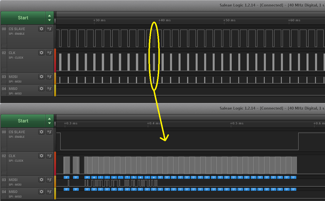
- SPIbus.png (101.75 KiB) Viewed 867 times
But anyway, I have found a very important step missing in the setup flow, it is the enabling the SPI Rx DMA.
This should be done by inserting an additional line to SPI setup:
#include "libmaple/spi.h"

...

void SPI_setup(void)

{

// use SPI 2 for recording

SPI_2.beginTransactionSlave(SPISettings(18000000, MSBFIRST, SPI_MODE0, DATA_SIZE_8BIT));

spi_rx_dma_enable(SPI_2.dev()); // enable SPI Rx DMA

}
Thanks a lot, now I’ll start to fix all mess in code changes I did in master and slave trying o figure out.
One more question, how transmission errors are handled?
For example I expect 6144 (6×1024) bytes, however if for some reason not all of the bytes are coming the buffer won’t be totally full and the main loop won’t detect the full buffer, the SS will go high and the IRQ won’t be triggered.
Now when the next frame comes, will the DMA channel start over from the beginning in the buffer or will continue where it left off.
If continue where it left in the previous frame then a single byte loss can trigger a massive mess chain reaction in the buffer.
How usually errors are dealt?
Basically I’m not concerned if I lose a frame, however I want to make sure for every SS low the DMA start to write from the beginning in the buffer.
Alternatively, you could signal the start of the frame with a nother pin to trIgger an interrpt wich resets the DMA before starting the frame, before NSS goes low.
On the master I could give several microseconds as a time buffer after SS go LOW and start to transmit the data, that time should be enough for the slave to get the SS IRQ and init the DMA buffer, that way I would not need an extra pin.
If not, then connect same wire to another pin, too.
I’m almost there, I fixed the code on Master and Slave and it works like a dream master sending the frames and slave consuming them in real time, however I can’ t get more than 35Mhz.
Right now is very unoptimized on the slave. It creates a buffer for the DMA then when is completed does a memcopy to the video buffer.
Currently I’m running the RGB with double buffer, so I don’t really need another buffer, I want the DMA channel to write on the RGB backbuffer, once the frame is received I just want to swap the back buffer for the front buffer on the display, so the operation is immediate and the “new” back buffer is ready to be filled by DMA.
I haven’t try yet, however on the IRQ function I need to do something like:
void DMA_Rx_irq(void)

{

uint32_t dma_isr = dma_get_isr_bits(DMA1, DMA_CH4);

if (dma_isr & DMA_ISR_TCIF1)

{

matrix.swapBuffer();

byte* backBuffer = matrix.backBuffer();

dma_setup_transfer(DMA1, dma_ch,

&((spi2.dev())->regs->DR), DMA_SIZE_8BITS,

backBuffer, DMA_SIZE_8BITS,

(DMA_MINC_MODE | DMA_CIRC_MODE | DMA_HALF_TRNS | DMA_TRNS_CMPLT)); // flags

}

dma_clear_isr_bits(DMA1, DMA_CH4);

}
If not, then you can use the same double buffer to receive the data directly into the RGB buffer.
Make the DMA buffer circular (which is actually the case in my example) and set it to the RGB buffer and forget about everything.
There is no need to re-init the DMA if nothing changes, it will continuously write the double buffers from the beginning when it finishes (that is why “circular”).
I think I got what you are saying.
New steps:
Allocate a single consecutive frame buffer * 2 to hold two frames 6144 * 2 (currently I have two distinct 6144 buffers)
On the matrix the buffers will be
byte videoBuffer[12288];
*frontBuffer = videoBuffer;
*backBuffer = videoBuffer + 6144
On DMA setup function I’ll have to provide the pointer to the videobuffer and I have to tell that I have 2 records of 6144 instead only 1.
then I call matrix.swapbuffer() when the IRQ triggers for both Half And Full, that way DMA will fill two frames before automatically resets since is circular.
I think will work great, I was thinking to DMA fill always the backbuffer that is not show on the screen and for every Full completed buffer call the swapbuffer() however that would require to move the ptr where the DMA needs to write after every frame, the solution that you propose sounds much simpler, only caveat is that I need to allocate the 2 video buffer as a single consecutive buffer, the STM32 has 20K and I need to take 12K so probably I’ll have to allocate this buffer as soon the code start to avoid hit memory fragmentation and run out of memory.
Also intentionally for testing in the middle of the master streaming I omitted a single byte from a frame and it produced a massive chain reaction problem in the slave and the display gets badly offset over time, so definitely I’ll have to implement recovery solution attaching an IRQ when the SS go low to verify the health of the DMA buffer or a similar solution else some noise in the bus would trigger a pretty bad behavior.
Now the next step is to get some answers from the slave.
For example STM has RTC, I want to get the current time/data every time the master resets.
They way I understand master always generate the clock cycles, so I have added 2 extra bytes at the beginning of every frame sent by the master to provide a signature about what the Master is sending.
if the slave gets a signature like ‘DF’ (Display Frame) then the slave take the dmabuffer and display the data on the RGB Display.
Also now I’m sending when needed a full frame with dummy data but with the signatue ‘TR’ (Time Request) however I can’t figure out how to send the answer back to the master.
Also after ‘TR’ I’m generating another bunch of clock signals to give a chance to the slave to put in there the answer back.
What I’m trying
SPIClass spi2(2);
I tried spi2.send, spi.dmaSend, spi.write however nothing seems to put the answer on MISO, obviously I’m missing steps or the whole picture.
What are the steps for the slave to send an answer back to the master?
Otherwise, to transmit over SPI slave, you need to do the following:
– setup the DMA Tx channel for the number of bytes u want to transmit:
static const dma_channel dma_tx_ch = DMA_CH5; // SPI2 Tx DMA channel is channel 5, see reference manual 13.3.7.

uint8_t dma_tx_buffer[8]; // set the correct size

/*****************************************************************************/

void DMA_Tx_Setup(void)

{

dma_init(DMA1);	// init DMA clock domain

// DMA channel configuration for SPI2 Tx

dma_disable(DMA1, dma_tx_ch);	// Disable the DMA channel.

dma_setup_transfer(DMA1, dma_tx_ch,

&((SPI_2.dev())->regs->DR), DMA_SIZE_8BITS,

data_tx_buffer, DMA_SIZE_8BITS,

(DMA_MINC_MODE)); // flags

dma_set_num_transfers(DMA1, dma_tx_ch, sizeof(data_tx_buffer));

dma_set_priority(DMA1, dma_tx_ch, DMA_PRIORITY_HIGH);

dma_enable(DMA1, dma_tx_ch);	// Enable the DMA channel. It will now begin serving requests.

}
I’m running overclocked at 128Mhz since I needed to get good refresh rate for the RGB matrix and programming with a ST-LINK V2, so I’m using USART1 for debugging, USART2 is used by the RGB Matrix, also PB10 (USART3) is used by the OE of the matrix however I can move that pin if need to.
I’ll give a shot with SPI else it makes sense to use USART3, it is just a few bytes that the slave has to send over.
I setup the DMA channel as the sample below however still the only thing I get on the bus is MOSI activity and no MISO at all.
Is there something else I can check?
I ran out ideas, I’m posting the class in here to see if you can spot something:
#include "EspSlave.h"

#include "RGBMultiMatrix.h"

#include "Buzzer.h"

#include <WString.h>
static EspSlave *activeSlave = NULL;
EspSlave::EspSlave()
: ss_pin(SPI2_NSS_PIN), spi2(2)
{
activeSlave = this;
}
void EspSlave::init(uint8* videoBuffer, uint16 videoBufferSize)
{
Srl.println("Buffer Size");
dmaBuffer = videoBuffer;
dmaBufferSize = videoBufferSize;
pinMode(ss_pin, OUTPUT);
digitalWrite(ss_pin, HIGH);
spi2.beginTransactionSlave(SPISettings(18000000, MSBFIRST, SPI_MODE0, DATA_SIZE_8BIT));
spi_rx_dma_enable(spi2.dev());
spi_tx_dma_enable(spi2.dev());
bb_peri_set_bit(&((spi2.dev())->regs->CR1), SPI_CR1_RXONLY_BIT, 0); // make it full duplex
dmaInit();
dmaSetup();
}
void EspSlave::dmaInit(void)
{
dma_irq_full_complete = 0;
dma_irq_half_complete = 0;
dma_clear_isr_bits(DMA1, DMA_CH4);
dma_clear_isr_bits(DMA1, DMA_CH5);
Srl.println("Dma init");
}
void EspSlave::dmaBufferReady(bool fullBuffer)
{
if (fullBuffer)
{
dma_irq_full_complete = 1;
}
else
{
dma_irq_half_complete = 1;
}
}
void DMA_Tx_irq(void)
{
//uint32_t dma_isr = dma_get_isr_bits(DMA1, DMA_CH5);
Srl.print("t");
//dma_clear_isr_bits(DMA1, DMA_CH5);
}
void DMA_Rx_irq(void)
{
uint32 dma_isr = dma_get_isr_bits(DMA1, DMA_CH4);
if (dma_isr & DMA_ISR_HTIF1)
{
activeSlave->dmaBufferReady(false);
}
if (dma_isr & DMA_ISR_TCIF1)
{
activeSlave->dmaBufferReady(true);
}
dma_clear_isr_bits(DMA1, DMA_CH4);
}
static const dma_channel dma_tx_ch = DMA_CH5; // SPI2 Tx DMA channel is channel 5, see reference manual 13.3.7.
uint8 data_tx_buffer[8]; // set the correct size
void EspSlave::dmaSetup(void)
{
data_tx_buffer[0] = 255;
data_tx_buffer[1] = 200;
data_tx_buffer[2] = 170;
data_tx_buffer[3] = 130;
data_tx_buffer[4] = 100;
data_tx_buffer[5] = 70;
data_tx_buffer[6] = 30;
data_tx_buffer[7] = 1;
Srl.println("Dma setup starts");
dma_channel dma_ch = DMA_CH4; // SPI2 Rx DMA channel is channel 4, see reference manual 13.3.7.
dma_init(DMA1); // init DMA clock domain, DMA setup transfer for SPI2 Rx
dma_disable(DMA1, dma_ch); // Disable the DMA tube.
dma_disable(DMA1, dma_tx_ch);
dma_setup_transfer(DMA1, dma_ch, &((spi2.dev())->regs->DR), DMA_SIZE_8BITS, dmaBuffer, DMA_SIZE_8BITS, (DMA_MINC_MODE | DMA_CIRC_MODE | DMA_HALF_TRNS | DMA_TRNS_CMPLT)); // flags
dma_setup_transfer(DMA1, dma_tx_ch, &((spi2.dev())->regs->DR), DMA_SIZE_8BITS, data_tx_buffer, DMA_SIZE_8BITS, (DMA_MINC_MODE)); // flags
dma_set_num_transfers(DMA1, dma_ch, dmaBufferSize);
dma_set_num_transfers(DMA1, dma_tx_ch, sizeof(data_tx_buffer));
dma_set_priority(DMA1, dma_ch, DMA_PRIORITY_VERY_HIGH);
dma_set_priority(DMA1, dma_tx_ch, DMA_PRIORITY_HIGH);
dma_attach_interrupt(DMA1, dma_ch, DMA_Rx_irq); // attach an interrupt handler.
dma_attach_interrupt(DMA1, dma_tx_ch, DMA_Tx_irq); // attach an interrupt handler.
dma_enable(DMA1, dma_ch); // Enable the DMA tube. It will now begin serving requests.
dma_enable(DMA1, dma_tx_ch); // Enable the DMA tube. It will now begin serving requests.
Srl.println("Dma setup ends");
}
void EspSlave::processDmaBuffer(uint8* buffer, bool isCompletedBuffer)
{
// First two bytes are master instruction
switch (buffer[0])
{
case MASTER_INSTRUCTION_DISPLAY:
{
swapDmaBuffer(buffer, isCompletedBuffer, false);
return;
}
case MASTER_INSTRUCTION_BUZZER:
{
//Srl.println("Instruction Buzzer");
byte command = buffer[1];
switch (buffer[1])
{
case MASTER_INSTRUCTION_BUZZER_VOLUME:
{
buzzer.setVolume(buffer[2]);
break;
}
case MASTER_INSTRUCTION_BUZZER_FRECUENCY:
{
uint16 frecuency = buffer[2] << 8 | buffer[3];
buzzer.setFrecuency(frecuency);
break;
}
default:
{
Srl.println("Buzzer Unknown");
break;
}
}
break;
}
case MASTER_INSTRUCTION_GET_TIME:
{
Srl.print("TIME REQUESTED:");
//byte d1[2];
//d1[0] = 'A';
//d1[1] = 'A';
//if (buffer[1] == 0)
//{
// spi2.write(d1, 2);
// Srl.println("INSTRUCTION");
//}
//if (buffer[1] == 1)
//{
// spi2.send(d1, 2);
// Srl.println("RESPONSE");
//}
break;
}
default:
{
Srl.println(buffer[0]);
Srl.println(buffer[1]);
Srl.println("Unknown Frame");
}
}
swapDmaBuffer(buffer, isCompletedBuffer, true);
}
void EspSlave::swapDmaBuffer(uint8* buffer, bool isCompletedBuffer, bool isInstruction)
{
if (isCompletedBuffer == false)
{
if (isInstruction)
{
memcpy(buffer, dmaBuffer + VIDEO_FRAME_INSTRUCTION_SIZE, 12);
}
matrix.activateBuffer(0);
}
else
{
if (isInstruction)
{
memcpy(buffer, dmaBuffer, 12);
}
matrix.activateBuffer(1);
}
}
void EspSlave::loop()
{
if (dma_irq_half_complete)
{
dma_irq_half_complete = 0;
processDmaBuffer(dmaBuffer, false);
}
if (dma_irq_full_complete)
{
dma_irq_full_complete = 0;
processDmaBuffer(dmaBuffer + VIDEO_FRAME_INSTRUCTION_SIZE, true);
}
}
EspSlave spiSlave;
So 99.999% of the time the master was using a clock of 24Mhz and reduce to 14Mhz when needed data from the slave, however even slowing down to a 1Mhz the data that got back was unreliable.
Tried virtually almost everything.
Rolled back all changes and started over with DMA again and finally I made the DMA SPI full-duplex setup working at a 42Mhz, also I’m removing the circular buffer and changing to synchronize the DMA pointer to the SS LOW (at least is what I want to do), this way my RGBMatrix will be immune to noise on the clock, a single clock cycle offset can produce a unrecoverable cascade data corruption on the display since the DMA buffer won’t be writing the data in the buffer as the master is expecting it, If I sync the DMA pointer to the SS LOW the problem should go away.
There is almost no info about make the STM32 work with DMA at full duplex, I’ll post my setup once I finish cleaning the code.
One of the big mistakes why there was no activity on the MISO was because of the flags to setup spi_slave_enable(), beyond remove SPI_CR1_RXONLY_BIT also I needed to add SPI_BIDIOE only, adding SPI_BIDIMODE as well stopped full duplex from working.
Working flags for DMA Full duplex
uint32 flags = ((_currentSetting->bitOrder == MSBFIRST ? SPI_FRAME_MSB : SPI_FRAME_LSB) | SPI_DFF_8_BIT | SPI_BIDIOE);
I have SPI DMA Full duplex working as a dream. I’m not using circular buffer and in fact I’m not even using the IRQs from the DMA.
The problem with the “regular” setup is that DMA will trigger an IRQ when the buffer is half/full, however that is not very deterministic since it can trigger for a buffer that is full of noise and get out of sync with Master and corrupting the data.
What I did was attach an interrupt to the SPI CS FALLING/RISING.
During FALLING I re-enable the DMA RX and TX, this will also restart the TX/RX DMA pointer; because the circular buffer flag is not set, DMA is automatically disabled after every full buffer.
During RISING I process the DMA RX buffer as is, not waiting for the RX buffer to be full.
Doing this it allows me to receive an arbitrary RX request size (any size as long is less than the DMA RX Buffer size), Also I can send back an arbitrary TX buffer size.
So far this setup is very flexible since auto-synchronize with every request and RX/TX request size can be any arbitrary size.
However there is a small caveat, since triggering the IRQ and restart the DMA can take some time, the master needs to provide a small idle time during the switch to CS to low or the slave may lose the first byte. If I don’t provide a delay I lose the first byte in about 1% of the requests.
Providing an idle time of about 50µs has been proven to be more than enough to capture 100% of the request.
So far I tried to induce noise on the clock and also restart the master or the slave in the middle of requests and everything keeps working as expected.
Soon I’ll post my setup for whoever need do something similar in the future.
Again thank you for the help, also because I’m not using double buffer for the DMA buffer I reduced 1028 in the RAM size and everything is under control with a total of about 16300 bytes, which gives me about 4K of RAM to play at runtime.
By the way I discovered why Serial upload binary was 1K less than STLink binary, in board.txt Serial has the option -DSERIAL_USB” ![]() , anyway this would be as last option since not having Serial is pretty bad since all my debugging rely on it, the RAM thread consumption was more about “having” and “knowing” the chip limitations than anything else.
, anyway this would be as last option since not having Serial is pretty bad since all my debugging rely on it, the RAM thread consumption was more about “having” and “knowing” the chip limitations than anything else.
This way at the falling edge (SPI transfer start) you will have the DMA already prepared, so no waiting time is necessary, and no bytes will be lost.
Since at first I was only attaching to FALLING and let the DMA buffer to fill to send me the IRQ since was circular buffer never crossed my mind to change the code to re-init on RISING after changed my code to attach to FALLING/RISING
I’ll try now!!
uint16 ss_bit = PIN_MAP[SLAVE_NSS_PIN].gpio_bit;

volatile uint32* ss_port = portInputRegister(digitalPinToPort(SLAVE_NSS_PIN));
// Read the SS state
bool ss_rising = *ss_port & (1 << ss_bit);
if (ss_rising) {}
else {}
TxBuffer content is set properly during the response (fixed array of 10 elements pre-allocated during start-up), however is like the first byte sent on MISO is “kind” of the last byte sent from the previous TX response, because I could not explain what was going on, then during DMA reinit I reset the TxBuffer as well “memset(txBuffer, 0, txBufferiSize)”
Then I can see that even if set txBuffer[0] = something, then don’t get this byte in the MISO in the current response but in the next one.
So currently what I have done is just ignore the first byte and don’t use it in the response, however eventually I would like to know what is going on.
I can’t explain it, however is like the DMA controller is not doing what is supposed to do for the first byte.
As you can see in the attachment as a workaraound now I always leave the first byte unset and send the response command (“Time Response”) in this case in the following bytes.
Have you ever seen something like this on the SPI MISO?
– disable DMA,
– read the SPI data register
– setup and enable the next DMA transfer.
The data to be sent must be valid before you do the last step, because the DMA will deliver the first byte to transmit to SPI when the SPI is enabled (triggered by the TXE flag).


