http://www.ebay.com/itm/12V-1-Channel-R … Sw7s5Xgzcv
Would like to know how VCC and IN are separated – is there any risk to have VCC leaked into IN pin. Thanks.
If not, there are may more examples there.
I’m worrying if I put +12V in VCC and +5 IN from STM that I got no isolation between the relay and the microcontroller.
The VCC will be 12V, the optocoupler’s transistor drives the external transistor which then drives the 12V relay against VCC to GND.
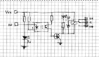
GND is common to 12V VCC and IN, therefore no galvanic isolation between 12V and IN. You would need a separate pin called “IN_GND” (for the optocoupler’s diode return) in order to get full galvanic isolation of the 12V VCC from an MCU connected to IN..
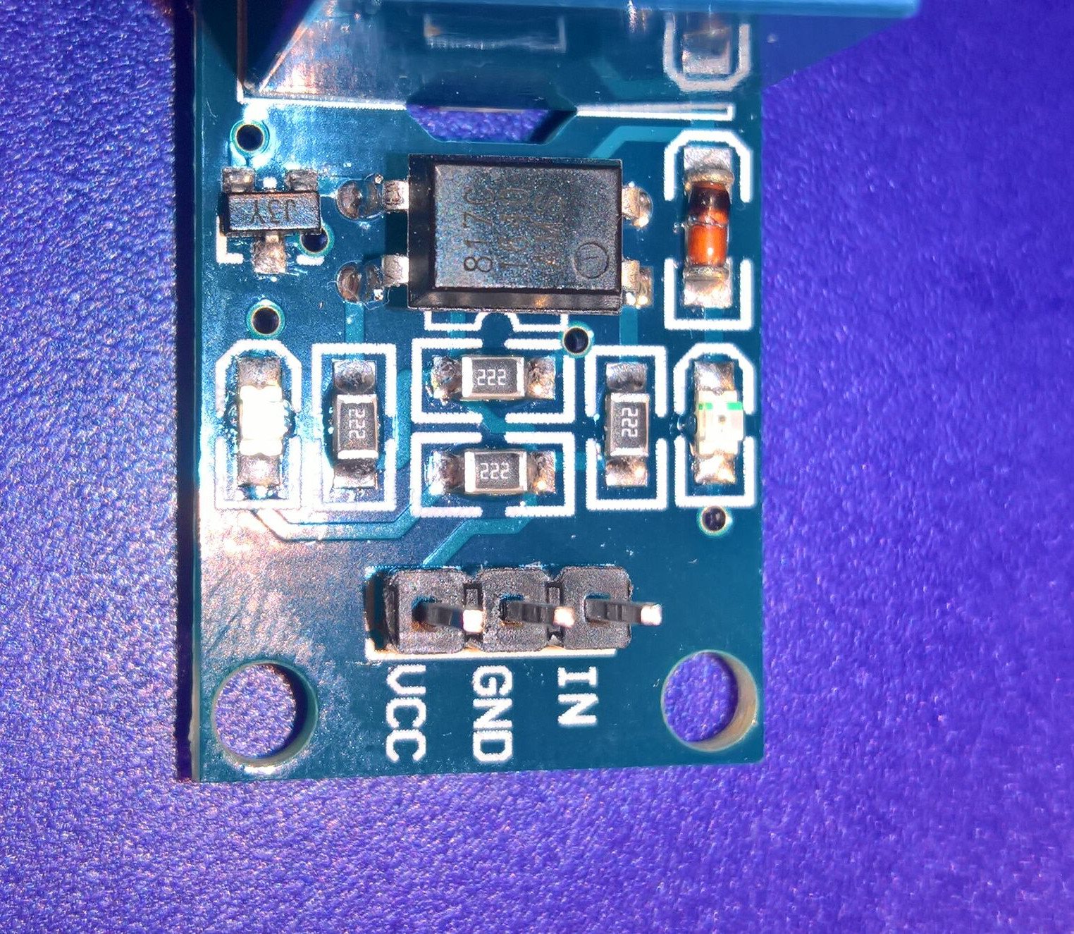
IN is wired straigth into optocouplers kathode and VCC goes through 222 resistor into anode.
The optocoupler there has no specific reason to exist then..
- Ardu relay.JPG (19.91 KiB) Viewed 775 times
Ardu relay.JPG
If VCC is +12V and GPIO pin (IN) from STM is set to LOW then I believe relay is switched. But what happens if IN is set to INPUT or HIGH. VCC is going into optocoupler through resistor so current is small but voltage is still +12V. So there will be current going against pin’s protective diode or ?
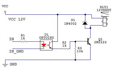
- relay.png (46.23 KiB) Viewed 628 times
might want to recalculate that led resistor as well.
input low => relay energized
pretty sure the relay diode should not be a zener type !
srp
Yeah, this board was for under $1 but does this even work and will it kill my board ? I mean why they sell these…
EDIT: I added 1K5 resistor between IN and GND to lower voltage into ~4.85V, should be safe for GPIO pin…
srp
Wire the 1k5 resistor to 3V3+ on the duino board (+IN below) and the existing -IN(below) header to the PINx at your duino board.
Do not connect GND of your duino board with GND of the 12V source!
Low at the PINx = the current (about 1mA) flows from +3.3V via the 1k5 and via the optodiode into the PINx = relay is activated
High at the PINx = no current flows as the +3.3V and the PINx have the same potential = relay is deactivated
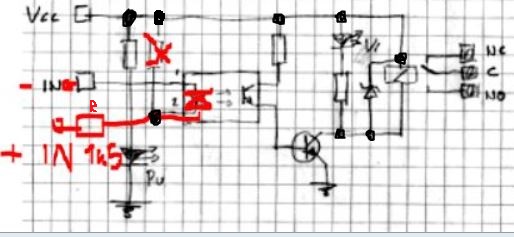
- Really isolated.JPG (46.08 KiB) Viewed 597 times
Pito: any idea why they’re selling this if a) it does not work and b) could brick your board by letting +12V in IN pin ??
Most probably a “designer” got the task to reduce the number of pins on the header from 4 to 3.
So he/she wired the optocoupler’s diode to only voltage available: +12V. Task done !
The dangers of having connected ground and 12V Vcc of that board to a low voltage MCU board are mainly 2:
1. the relay coil, when not protected by the parallel diode (it can break as well), can produce hundreds of volts peaks and destroy the transistor and propagate via 12V rail
2. the relay contacts, which may drive 230V/10A can break and short to the coil and therefore to 12V rail.
PS: another small detail – always ground the base of a transistor (bipolar or fet) which switches loads via a Base-Emitter resistor (see my schema for example) – when left base floating (when connected directly to an MCU’s gpio and the gpio is set input or analog, ie. during reset) or at higher impedance (ie when the optocoupler’s transistor is off) it may randomly switch the collector load off/on/off, based on the noisiness of the environment.

